Note: Descriptions are shown in the official language in which they were submitted.
CA 02428332 2003-05-09
WO 02/38191 PCT/EPO1/13058
METHOD OF INACTIVATING MICROORGANISMS IN A FLUID USING
ULTRAVIOLET RADIATION
Field of the Invention
The present invention relates generally to the sterilization
of fluids such as biological fluids to inactivate undesired
microorganisms such as viruses in the fluids. More specifically,
the invention relates to sterilization of fluids by means of
controlled ultraviolet irradiation.
Background
Sterilization of fluids is an essential step in the
manufacture of many pharmaceutical products and foodstuffs. Tts
goal is the reliable elimination of microorganisms, 'including
viruses, while preserving, as intact as possible, the desirable
components of the products. Sterilization may be required of
biological fluids, such as nutrient media for fermentation,
various blood products, and fluids bearing active pharmaceutical
proteins. In the food industry, sterilization of fluid such as
milk products is common.
CA 02428332 2003-05-09
WO 02/38191 PCT/EPO1/13058
In terms of food sterilization, the selection of a
particular sterilization technique frequently is governed by how
the procedure will affect the shelf life or the palatability of
the food. While the greatest concern in the food industry is
bacterial or fungal contamination, dairy products also may carry
the additional risk of viral or prion contamination. Elimination
or inactivation of such microorganisms is a prerequisite to
commercial distribution of these products.
In contrast to the food industry, the choice and use of a
sterilization technique in the. pharmaceutical industry is subject
to the strict~demands and regulations imposed upon all
pharmaceutical agents that are to be directly administered to an
animal or human. There is particular concern about contamination
of biological fluids such as pharmaceutical products by viruses,
which inay be co-isolated from a natural source or introduced
during a biotechnological process. For the sterilization of
pharmaceutical products, a multi-step process historically has
been employed to inactivate, or remove, or reduce viral
contaminants. Each step in the process is based on different
operational principles to ensure a reduction in the viral load
within a fluid preferably by at least four orders of magnitude
while preserving the viability of proteins and other desirable
components of the fluid.
Irradiation of biological and other fluids with ultraviolet
(W) light has been employed as a method for inactivating
2
CA 02428332 2003-05-09
WO 02/38191 PCT/EPO1/13058
undesirable microorganisms. Irradiating plasma and blood
products, for example, with W-light to inactivate viruses was
known during WW II. W-treatment of blood derivatives is
especially useful for treating uncoated, heat-stable viruses.
Thus, Chin et al., Photochem. & Photobiol. 65, 432 - 435 (1997)
teaches that irradiation of plasma products with UV-light leads
to inactivation of the hepatitis A virus and parvoviruses.
UV-irradiation may inactivate microorganisms and/or viruses
by generating mutagenic alteration of their genetic material.
Above a minimum dose of radiation, the microorganisms lose their
reproductive Capacity. W-irradiation damages riucleic acid by
creating intrastrand nicks anct inaucing nucleotide
photodimerization, both of which disrupt nucleic acid
replication. Through such mechanisms, UV-irradiation can be an
effective means of inactivating undesirable microorganisms within
biological and other fluids. Unfortunately, the energy of short
wavelength UV light also can damage sulfur-containing cysteine
bridges and methionine peptide bonds and induce aromatic amino
acid side reactions, thereby disrupting the structural and
functional integrity of the very proteins that often are the
desired end-products of the irradiated fluid. Thus, an inherent
problem in the application of UV-irradiation techniques is
controlling the irradiation of a fluid so as to ensure sufficient
radiation exposure to, inactivate undesirable microorganisms
within a fluid while at the same time minimizing or eliminating
3
CA 02428332 2003-05-09
WO 02/38191 PCT/EPO1/13058
W-radiation damage to desirable proteins and other components
within the fluid.
Traditionally, W reactors have been used for the W
sterilization of biological fluids. Generally, a W reactor
includes a source of W radiation such as, for example, one or
more elongated tubular bulbs or lamps. In one configuration, an
annular reaction chamber with a predetermined width is formed
around and encloses the lamp and fluid to be irradiated is pumped
or otherwise moved through the chamber, where it is exposed to UV
l0 light from the lamp. In another configuration, a UV source or
sources may surround and radiate 'inwardly into a central tubular
reaction chamber. In either case, flow rate, light intensity,
chamber width or diameter, and reactor length are selected for a
particular fluid to ensure, as much as possible, the most
effective W radiation dosage for deactivating undesirable
microorganisms while conserving the viability of the desirable
components of the fluid.
A problem with the use of W reactors for irradiating fluid
with ultraviolet light results from the finite width of the
reaction chamber and the laminar nature of the fluid flow along
the chamber. More specifically, as the fluid flows along the
chamber, the UV radiation intensity in the treated fluid
decreases relatively rapidly as a function of distance from the
radiation source. This is due to many factors including the
natural inverse=square law of radiation intensity as a function
4
CA 02428332 2003-05-09
WO 02/38191 PCT/EPO1/13058
of distance from a source and the absorption characteristics of
the fluid and the proteinaceous material supporting the
infectious particles. In any event, microorganisms and viruses
within layers of the fluid that flow along the outside of the
reaction chamber farther from the radiation source receive no or
a reduced dosage of radiation. These microorganisms are,
therefore, inactivated slowly or not at all. On the other hand,
microorganisms in layers of fluid that flow along the inside of
the reaction chamber closest to the radiation source receive
increased dosages, and in many cases overdoses, of radiation,
which, in some cases, is high,eiiough to cause significant damage
to desirable proteins and other components in these layers of the
fluid. The result is unpredictable and inefficient sterilization
and higher levels of damage to desirable components.
Attempts to address these limitations have led to the
development of thin-layer or thin film W reactors in which the
width of the reaction chamber and thus the thickness of the fluid
layer adjacent the W source is maintained relatively thin to
reduce the detrimental effects of radiation intensity gradients
in the fluid (see e.g. Kallenbach et al., Cur. Stud. Hematol.
Blood Transfus. Basel 56, 70-82, (1989); Habel et al., J.
Immunol. 56, 273-279(1947); Milzer et al., J. Immunol 50, 331-340
(1945). Oppenheimer et al., Am. ,J. Pub. Health. 49, 903-923,
(1959)). The goal is to ensure that all of the fluid is
constrained to a region of relatively smaller radiation intensity
5
CA 02428332 2003-05-09
WO 02/38191 PCT/EPO1/13058
change as it moves along the radiation source. Thus, the
difference in intensity at various layers within the fluid flow
is theoretically controlled.
While thin-film reactors have been somewhat successful on a
smaller scale, they are problematic in that they can only be
scaled up to industrial production throughput with difficulty.
This is because keeping the film thickness small and constant can
only be realized by increasing the diameter of the reactor and
thereby increasing the cross-sectional area of the film to
accommodate the desired higher throughput. On an industrial
scale, this necessary conditi,ori leads to unmanageably large
reactors. One attempt to circumvent this problem is suggested in
US Patent No. 5,133,932 which discloses a cylindrical thin-film
UV-irradiation reactor in which the area of the film exposed to
the UV-light is increased by corrugating the surfaces of the
reaction chamber. However, the realized increase in throughput
with such a device is marginal at best and still insufficient to
accommodate large scale industrial production.
A further limitation of and problem with traditional W-
irradiation reactors is the unfavorable flow profile and dynamic
conditions of fluid films when in laminar flow along the
radiation source. More specifically, in a laminar flow there is
no or very little fluid exchange normal to the flow direction.
Thus, as mentioned above, fluid layers farther from the source
receive a smaller radiation dose than fluid layers close to the
6
CA 02428332 2003-05-09
WO 02/38191 PCT/EPO1/13058
source. Furthermore, the flow velocity profile within a confined
laminar flow is such that the flow velocity is relatively low
adjacent to the walls of the reaction chamber and is
substantially higher intermediate the walls. Thus, fluid closest
to the wall of the reaction chamber adjacent the light source
flows more slowly and is exposed to the UV radiation
substantially longer than fluid between the walls of the reaction
chamber. Accordingly, to produce the minimum radiation dose
necessary for inactivation of microbial contaminants in the most
l0 rapidly flowing fluid layers, the average residence time of the
fluid in the reactor must be iricxeased. This leads, however, to
increased radiation dosage in the slower moving boundary layers
of the fluid flow and consequent increased probability of
undesired damage to desirable components in these layers. Thus,
destruction of desirable components in the boundary layers due to
overexposure is virtually inevitable.
One adverse result of overexposure in some layers of the
fluid is the generation of free radicals, which become entrained
in the flow and which have adverse effects on desirable
components of the fluid. Attempts to minimise damage caused by
free-radical generation as a result of overexposure typically
include the use of free-radical scavengers in the fluid. Earlier
studies have suggested that the use of free-radical scavengers
can reduce indirect damage to proteins (Chin et al., Photochem.
Photobiol. 65, 432 (1997). Chapman et a1. in U.S. Patent No.
7
CA 02428332 2003-05-09
WO 02/38191 PCT/EPO1/13058
5,922,278 discloses a UV-irradiation sterilisation of biological
fluids wherein free radicals are scavenged by a scavenging agent.
Clark et a1. in U.S. Patent No. 5,786,598 discloses high
intensity pulses of short wavelength light to deactivate
microorganisms. Morgalis-Nunno et al., U.S. Patent No.
6,087,141, discloses the use of light in the wavelength range of
340 - 400 nm (UVA) rather than short wavelengths of about 280 nm
or less. Protection of the desired functionality of the fluid is
afforded by adding a free-radical scavenger in the form of
psoralen. Morowitz et al., U.S. Patent No. 5,981,163 teaches the
addition of quenching protective agents during irradiation
deactivation of viruses. While such techniques attempt to deal
with the free-radicals generated in the fluid, none address the
problems, such as overexposure, that result in the formation of
such free-radicals in the first place.
The disruption of the laminar fluid flow through W reactors
has been proposed as a solution to some of,the forgoing problems.
For example, tangential-flow ring-slot reactors have been
proposed as a means to disrupt and induce mixing within the
laminar flow layers of a UV reactor. EP 803472 A1 discloses a
reactor for UV irradiation of a fluid having an annular or ring-_
slot reaction chamber surrounding a UV radiation source. The
fluid inlet into the reaction chamber is orientated so that the
fluid enters tangentially into the chamber in hopes of generating
fluid cross-mixing. U.S. Patent No. 5,433,738 discloses an
8
CA 02428332 2003-05-09
WO 02/38191 PCT/EPO1/13058
irradiation reactor for the irradiation of water that includes a
helical guide with circular cross section in hopes of generating
fluid cross-mixing.
The tangential inflow solution has proven problematic in
that the fluid flow through the reaction chamber rapidly reverts,
due to wall friction and other hydrodynamic factors, to a fully
axial and laminar profile directed along the longitudinal axis of
the chamber. The Dean vortices, which are theoretically
postulated at least for the area of tangential inflow, and which
are intended to promote cross-exchange of the reaction medium
within the reaction chamber, are surprisingly not present
according to visual studies and CFD-investigations (flow
simulation). Tangential entry ring-slot reactors, therefore,
afford only a limited solution to the problems discussed above.
A need therefore exists for a method of sterilizing a fluid
such as a biological fluid with W radiation that ensures
adequate exposure to inactivate undesirable microorganisms, while
simultaneously minimizing or eliminating damage to desirable
components in the fluid.
A further need exists for an improved method of inactivating
microorganisms in a fluid reaction medium with UV radiation that
eliminates the need to use free radical scavenging or quenching
agents.
There is also a need for a method of sterilizing biological
fluids that is effective at deactivating undesirable
9
CA 02428332 2003-05-09
WO 02/38191 PCT/EPO1/13058
microorganisms while preserving the viability of desirable
components without the use of scavengers and that is scalable to
commercially viable production throughput.
It is to the provision of a method that addresses these and
additional needs that the present invention is primarily
directed.
Summary of the Invention
Briefly described, the present invention is a method of
inactivating microorganisms such as viruses suspended in a fluid
by irradiating the fluid with UV light. The method can be
applied to the sterilization ~of biological products and
foodstuffs, including, but not limited to, blood components,
i'
fermentation media from recombinant technology, milk and milk
products, drinking water, fruit juices and other beverages like
soft drinks, chemical and pharmaceutical products, virus
vaccines, genetically produced drugs arid proteins, drugs and
proteins from transgenic animals and plants, and blood plasma and
products from blood plasma. In a best mode of carrying out the
invention, UV exposure is achieved in a generally tubular reactor
wherein the fluid flows through a reaction chamber that surrounds
an elongated tubular UV light source.
In general, the method comprises the steps of establishing a
primary flow of the fluid in a first direction along the
radiating surface of a W light source and superimposing on the
CA 02428332 2003-05-09
WO 02/38191 PCT/EPO1/13058
primary flow a circulating secondary flow of the fluid. The
secondary flow circulates in a direction substantially transverse
to the radiating surface of the W source such that the entire
volume of the fluid circulates repeatedly toward and away from
the UV source as the primary flow carries it along the length of
the source. As a result, all of the fluid receives a constant
average dosage of W radiation and the problems previously
associated with laminar flows in W reactors, namely overexposure
near the radiating surface and underexposure farther from the
radiating surface, are eliminated.
Further,-and in direct contrast to thin-film reactors, the
reaction chamber in a reactor for carrying out the method of the
present invention may be much wider than an effective "kill zone"
immediately adjacent the radiating surface of the W light source
wherein the intensity of the radiation is always above the
inactivation threshold. This is because, as the fluid circulates
toward and away from the source in the circulating secondary
flow, all of the fluid moves successively into and out of the
kill zone adjacent the surface of the source. The average
residence time of the fluid in the kill zone and thus the
radiation dosage received is a function, among other things, of
the thickness of the kill zone in the particular fluid being
treated, the intensity of the UV light source, and the
characteristics of the primary and secondary flows.
Significantly, these parameters can be controlled as needed,
11
CA 02428332 2003-05-09
WO 02/38191 PCT/EPO1/13058
according to the invention, to establish and maintain an average
kill zone residence time for the entire volume of fluid that
corresponds to a predetermined required dosage of W radiation.
Further, since the reaction chamber can be much wider than
in thin-film reactors, reasonably sized high volume reactors that
are scalable to commercial production throughputs are possible.
Finally, since the average radiation dosage received by all of
the fluid is constant, i.e. no portions or layers of the fluid
are overexposed and none are underexposed, the formation of free-
l0 radicals common in prior art UV reactors is virtually eliminated.
Thus, the method of the invention can be used to sterilize
biological or other fluids without the need to use free-radical
scavengers.
The methodology of the invention, including the
establishment and maintenance of a circulating secondary flow
superimposed on a primary flow, can be realized through a variety
of reactor and reaction chamber configurations. Several such
configurations are discussed in some depth in the detailed
description set forth. It will be understood, however, that the
method of the invention might well be carried out by other
reactor designs and configurations, but that the essence of the
methodology of the invention is substantially the same.
Regardless of the design of the apparatus for establishing and
maintaining the conditions of the invention, the method has been
demonstrated to provide controllable and predictable inactivation
12
CA 02428332 2003-05-09
WO 02/38191 PCT/EPO1/13058
with minimum damage to desirable components, without the need for
free-radical scavengers, and with the potential for commercially
viable throughput. Additional objects, features, and advantages
of the invention will become more apparent upon review of the
detailed description set forth. below when taken in conjunction
with the accompanying drawing figures, which are briefly
described as follows.
Brief Description of the Drawings
Fig. 1 is a simplified schematic representation of a typical
ring-slot~W reactor illustra.ti.ng the characteristics of a
laminar fluid flow.
Fig. 2 a simplified cross-sectional view of a portion of a
UV reactor illustrating fundamental principles of the present
invention.
Fags. 3 through 7 are sectional views illustrating one
embodiment of a UV reactor with rotating agitator usable for
carrying out the methodology of the present invention.
Figs. 8 and 9 are sectional views illustrating an alternate
embodiment of a W reactor usable for carrying out the
methodology of the present invention.
Fags. 10 and 11 are sectional views illustrating another
alternate embodiment of a UV reactor usable for carrying out the
methodology of the present invention.
13
CA 02428332 2003-05-09
WO 02/38191 PCT/EPO1/13058
Figs. 12 and 13 are sectional views illustrating still
another alternate embodiment of a W reactor usable for carrying
out the methodology of the present invention.
Figs. 14 and 15 are sectional views illustrating still
another alternate embodiment of a W reactor usable for carrying
out the methodology of the present invention.
Figs. 16 and 17 are sectional views illustrating yet another
alternate embodiment of a W reactor usable for carrying out the
methodology of the present invention.
l0 Fig. 18 presents two graphs showing ~IlPI potency and porcine
parvovirus (PPV) reduction as,'~ka function of fluency at various
~llPl concentrations and illustrates the determination of critical
parameters in accessing W sterilization methodologies.
Fig. 19 is a graph showing PPV reduction in a solution of 5
mg/ml of t~/1PI proteinase inhibitor as a function of time and
illustrates the results of a WC inactivation of IVIG experiment
applying the methodology of the present invention.
Fig. 20 is a graph of PPV reduction in a solution of 5 mg/ml
of t~/1PI proteinase inhibitor and percent b'1PI activity as a
function of fluency and illustrates the results of another WC
inactivation experiment applying the methodology of the present
invention.
Fig. 21 is a graph of PPV reduction in a solution of 5 mg/ml
of 'dlPI proteinase inhibitor and percent ~IlPI activity as a
14
CA 02428332 2003-05-09
WO 02/38191 PCT/EPO1/13058
function of fluency and illustrates the results of yet another
WC inactivation experiment applying the methodology of the
present invention.
Detailed Description of the Preferred Embodiments
Referring now in more detail to the drawings, wherein like
numerals refer where appropriate to like parts throughout the
several views, Fig. 1 illustrates general principles of fluid
l0 flow through a traditional prior art tubular or ring-slot W
reactor and the problems and shortcomings associated therewith.
The reactor 11, which is shown.in simplified schematic form for
clarity, includes an ultraviolet radiation source in the form of
a centrally disposed elongated tubular W lamp 12. The UV lamp
12 is surrounded by a cylindrical housing 13 having an outer wall
14 and an inner wall 16, which bound and define an annular or
ring shaped reaction chamber 17 surrounding the lamp 12. The
inner wall 16 of the housing is transparent to ultraviolet
radiation such that W light from the lamp 12 radiates into the
reaction chamber 17. The reaction chamber 17 has a predetermined
width defined by the distance between its outer and inner walls
14 and 16 respectively. A fluid inlet port 18 communicates with
the reaction chamber 17 at one end, the bottom end in Fig. 1, and
a fluid outlet port communicates with the reaction chamber 17 at
the opposite end, the top end in Fig. 1.
Fluid to be sterilized is pumped or otherwise fed to the
CA 02428332 2003-05-09
WO 02/38191 PCT/EPO1/13058
fluid inlet port 18 and flows upwardly through the reaction
chamber 17 and along the length of the W lamp as indicated by
arrows 21 before exiting the reaction chamber through fluid
outlet port 19. As the fluid moves through the reaction chamber,
it is exposed to W radiation from the W lamp 12, which acts to
sterilize the fluid by inactivating undesirable components in the
fluid. In the case of the inactivation of viruses within a
biological fluids such as blood products, for example, the W
radiation theoretically inactivates or "kills" the virus
particles within the fluid as the fluid flows through the
reaction chamber.
The enlarged inset in Fig.~l depicts in more detail the
fluid flow pattern through the reaction chamber 17 and its
relationship to the W radiation intensity profile in the chamber
and also illustrates a fundamental cause of problems with prior
art reactors and UV inactivation techniques. More specifically,
the fluid moves through the reaction chamber and along the length
of the UV lamp 12 in a substantially laminar flow, meaning that
there is little if any fluid movement in a direction transverse
to the lamp. In other words, fluid layers within the reaction
chamber tend to retain their relative distances from the W lamp
as the fluid moves along the entire length of the chamber. Thus,
fluid layers near the outer wall 14 tend to stay near the outer
wall and fluid layers near the inner wall 16 tend to stay near
the inner wall. Furthermore, as is true of confined laminar
16
CA 02428332 2003-05-09
WO 02/38191 PCT/EPO1/13058
flows in general, the boundary layers of fluid near the inner and
outer walls of the chamber move more slowly than fluid layers
intermediate the walls, as illustrated by the velocity profile
arrows 21 in Fig. 1. Thus, the residence time in the reaction
chamber of fluid in the boundary layers is greater than the
residence time of fluid in intermediate layers of the flow.
Curve 22 represents the radiation or light intensity within
the reaction chamber 17 as a function of distance from the W
lamp 12. The initial intensity immediately adjacent the W lamp
l0 is relatively high and essentially is the inherent surface
intensity of the lamp itself.' However, as discussed in some
detail above, the light intensity falls off rapidly as a function
of distance from the lamp due to a variety of factors including
the natural inverse square law of radiation intensity and the
light absorption characteristics of the fluid. At some threshold
distance from the lamp, indicated at 23 in Fig. l, the light
intensity is equal to a "critical" intensity, below which UV
radiation levels are insufficient to inactivate viruses within
the fluid. This critical distance defines the outer boundary of
a "kill zone" 24 within which viral inactivation occurs and
outside of which viruses within the fluid are substantially
unaffected by the UV radiation. It will thus be seen that with a
traditional laminar fluid flow through the reaction chamber 17,
layers of fluid within the kill zone are sterilized while layers
of fluid outside the kill zone pass through the reactor without
17
CA 02428332 2003-05-09
WO 02/38191 PCT/EPO1/13058
being sterilized. As a result, reduction of viral load in such a
reactor is subject to natural limits imposed by the fact that
only a portion of the fluid is affected by the W radiation.
In an attempt to address this problem, thin-film reactors
have been developed wherein the width of the reaction chamber
itself is equal to or less than the width of the kill zone. The
theory is that with such a reactor, all of the fluid necessarily
will reside in the kill zone as it moves through the reactor and
thus will be subjected to sufficient doses of radiation to affect
sterilization. However, as mentioned above, such thin-film
reactors cannot be scaled up to, accommodate commercially viable
fluid throughputs with a reasonably sized reactor. Furthermore,
even if practical upscaling were possible, a problem still exists
with thin-film reactors because of the fundamental laminar
character of fluid flow and the nature of the flow velocity
profile across the width of the reaction chamber. More
specifically, even in a thin-film reactor, layers of fluid
adjacent the W source are exposed to substantially higher doses
of radiation than layers of fluid at the outer boundary of the
reaction chamber. Furthermore, because of the flow velocity
profile of a confined laminar flow, layers of fluid adjacent the
W source also experience a longer residence time within the
reaction chamber than layers of fluid intermediate the walls of
the chamber. As a consequence of these conditions, fluid layers
adjacent the UV source tend to be overexposed, which results in a
18
CA 02428332 2003-05-09
WO 02/38191 PCT/EPO1/13058
relatively high instance of damage to desirable components such
as proteins. The overexposure increases the likelihood of the
presence of free radicals within the fluid, which themselves can
result in further destruction of desirable components of the
fluid. Although the use of free radical scavengers is commonly
taught as a solution to this later problem, this represents only
an after-the-fact patch rather than a solution and decreases the
efficiency of the sterilization process.
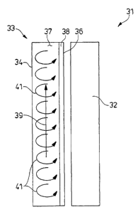
With the forgoing background in mind, Fig. 2 illustrates, in
simplified schematic form, the,,unique methodology of the present
invention for-addressing and el''iminating the problems that plague
prior art W reactors, including thin-film reactors. The
invention is illustrated in Fig. 2 within the context of a
simplified UV reactor 31 having an axially extending W lamp 32
adapted to radiate ultraviolet radiation. in a predetermined
frequency band. In the preferred embodiment, the lamp 32
radiates WC radiation; that is, radiation having a wavelength
between about 180 and 320 nm, or more preferably between about
225 and 290 nm, and most preferably about 254 nm. UVC radiation
is preferred because it tends to cause less detrimental effects
on desirable components such as proteins within a fluid being
treated while retaining sufficient energy to inactivate viruses
and other target microorganisms within the fluid. However, other
types of UV radiation such as, for example, UVA and UvB are
contemplated and are within the scope of the invention.
19
CA 02428332 2003-05-09
WO 02/38191 PCT/EPO1/13058
The UV lamp 32 is disposed along the central axis of a
generally tubular housing 33 having an outer wall 34 and an inner
wall 36 that bound and define an elongated annular reaction
chamber 37. Obviously, the inner wall 36 of the housing is
transparent to W radiation so that UV light from the lamp 32
radiates into the chamber 37. A fluid, such as a biological
fluid, to be treated is pumped or otherwise moved through the
annular reaction chamber 37 by an appropriate pump (not shown) so
that the fluid progresses (in the embodiment of Fig. 1) from the
bottom of the reaction chamber toward the top of the reaction
chamber, where it exits the chamber through an outlet port (not
i
shown). Generally speaking,laslthe fluid moves through the
reaction chamber 37 and along the length of the W lamp 32, it is
irradiated with W radiation from the W source to inactivate
microorganisms such as viruses contained within the fluid.
As discussed above, an inactivation or kill zone 38 is
defined along the inner wall 36 of the reaction chamber. The
width of the kill zone is determined by many factors including
the intensity of the lamp, the composition and optical
characteristics of the fluid, and others; but generally
represents the zone within which the intensity of W radiation is
above a threshold required to affect inactivation of
microorganisms within the fluid. Outside the kill zone 38, the
radiation intensity generally is to low to affect inactivation
and this is the phenomenon that in the past has led to the
CA 02428332 2003-05-09
WO 02/38191 PCT/EPO1/13058
development of thin-film reactors as discussed above.
In the method of the present invention the fluid to be
treated is moved in a primary flow 39 along the length of the
reaction chamber 37 and thus along the surface of the UV lamp 32
as expected. However, and unlike prior art methods, a
circulating secondary flow 41 is established within the fluid and
is superimposed on the primary flow 39. The circulating
secondary flow 41 preferably is generally radially or
transversely relative to the surface of the UV lamp. Thus, as the
fluid moves along the W lamp in the general direction of the
primary flow 3~9, it also circulates repeatedly from the outer
i
wall 34 toward the inner wall 36~of the reaction chamber and back
again in the circulating secondary flow 41. As a consequence,
the fluid moves repeatedly from a region in the reaction chamber
outside the kill zone 38, into and through the kill zone 38 to
the inner wall 36 of the reaction chamber, and thence away from
the inner wall, back through the kill zone, and back into the
region outside the kill zone.
Imagine for a moment a droplet or particle of fluid
entrained within the fluid flowing through the reaction chamber.
The'droplet may contain undesirable microorganisms such as
viruses as well as desirable components such as proteins. As the
droplet moves generally along the length of the reaction chamber
in the direction of the primary flow 39, it also circulates
repeatedly with the superimposed secondary flow first across the
21
CA 02428332 2003-05-09
WO 02/38191 PCT/EPO1/13058
border of the kill zone where it receives the threshold radiation
intensity, then through the kill zone 38 where it receives
progressively increasing radiation intensity until it reaches the
inner wall 37 of the reaction chamber, where it receives the
maximum radiation intensity. From the inner wall, the imaginary
droplet continues to move with the secondary flow away from the
inner wall 36 and back through the kill zone 38, receiving
progressively less radiation intensity, until it moves out of the
kill zone and into the inactive region of the reaction chamber
outside the kill zone.
From.the~forgoing, it wi7.l be appreciated by skilled
~I
artisans that, in each cycle through the kill zone, the imaginary
droplet of fluid experiences an average intensity or dosage of UV
radiation that is greater than the threshold intensity at the
boundary of the kill zone 38 and less than the maximum intensity
at the inner wall 36 of the kill zone. The total radiation
"seen" by the droplet during its residence in the reaction
chamber is therefore approximately equal to the average radiation
experienced in each cycle times the number of repetitive cycles
within the circulating secondary flow 41. The beneficial result
is that each droplet of the fluid, or, in other words, the entire
volume of fluid, experiences a constant average dosage of W
radiation as it moves through the reaction chamber. Further, the
dosage itself can be controlled relatively easily by controlling
the intensity of the W lamp 32, which effects the width of the
22
CA 02428332 2003-05-09
WO 02/38191 PCT/EPO1/13058
kill zone, and the characteristics of the primary flow 39 and the
superimposed circulating secondary flow 41. Therefore, not only
is the entire fluid exposed to a constant average dosage of
radiation, but the dosage is controllable and may be adjusted to
achieve optimum inactivation of undesirable microorganisms while
preserving as intact as possible the desirable components within
the fluid.
The methodology of the invention as illustrated in Fig. 2
contrasts starkly with the processes within prior art laminar
lo. flow UV reactors where, as mentioned above, fluid layers adjacent
the inner wall of the reaction'-chamber tend to be over-irradiated
resulting in unwanted damage to desirable components and the
creation of free radicals, while layers farthest from the inner
wall tend to be under-irradiated resulting in low microorganism
inactivation rates. Thus, it has been found that, with the
method of the present invention, high inactivation rates, on the
order of four orders of magnitude or more in viral inactivation
of biological fluids, can be obtained and consistently
maintained. Further, this level of inactivation is achieved
without the need to introduce free radical scavengers into the
fluid. This is because fewer free radicals are created when
practicing the method of the invention since no portion of the
fluid is over-irradiated as is the case in prior art W reactors.
Finally, and significantly, since the circulating secondary flow
of the present methodology repeatedly moves into and out of the
23
CA 02428332 2003-05-09
WO 02/38191 PCT/EPO1/13058
kill zone regardless of the total width of the reaction chamber,
the constraints that previously gave rise to the development of
thin-film reactors simply are not present. Thus, the reaction
chamber in a reactor for carrying out the invention may be
significantly wider than the thickness of the kill zone itself,
making such a reactor easily scalable to commercial production
throughput while maintaining a reactor of reasonable size. It
will thus be seen that the present invention offers many
significant advantages over prior art UV inactivation methods and
devices.
The methodology of the present invention will now be
described within the context of several exemplary reactor
configurations usable for carrying out the invention as it has
generally been described above. It will be appreciated, however,
that the invention is not limited to or constrained by the
illustrated reactor configurations, but that such are offered to
facilitate a better understanding of the invention and to provide
an enabling disclosure for its practice. In this regard, the
disclosure of German patent application serial no. is
hereby incorporated by reference as if fully set forth herein.
Figs. 3 through 5 illustrate a rotating agitator reactor
usable for carrying out the method of the invention. The reactor
includes an axially disposed elongated W lamp 46 disposed within
a glass mantle or inner housing 47. A tubular housing 48
surrounds the glass mantle 47 and a reaction chamber 49 through
24
CA 02428332 2003-05-09
WO 02/38191 PCT/EPO1/13058
which fluid may flow is defined between the inner wall of the
tubular housing and the glass mantle. The housing is capped arid
sealed at its top end by a head cover 64 and associated O-rings
62 and at its bottom end with a base cover 52 and associated O-
rings 62. An inlet port 59 communicates with the bottom portion
of the reaction chamber 49 for introduction of fluid into the
reaction chamber and an outlet port 61 communicates with the top
portion of the reaction chamber for egress of fluid therefrom.
A rotatable anchor agitator 51 is disposed within the
reaction chamber surrounding the glass mantle 47 and is formed
with from about 4 to about 10,'and preferably about 8, vanes that
surround the glass mantle 47. The anchor agitator 51 is
rotatably journaled at its top end in a sleeve bearing 65 and is
rotatable supported and centered at its bottom end on an agitator
shaft 54 that terminates in a tapered centering tip 53. The
centering tip 53 sits and rides in an appropriately shaped
depression in the bottom of the base cover 52 so that the anchor
agitator is rotatable about the glass mantle 47 in such a way
that its vanes repeatedly circle the glass mantle within the
reaction chamber 49.
A diametrically extending magnetic coupler arm 57 is
attached to the agitator shaft and is adapted to couple
magnetically with the magnetic coupler of a magnetic drive 58.
It will be appreciated that activation of the magnetic drive 58
causes the anchor agitator 51 to rotate within the reaction
CA 02428332 2003-05-09
WO 02/38191 PCT/EPO1/13058
chamber 49. A centering pin 56 depends from the bottom of the
glass mantle 47 and is disposed in a corresponding seat in the
bottom 55 of the anchor agitator 51 to keep the mantle centered
with respect to the anchor agitator and to maintain the
relatively small clearance between the vanes of the agitator and
the surface of the glass mantle. Preferably, but not
necessarily, an array of inwardly projecting flow breakers 63 are
disposed around the inner wall of the housing 48.
Fig. 4 illustrates use of the reactor 44 to carry out the
methodology of the present invention. Fluid to be irradiated is
_,
pumped through the inlet port','S9 and exits out the outlet port 61
!i'
establishing a primary flow 66 along the length of the UV lamp
46. Thus, as the fluid flows upwardly along the length of the
reaction chamber 49, it is exposed to W radiation through the
glass mantle 47. At the same time, the anchor agitator 51 is
rotated to move its vanes around the glass mantle 47. The
movement of the agitator establishes a circulating secondary flow
67 of fluid that has a major component oriented in a direction
transverse to the UV lamp 47. The flow breakers 63 have been
shown to weaken the tendency of the secondary flow to establish
tangential components in favor of a more transverse or radial
flow direction. Thus, the fluid moves repeatedly toward and away
from the UV source in the circulating secondary flows 67 as it
progresses along the length of the reaction chamber with the
primary flow to realize the benefits of the invention as
26
CA 02428332 2003-05-09
WO 02/38191 PCT/EPO1/13058
discussed above. Agitator rotation rate, lamp intensity, and
flow rate are all adjustable to obtain optimum irradiation for a
given fluid being treated in the reactor.
Figs. 6 and 7 illustrate an alternative drive mechanism for
the anchor agitator of Figs. 3 through 5. The sealless drive
mechanism 71 includes a drive housing 70 defining an internal
cylindrical impeller chamber 75 and an outer annular channel 78.
An array of tangentially oriented slots 77 communicate between
the outer channel 78 and the impeller chamber 75. An inlet port
73 communicates with the outer channel 78 and is oriented to
direct fluid tangentially into the outer channel as shown. With
this configuration, fluid moves'around the outer channel and
enters the impeller chamber in a generally tangential direction
as indicated by the arrows in Fig. 7.
The stirrer shaft 54 of the anchor agitator 51 rests on its
tapered end in a corresponding depression in the bottom of the
drive housing 70 such that the anchor agitator is rotatable
within the reactor as described above.' An array of arcuate vanes
72 project outwardly from the stirrer shaft 54 into the impeller
chamber 75 and together form an impeller.
As fluid to be treated moves tangentially into the outer
channel 78 and tangentially into the impeller chamber 75 through
slots 77, the fluid impinges the vanes 72, which imparts rotary
motion to the shaft 54, thus causing the anchor agitator 51 to
2S rotate. Since the motion of the fluid itself causes the rotation
27
CA 02428332 2003-05-09
WO 02/38191 PCT/EPO1/13058
of the anchor agitator, no ancillary drive mechanism, such as the
magnetic drive of Fig. 3, is required. As the fluid moves out of
the impeller chamber and into and through the reaction chamber of
the reactor, the rotating anchor agitator causes circulating
secondary flows superimposed on the primary flow as described
above relative to Figs. 3 and 4.
Figs. 8 and 9 illustrate an alternate embodiment of a UV
reactor usable to carry out the methodology of the present
invention. An elongated W lamp 81 is surrounded by a UV
transparent (preferably quartz) spiral wound flow tube 82
defining a plurality of individual windings 86. The spiral wound
tube 82 terminates at its bottom end in an inlet port 83 that
communicates with the bottom end of the tube 82 and at its top
end in an outlet port 84 that communicates with the top end of
the tube 82. As indicated by the arrows in Fig. 8, fluid to be
treated is pumped into the inlet port 83 and thence moves through
the spiral wound tube 82 around and around the W lamp 81, where
it is exposed to W radiation from the lamp.
As best illustrated in Fig. 9, the windings 86 of the tube
82 are formed with a generally D-shaped cross section having a
generally rectilinear or flat surface adjacent the W lamp and a
curved outer surface. As the fluid flows through the tube in the
general direction of a primary flow 87, the combination of
surface tension, wall friction, and the greater distance that the
fluid must transverse around the outer portion of the tube
28
CA 02428332 2003-05-09
WO 02/38191 PCT/EPO1/13058
results in the formation of circulating secondary flows 88, also
known as Dean vortices, within the tube. The circulating
secondary flows 88 generally are oriented transversely with
respect to and are superimposed on the primary flow, and thus are
oriented generally transversely with respect to the W lamp 81.
Thus, as the fluid moves along the surface of the UV lamp
in the primary flow direction, the circulating secondary flows
carry the fluid toward and away from the W source according to
the methodology of the invention with the many benefits described
l0 above. Obviously, an advantage to the reactor configuration of
Figs. 8 and 9-is that it contains no moving parts or drive
mechanisms. The characteristics of the primary and secondary
flows 87 and 88 respectively, and thus the UV radiation dosage
experienced by the fluid, may be controlled by controlling, where
feasible, the viscosity of the fluid, the dimensions of the
spiral wound tube 82, and the flow rate of the fluid through the
tube.
Figs 10 and 11 illustrate a UV reactor configuration similar
to that of Fig. 8 and 9, but with the spiral wound flow tube of
the reactor having a generally rectangular rather than a D-shaped
cross section. The elongated UV lamp 91 is disposed in and
surrounded by a spiral wound quartz tube 92 defining a plurality
of individual windings 93. An inlet port 94 communicates with
the flow tube 92 at its bottom end and an outlet port 96
communicates with the flow tube 92 at its top end. Fluid to be
29
CA 02428332 2003-05-09
WO 02/38191 PCT/EPO1/13058
treated is pumped into the inlet port and moves through the
spiral wound tube 92 and thus in a spiral pattern along the
surface of the UV lamp in the direction of a primary flow 97
(Fig. 11), and is exposed to W radiation.
As with the embodiment of Figs. 8 and 9, the surface
tension, friction, and path length gradients within the tube 92
combine to create Dean vortices that manifest themselves as
circulating secondary flows 98 superimposed on the primary flow
97. The circulating secondary flows 98 are oriented
substantially transversely relative to the W lamp and thus carry
the~fluid.toward and away from the lamp according to the
methodology of the invention and with the aforementioned benefits
thereof. Again, radiation dosage is controllable by controlling
fluid characteristics, lamp intensity, and flow rate through the
reactor.
Figs. 12 and 13 illustrate still another W reactor
configuration usable to carry out the methodology of the present
invention. The reactor 100 includes an elongated W lamp 101
disposed within a tubular quartz (or other W transparent
material) inner tube 102. An outer housing 103 surrounds the
quartz tube 102 and, in conjunction therewith, defines a reaction
chamber 102 extending along the length of the UV lamp 101. The
housing 103 is capped at its top end by a head cap 106 and at its
bottom end with a base cap 108, each of which is sealed to the
housing 103 and quartz tube 102 with appropriate O-ring seals
CA 02428332 2003-05-09
WO 02/38191 PCT/EPO1/13058
107.
The inner surface of the housing 103 is machined to define a
generally helical channel 109 that spirals continuously around
the quartz tube 102 from the bottom of the reactor to the top.
The helical channel approaches but does not engage the quartz
tube 102 and thus defines a series of relatively narrow passages
111 between each turn of the helical channel and the quartz tube
102. An inlet port 112 communicates with the reaction chamber
104 at the bottom of the reactor and an outlet port 113
communicates with the reaction chamber 104 at the top of the
reactor.
In use to carry out the~methodology of the present
invention, fluid to be treated is pumped into the reactor through
the inlet port and flows generally around the helical channel and
along the surface of the UV lamp in a primary flow 114. This
motion of the primary flow generates circulating secondary flows
116 in the form of Dean vortices as a result of fluid dynamical
interactions within the D-shaped channel. The circulating
secondary flows 116 are superimposed on the primary flow 114 and
carry the fluid toward and away from W source according to the
methodology of the present invention.
At the same time, the spaces 111 permit a small volume of
the fluid to flow longitudinally along the length of the reactor
in a free jet flow 116 (Fig. 13). The fluid in the free jet flow
116 is directed almost perpendicularly onto the spiraling primary
31
CA 02428332 2003-05-09
WO 02/38191 PCT/EPO1/13058
flow 114. The interaction between the two flows causes an
enhancement of the circulating motion of the secondary flows 116
as a result of the fluid dynamical forces generated by the
interacting flows. This, in turn, leads to an improved and more
even irradiation of the fluid as it moves through the reactor.
W irradiation dosage can be adjusted and controlled by
controlling the dimensions of the helical channel, the size of
the spaces 111, the viscosity of the fluid, the intensity of the
lamp 101 and the fluid flow rates through the reactor.
Figs. 14 and 15 illustrate yet another embodiment of a W
reactor usable to carry out the,methodology of the present
invention. The reactor 119 is similar in some respects to the
reactor of Figs. 12 and 13 and includes an elongated W lamp 121
surrounded by a quartz tube 122. An outer housing 123 surrounds
the quartz tube 122 and in conjunction therewith defines a
reaction chamber 124 that extends along the length of the UV lamp
122. The housing is capped at its top end by a head cap 126 arid
its bottom end by a base cap 127, each.of which is sealed to the
housing and the quanta tube with appropriate O-rings 128. An
inlet port 129 communicates with the reaction chamber at the
bottom thereof and an outlet port communicates with the reaction
chamber at its top end.
The inner wall of the housing 123 is machined or otherwise
formed with a series of generally annular channels 132 separated
by inward protrusions 135. The inward protrusions 135 approach
32
CA 02428332 2003-05-09
WO 02/38191 PCT/EPO1/13058
but do not touch the quartz tube, thus defining relatively narrow
passages 134 between the channels 132. An array of generally
ring-shaped baffles 133 project outwardly from the quartz tube
122 with each baffle being disposed within a corresponding one of
the annular channels 132.
In use to carry out the methodology of the present
invention, fluid to be treated is pumped into the inlet port 129
and moves along the reactor 119 to be extracted at the outlet
port 131. As best illustrated in Fig. 15, the fluid moves
generally in a primary flow 136 along the length of the UV lamp
and~through the spaces 134, which confine the flow to a region
close to the W source. However, when the primary flow
encounters a baffle 133, it is diverted toward the outside of the
reaction chamber to a location farther from the W source. On
the other side of the baffle 133, the primary flow is again
diverted back toward the UV source, and then flows through the
next space 134 to the next succeeding channel and baffle
combination,
Thus, it will be seen that the primary flow 136 itself moves
repeatedly toward and away from the W source to obtain benefits
of the present invention. In addition, the movement and
displacement of the primary flow 136 within each chamber creates
circulating secondary flows 137 that are oriented generally
transversely relative the UV lamp and thus carry the fluid toward
and away from the W source according to principles of the
33
CA 02428332 2003-05-09
WO 02/38191 PCT/EPO1/13058
invention. The circulating secondary flows therefore enhance the
cross mixing that characterizes the present invention and results
in the benefits thereof.
Figs. 16 and 17 illustrate still another embodiment of a W
reactor within which the methodology of the present invention may
be carried out. The reactor 140 is similar in many respects to
the reactor 119 of Figs. 14 and 15 and includes an elongated W
lamp 141 disposed within a quartz tube 142. A housing 143
surrounds the quartz tube 142 and in conjunction therewith
defines a reaction chamber 148. The housing is capped at its top
end by a head~cap 144 and at ~asrbottom end by a base cap 146,
each of which is sealed to the housing and the quartz tube by
appropriate O-rings 147. A fluid inlet port 153 communicates
with the bottom of the reaction chamber 148 and an outlet port
154 communicates with the top of the reaction chamber for ingress
and egress respectively of fluid to be treated.
The inner wall of the housing 143 is machined or otherwise
formed with an array of generally annular chambers 149 separated
by respective partitions 151. The partitions extend toward but
do not engage the quartz tube 142 to define relatively narrow
passages 152 between the partitions and the quartz tube. In use,
fluid to be treated is pumped through the inlet port 153 and
moves upwardly along the length of the UV lamp to be extracted
through the outlet port 154. As illustrated in Fig. 17, the
fluid moves in a primary flow 156 through the passageways 152 and
34
CA 02428332 2003-05-09
WO 02/38191 PCT/EPO1/13058
along the length of the UV lamp 142. The motion of the fluid in
the primary flow past successive ones of the annular channels 149
creates vortices that result in circulating secondary flows 157
superimposed on the primary flow within each of the annular
chambers. The circulating secondary flows are oriented
substantially transversely relative to the W lamp so that the
fluid moves with the secondary flows repeatedly toward and away
from the W lamp according to the methodology of the present
invention. The result, again, is even and constant irradiation
of the entire volume of fluid with all the attendant benefits
thereof as discussed in detail.above.
The invention will now be described and further
characterized within the context of various examples that
represent experiments and clinical trials conducted by the
inventors. It will be appreciated that the techniques of and the
data presented in conjunction with the examples are not intended
to be limiting, but are presented for a better understanding and
more complete and enabling disclosure of the methodology of the
invention. Many modifications might well be made to the examples
presented herein and other experiments not discussed below might
be carried out, all within the scope of the present invention.
Example 1
Critical parameters .ice a process to inactivate virus particles by
UV radiation.
CA 02428332 2003-05-09
WO 02/38191 PCT/EPO1/13058
The goal of viral inactivation by UVC irradiation is to
inactivate high levels of virus without damaging the protein or
functionality of interest. Two parameters were found to be
critical to achieving this goal; namely protein concentration in
'S the fluid, and UV fluency. Fluency is dependent on the physical
configuration of the W irradiator, since internal flow patterns
significantly affect the amount of W light that is received by
any given protein molecule or virus panicle in suspension.
Since proteins absorb in the W range, high protein
concentrations can serve to protect the bulk of the target
protein from WC damage. The~high protein concentration,
however, will also protect the virus. It is necessary therefore
to independently evaluate both protein integrity and viral
inactivation at varying protein concentrations, and then to
select a concentration of protein for the inactivation process
that will maximize protection of the integrity of the target
protein as well as viral reduction.
Thus, the WC induced potency loss was determined as a
function of protein concentration, as shown in Fig. 18, chart A.
The WC-induced potency loss was least at concentrations of 12.5
mg/ml a 1 proteinase inhibitor, but increased at protein
concentrations of 7.0, 5.0 and 4.0 mg/ml. The greatest effect on
potency was seen at the lowest protein concentration, 2.5 mg/ml.
In contrast, as shown in Fig. 9B, the smallest reduction in virus
infectivity was observed at the highest a 1 proteinase inhibitor
36
CA 02428332 2003-05-09
WO 02/38191 PCT/EPO1/13058
concentration of 12.5 mg/ml, and the highest level of
inactivation was observed at the lowest concentration, namely 2.5
mg/ml. Based on these data, 5 mg/ml of a 1 proteinase inhibitor
was used for UVC inactivation as a compromise between acceptable
protein potency and good viral inactivation.
Model Virus Studies
TTirus Stocks. Porcine Parvovirus (PPV), strain Tennessee, a
l0 non-enveloped, single-stranded DNA virus was used in these
studies as a model for human parvovirus B19. This virus has been
shown to be resistant to inactivation by several methods,
including pasteurization and dry heat.
Virus stocks were prepared by infection of porcine testicle
(PT) cells. Virus was propagated by infecting subconfluent
monolayers of PT cells at a low multiplicity of infection, adding
propagation medium and then incubating the cells at 37°C in 5%
C02 until advanced cytopathology was observed. Virus propagation
media consisted of minimum essential medium, Earle s salts
supplemented with 7.5% fetal bovine serum and NHG. NHG was added
to prevent contamination and provide for the additional media
requirements of this cell line and consisted of 0.1 mM
nonessential~amino acids, 10 mM HEPES (N-[2-
Hydroxyethyl]piperazine-N -[2-ethanesulfonic acid], 0.05 mg/ml
gentamicin and fungizone (2.5 mg/ml Amphotericin B). Infected
37
CA 02428332 2003-05-09
WO 02/38191 PCT/EPO1/13058
cells were disrupted by freeze-thawing and the cell lysates were
stored at about -70°C until used. The virus spike for each
experiment was prepared by thawing the virus-infected cell
lysate, centrifuging at low speed (4000 x g) to remove the cell
debris and collecting the clarified supernatants.
Virus Assay.
Viral inactivation by UVC was determined by endpoint dilution in
96-well microtiter plates seeded with PT cells and using MEM
,.
containing 7.5o FBS and NHG. ~~Virus was diluted using serial half
log dilutions of the test sample or positive control in Hank s
Balanced Salt Solution (HBSS). Positive controls consisted of
the same lot of virus that was used as the virus spike. Unspiked
HBSS was used as a negative control. Each dilution was used to
inoculate 8 wells of a 96-well microtiter plate. After 7 days
incubation at 37°C in 5o CO~, cytopathology was scored. Results
were converted into a titer (log median tissue culture infective
dose per ml; TCIDSO/ml) by the method of Spearman and Karber
(Cavalli-Sfprza, L. Biometrie Grundzuge biologisch-medizinischer
Statistik [Biometry, the basics of biological and medical
statistics], Gustav Fischer Verlag Stuttgart, 1974, p. 171-173.)
A variety of viral species were tested for their relative
inactivation susceptibilities.
38
CA 02428332 2003-05-09
WO 02/38191 PCT/EPO1/13058
Table 1. Inactivation of virus with varying genome sizes and types of nucleic
acid. D4 is defined as the UV
dose required to reduce or inactivate the virus by 4 log magnitudes.
virus genome genome envelope D4
size type (Joule
s/cm2)
PPV 5 kb DNA no 0.19
SV-40 5 kbp DNA no 0.14
polio 7.7 kb _ no 1.125
RNA
HAV 7.5 kb RNA no 2.25
FIV 10 kb RNA yes
Sindbi 11.3 kb RNA yes 1.125
s
BVDV 12 kb RNA yes 2.25
Reo 23.5 kbp RNA no 2.25
Adeno 36kbp DNA no 9
PRV 150 kbp RNA yes 9
~ As shown in Table 1, the processes of the present invention
i _.
inactivate PPV at a smaller fluency than other viruses, but all
were inactivated by at least four orders of magnitude when
exposed to fluencies within the range .014 - 9.0 Joules/cm2.
Also, the smaller the viral genome, typically the smaller the
effective fluency value.
Example 2
Protein Integrity.
Following WC exposure the retention of immunoglobulin
integrity was assessed by evaluating the extent of aggregation
and fragmentation of the molecule. This was done by size-
exclusion HPLC using a TSK-63000 (Toro-Haas) column and 0.91 M
NazHP04, pH 5.2 - 0.2 M NaCl buffer. Immunoglobulin integrity
39
CA 02428332 2003-05-09
WO 02/38191 PCT/EPO1/13058
was expressed as the area percent monomeric protein.
For alPI, protein integrity was assessed by determining the
ability of the enzyme to inhibit porcine elastase. Protein
integrity was expressed as the percent of the activity before WC
exposure.
Inactivation of PPT7 in IGIV.
Pre-formulation IGIV was diluted to 0.8o with water,
adjusted to pH 4.2 and spiked to 10% with PPV. To evaluate the
effect of UVC -exposure on protein integrity, unspiked IGIV
solutions were used. Solutions of IGIV were pumped through a
tubular W reactor with a peristaltic pump, calibrated to deliver
100 ml/min. The protein solution was pumped through the device
and re-circulated through a stirred reservoir containing the
sample. The protein solution was re-circulated though the entire
assembly for 5, 10, 15, 30 and 60 minutes, corresponding to
fluencies of 2.8, 5.6, 8.4, 16.9 and 33.8 Joules/cm2,
respectively. In this case fluency was defined as the mean
residence time (reactor volume divided by volume flow rate)
multiplied by the W light intensity at the surface of the
reaction chamber nearest the W source (which may be the surface
of a quartz sleeve surrounding the UV lamp). For these
calculations, ideal plug flow was assumed. As shown in Fig. 19,
after 5 minutes of re-circulation, four logs of PPV reduction was
CA 02428332 2003-05-09
WO 02/38191 PCT/EPO1/13058
observed, and by 30 minutes, over seven logs of inactivation was
seen. After 60 minutes of UVC exposure, 95% monomeric IgG
remained.
Example 3
Inactivation of PPV in alphas proteinase inhibitor.
Alphas proteinase inhibitor (~/1PI) was diluted to 5 mg/ml in
20 mM Na phosphate, pH 7.0 and 100 mM NaCl and exposed to UVC in
the same device as used in example 1. During this experiment,
however, the solution was pumped through the device in a single
pass at flow rates between 25!'and 1200 ml/minutes, resulting in
fluencies ranging from 0.19 18 Joules/cm2.
To evaluate virus reduction, the protein solution was spiked
to 10% with PPV and to evaluate protein integrity, unspiked
solutions were exposed to WC. From Fig. 20 it can be seen that
at fluencies above 0.6 Joules/cm~ at least 4 logs of PPV was
inactivated. As is also shown in Table 2 at higher fluencies PPV
was reduced to a level below that of detection; variation in log
reduction was observed due to variation in starting titers of the
spiking virus. At least 95% of ~/1PT activity remained after
exposure to fluencies less or equal to 2.3 Joules/cm2.
41
CA 02428332 2003-05-09
WO 02/38191 PCT/EPO1/13058
Table 2
Fluency Loglo PPV Reduction% Initial aIPI
(J/cm2) activity
18 4.2 76.2
n=I n=1
9 4.8 0.9 87.6 2.1
n=4 n=4
4.5 5.30.4 91.94.5
n=s n=7
2.3 5.4 0.1 96.5 1.2
n=4 n=2
1.5 5.40.1 96.73.4
n=3 n=3
1.1 5.2 0.1 100
n=3 n=I
_ . ,1.0 4.7 -0.4 100.0 0.0
y=2 n=2
0.8 4.60.4 98.9 1.1
n=2 n=2
0.6 3.6 ND
n=I
0.5 2.9 0.4 ND
n=2
0.38 2.6 ND
n=I
0.3 2.6 ND
n=1
0.49 2.1 ND
n=1
42
CA 02428332 2003-05-09
WO 02/38191 PCT/EPO1/13058
Example 4
Tnactivation of PPV in alphas proteinase inhibitor.
Solutions of fllPI that had been diluted to 5 mg/ml in 20 mM
Na phosphate, pH 7.0 100 mM NaCl were exposed to WC in a
second type of tubular reactor, wherein the inlet and outlet
ports are off-set. This produces a flow pattern that is
primarily tangential, but which also contains a radial component
to the annular flow in the reactor ( tangential flow reactor ).
For evaluation of virus reduction, the protein solutions were
spiked to 10o with PPV. The data shown in Fig. 21 indicate that
in this reactor four logs of P'PV inactivation can be inactivated
I
i____
at lower fluencies than in the tubular reactor used in Examples
10 and 11. At least 95% of the initial ~/1PI activity was
observed at fluencies that were less than or equal to 2
Joules/cmz. Since the same W lamp and the same light intensity
was used in all of the experiments, this demonstrates that
improved hydrodynamic conditions (mixing), i.e. inducing a
circulating secondary flow within the primary flow, reduce the
total residence time of protein solution in the reactor that is
necessary to gain adequate virus inactivation.
43
CA 02428332 2003-05-09
WO 02/38191 PCT/EPO1/13058
Example 5
Graph
A
-
Log
PPV
reduction
in
a
solution
of
5
mg/ml
alphas
proteinase
inhibitor
as
function
of
fluency
in
three
different
tubular
reactors.
6
5
c
4
O
0
3
H i
L
_
2
~
Tubular
Reactor
1
/
Tangential
Flow
Reactor
~
S
Iral
Flow
Reactor
0
0
0.1
0.2
0.3
0.4
0.5
0.6
0.7
0.8
0.9
1
Fluency
[J/cm2]
Graph A shows the result of studies evaluating the
inactivation of porcine parvo virus (PPV) in a solution of 5
mg/ml alphas proteinase inhibitor in three different reactor
configurations. It can be seen that a threshold of 4-log virus
reduction can be achieved at an approximate fluency of 0.7 J/cm2
in a simple tubular reactor, similar the prior art reactor shown
44
CA 02428332 2003-05-09
WO 02/38191 PCT/EPO1/13058
in Fig. 1. Improved hydrodynamic conditions, especially an
increase in radial flow components in a reactor with tangential
flow characteristics and a reactor with a spiral wound reaction
chamber (see Fig. 8) lead to a significant decrease in W light
energy that is necessary to sterilize plasma solutions. These
data demonstrate that 4-logs of PPV inactivation can be achieved
at approximately 0.15 J/cm2 in a tubular reactor with tangential
inlet and outlet a. In.a reactor with spiral wound reaction
chamber less than 0.1 J/cm2 are sufficient to inactivate 4-log of
PPV. It should be noted that log reduction values between 4.5 and
5 may approach~the detection limit of the virus assay and the
actual virus reduction may even be higher.
These results are consistent with data generated using a UV
photosensitive substance instead of viruses. In this case, the W
induced formation of triiodide ions from iodide ions was used,
following an approach described by Rahn (Rahn, R.O.;
Photochemistry and Photobiology 58(1993)6, 874-880, ibid
66(1997)4, 450-455). Here, potassium iodide was used as a UV
photosensitive component to determine the W light intensity at
254nm, delivered to the reaction medium in the same three
reactors used in Graph A. Comparison of the measured light
intensity with the light intensity that is emitted by the W bulb
gives a W light yield. Since the penetration depth of W light
into a potassium iodide solution is extremely small (less than
1mm) under the given conditions, it can be approximated that
CA 02428332 2003-05-09
WO 02/38191 PCT/EPO1/13058
iodide conversion only occurs directly at the surface of the
quartz sleeve that encapsulates the W bulb. It is obvious
therefore that hydrodynamic conditions, especially radial mixing
as a result of circulating secondary flow patterns, should
determine the light yield. Data shown in Graph B clearly confirm
this. Due to superior hydrodynamic conditions the highest light
yield can be found in the reactor with a spiral wound reaction
chamber, compared to the other two reactors. Data in Graph B show
that radial mixing, i.e. an increase in the circulating secondary
flow, increases with increasing flowrate. In the reactor with a
spiral wound chamber,
so.o __~-_..
~o.o
60.0
50.0
0
m
?~
40.0
w
s
rn
.1
30.0
20.0
Tubular
Reactor
'~
enllal
Flow
Reactor
Tan
10.0 g
S iral
Flow
Reactor
0.0
0
500
1000
1500
2000
2500
Flow
Rate
jmllmin~
Graph B - UV light yield as a function of flow rate in three different tubular
reactors.
however, the degree of mixing seems to level off at flow rates
higher than 1000 mljmin. Since radial mixing is slightly better
46
CA 02428332 2003-05-09
WO 02/38191 PCT/EPO1/13058
in the reactor with tangential inlet and outlet light yield is
higher compared to a simple tubular reactor.
Example 6
l0 Graph C shows the result of studies assessing the
inactivation of Reo-virus 3 in a solution of 5 mg/ml alphas
proteinase inhibitor in the UV reactor with a spiral wound
reaction chamber. It can be seen from this that Reo inactivation
increases with increasing fluency and reaches a 4-log reduction
at approximately 0.15 J/cm2. At the same time protein activity is
not impacted, but it declines at fluencies above 0.15 J/cma. The
fluency value of 0.15 J/cm~ corresponds to a flow rate of
1000m1/min. As noted in Fig. YYY mixing apparently approaches a
limit at flow rates above 1000 ml/min in this device and
plateaus. Further increase of flow rate (decreasing of fluency)
thus decreases the overall residence time of the virus in the
kill zone in the reactor and therefore leads to a reduced virus
inactivation. At the same time protein activity declines with
reduced flow rates (increasing fluency). This example suggests
that there is an optimum flow rate where hydrodynamic conditions
are appropriate to assure proper mixing, but at the same time
overall residence time is still high enough to effectively kill
virus and leave sufficient high protein activity. This flow rate
47
CA 02428332 2003-05-09
WO 02/38191 PCT/EPO1/13058
depends not only on reactor design and configuration, as
demonstrated, but also on the virus and protein properties and
their respective concentrations, as described earlier. Therefore,
optimal flow rates need to be determined experimentally for each
given system.
5 - --w- 100
4.5
98
4
3.5
c 96
0 0
r
3
v
2.5 94
Q
N
L
_
2
o
a
g2
1.5
1
90
0.5
0 88
0.07 0.09 0.15 0.3 0.7
Fluency [J/cm~]
Graph C - Log reduction of Reo-virus and remaining protein activity of alphas
proteinase inhibitor (5 mg/ml)
in the reactor with spiral wound reaction chamber
The invention has been described herein in terms of
preferred embodiments, configurations, methodologies, and
examples. It will be understood by those of skill in the art,
however, that a variety of additions, deletions, and
48
CA 02428332 2003-05-09
WO 02/38191 PCT/EPO1/13058
modifications might well be made to the illustrative embodiments
without departing from the spirit and scope of the invention as
set forth in the claims.
49