Language selection

Search

Patent 2428672 Summary

Third-party information liability

Some of the information on this Web page has been provided by external sources. The Government of Canada is not responsible for the accuracy, reliability or currency of the information supplied by external sources. Users wishing to rely upon this information should consult directly with the source of the information. Content provided by external sources is not subject to official languages, privacy and accessibility requirements.

Claims and Abstract availability

Any discrepancies in the text and image of the Claims and Abstract are due to differing posting times. Text of the Claims and Abstract are posted:

  • At the time the application is open to public inspection;
  • At the time of issue of the patent (grant).
(12) Patent Application: (11) CA 2428672
(54) English Title: BULLET ENDED WASH TUBE FOR DISHWASHER
(54) French Title: TUBE DE LAVAGE A EXTREMITE CONIQUE POUR LAVE-VAISSELLE
Status: Deemed Abandoned and Beyond the Period of Reinstatement - Pending Response to Notice of Disregarded Communication
Bibliographic Data
(51) International Patent Classification (IPC):
  • A47L 15/42 (2006.01)
  • A47L 15/22 (2006.01)
  • A47L 15/50 (2006.01)
(72) Inventors :
  • ELICK, ROBERT A. (United States of America)
  • MORRISON, JOHN TREVOR (United States of America)
(73) Owners :
  • MAYTAG CORPORATION
(71) Applicants :
  • MAYTAG CORPORATION (United States of America)
(74) Agent: FINLAYSON & SINGLEHURST
(74) Associate agent:
(45) Issued:
(22) Filed Date: 2003-05-13
(41) Open to Public Inspection: 2003-12-27
Examination requested: 2008-02-08
Availability of licence: N/A
Dedicated to the Public: N/A
(25) Language of filing: English

Patent Cooperation Treaty (PCT): No

(30) Application Priority Data:
Application No. Country/Territory Date
10/184,405 (United States of America) 2002-06-27

Abstracts

English Abstract


an improved wash tube is provided for a dishwasher. The wash tube is
mounted on the upper rack and has a first end adapted to be releasably docked
with the water manifold in the back of the dishwashing chamber as the rack is
moved between the extended loading position and the retracted wash position.
The inner end of the wash tube includes a curved cap which increases the
docking
tolerance and which presents a substantially downwardly oriented water inlet
to
the wash tube. The cap creates water stagnation adjacent the inlet such that
the
water velocity is substantially reduced and the pressure increased. The second
end
of the wash tube is connected to the spray arm which rotates as water is
ejected
from the spray arm nozzles at increased pressure. The cap allows the wash tube
to
fully dock into the manifold without obstructing the water inlet.


Claims

Note: Claims are shown in the official language in which they were submitted.

The embodiments of the invention in which an exclusive property or
privilege is claimed are defined as follows:
1. A wash tube for a dishwasher having a wash chamber, a rack movable
between an extended loading position substantially out of the washer chamber
and
a retracted washing position within the wash chamber, a water manifold in a
rear
wall of the wash chamber, and a spray arm for spraying water onto objects to
be
cleaned. the wash tube comprising:
an elongated body having a first end adapted to releasably dock with the
manifold
and a second end adapted to be mounted to the spray arm; and
the first end having a cap to direct water from the manifold to the body.
2. The wash tube of claim 1 wherein the cap is tapered to facilitate docking,
of
the wash tube into the manifold.
3. The wash tube of claim 1 wherein the cap defines a downwardly facing
inlet opening for directing water into the body.
4. The wash tube of claim 1 wherein the cap has rearward edge to limit the
extent of docking of the wash tube into the manifold.
5. The wash tube of claim 1 wherein the cap has a curved upper surface to
reduce the velocity of water flow at the first end of the body and to increase
the
pressure of water in the body.
6. The wash tube of claim 1 wherein the cap extends substantially through
the manifold.
7. The wash tube of claim 1 wherein the body includes a flexible portion to
facilitate docking.
5

8. The wash tube of claim 1 wherein the body includes bellows for flexibility.
9. The wash tube of claim 1 wherein the body is curved along its length.
10. The wash tube of claim 1 wherein the second end of the tube includes a
downwardly directed outlet opening for directing water into the wash arm.
11. A wash tube for a dishwasher having a wash chamber, a rack movable
between an extended loading position substantially out of the washer chamber
and
a retracted washing position within the wash chamber, a water manifold in a
rear
wall of the wash chamber, and a spray arm for spraying water onto objects to
be
cleaned, the wash tube comprising:
an elongated body having a first end adapted to releasably dock with the
manifold
and a second end adapted to be mounted to the spray arm; and
the first end having a downwardly directed inlet opening fur receiving water
from
the manifold.
12. The wash tube of claim 11 wherein the first end is adapted to engage a
back inner surface of the manifold without restricting water flow into the
inlet
opening of the first end.
13. The wash tube of claim 11 wherein the first end extends over the opening
to direct water from the manifold into the inlet opening.
14. The wash tube of claim 11 wherein the first end reduces water velocity and
increases water pressure in the body.
15. The wash tube of claim 11 wherein the body includes a flexible portion to
facilitate docking.
6

16. The wash tube of claim 11 wherein the body includes bellows for
flexibility.
17. The wash tube of claim 11 wherein the second end of the tube includes a
downwardly directed outlet opening for directing water into the wash arm.
18. A wash tube for a dishwasher having a wash chamber, a rack movable
between an extended loading position substantially out of the washer chamber
and
a retracted washing position within the wash chamber, a water manifold in a
rear
wall of the wash chamber, and a spray arm for spraying water onto objects to
be
cleaned, the wash tube comprising:
an elongated body having a first end adapted to releasably dock with the
manifold
and a second end adapted to be mounted to the spray arm; and
the first end being adapted to engage a back inner wall of the manifold
without
restricting water flow from the manifold into the tube.
19. The wash tube of claim 18 wherein the first end has a downwardly directed
inlet opening for receiving water from the manifold.
20. The wash tube of claim 18 wherein the first end reduces water velocity and
increases water pressure in the body.
21. The wash tube of claim 18 wherein the body includes a flexible portion to
facilitate clocking.
22. The wash tube of claim 18 wherein the body includes bellows for
flexibility.
23. The wash tube of claim 18 wherein the second end of the tube includes a
downwardly directed outlet opening for directing water into the wash arm.
7

Description

Note: Descriptions are shown in the official language in which they were submitted.


CA 02428672 2003-05-13
BULLET ENDED WASH TUBE FOR DISHWASHER
BACKGROUND OF T'HE INVENTION
Dishwashers typically have upper and lower racks for holding objects to be
washed. Rutatable spray anus a~°e provided in the chamber for spraying
water
unto the objects for cleaning. Often times, one of the spray anus is
positioned
between the upper and lower racks, with a wash tube extending between the
spray
anmu~d the water manifold in the back wall of the washing chamber. The wash
tuba is connected to the upper rack and is adapted to dock to and undock from
the
water manifold, such that the wash tube and spray aan move with the rack
between the extended leading position substantially outside of the wash
chamber
and the r~etractc;d wash position within the wash chamber.
'fhe clucking of the wash tube with the water manitold presents several
problems in the prior art. First, the wash tube must be aligned with the
manifold
opening to allow for proper docking. While a tapered end en the wash tube has
somewhat reduced the docking alignment problem, the flat or planer end of the
wash tube still creates alignment problems.
Secondly, the tlat end of the wash tube defines an opening or inlet which is
in a plane parallel to the water flow in the water manifold. Thus, the t7ow of
water
from the manifold into the wash tube is not efficient. Also, the water in the
wash
2 o tube is nut at optimal pressure.
Accordingly, a prit~~ary objective of the present invention is the provision
of an improved wash tube for a dishwasher which overcomes the problems of tire
prior art.
Another objective of the present invention is the provision of a bullet
2 5 ended wash tLibe to provide improved coupling of the wash tube with the
water
manifold in the rear ofthe dishwasher.
A further objective of the present invention is the provision of a wash tube
having a first end which couples with the manifold, wherein the tirst end
includes
a cup fur directing water from the manifold into the wash tube.
1

CA 02428672 2003-05-13
Still another objective of the present invention is the provision of a wash
tube having a first end with a downwardly oriented inlet.
Another objective of the present invention is the provision of an improved
dishwasher wash tube which increases the water pl°essure from the water
manifold
to the spray artn.
Still another objective of the present, invention is the provision of an
improved dishwasher wash tube which bottoms out on the rear inner surface of
the
water manifold without restricting the flow of water into the wash tube.
~~hese and other objectives will be apparent ti-om the following description
of the invention.
SUM1MARY OF THE INVENTION
An improved wash tube is provided for a dishwasher having a wash
chamber and a rack mruvable between an extended loading position substantially
out cof the wash chamber and a retracted cleaning position within the wash
chamber. The dishwasher has a water manifold in a rear w -all of the wash
clnanober. The wash tube is mounted to the rack, and extends between the water
manifold and a rotatable spray arts for spraying water onto objects to be
cleaned.
The tube has an elongated body with a first end adapted to re;leasably dock
with
the water manitold, and a second end adapted to be mounted to the spray ann.
2 o The tirst end has a bullet-shape so as to provide increased tolerances for
the
docking or coupling of the wash tube with the water manifold. The bullet end
includes a downwardly oriented opening so as to define a cup which directs
water
from the manifold into the wash tube at a reduced velocity and increased
pressure.
The bullet ended wash tube may engage the rear wall of the water manifold
5 without obstructing the inlet opening which is oriented in a plane
perpendicular to
the flow of water through the maniti>ld.
L.

CA 02428672 2003-05-13
BRIEF DESCRIPTION OF THE DRAWINGS
Figure 1 is a side elevation view of the wash tube of the present invention.
Figure ? is a perspective view ofthe wash tube showing the inlet and
outlet openings of the wash tube.
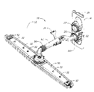
Figure 3 is a perspective view showing the wash tube docked with a
dishwasher fluid manifold and with a spray arm attached to the wash tube.
Figure 4 is a side elevation view of the wash tube coupled to the water
manifold.
DETAILED DESCRIPTION OF THE INVENTION
1U The improved wash tube of the present invention is generally designated in
the drawings by the reference numeral 10. The wash tube 10 has a body 12 with
opposite: t7rst and second ends 14. 1G, respectively.
~Cha tirst end 14 of the wash tube 10 has a bullet shaipe, as best seen in
Figure 1, defined by a curved cap 18. The tirst end 14 has a water inlet 20,
the
substantial portion of which is oriented in a horizontal plane, as best seen
in
Figure 1. The first end 14 is adapted to be coupled to a docking station 22 in
a
water manifold 24 located in the rear wall of the washing chamber of the
dishwasher. The cap 18 directs the water from the water manifold 24 into the
body 12 of the wash tube 10 for delivery to the spray ann s0. The velocity of
the
2 o water flow through the manitbld is thus decreased to substantially zero
when
captured by the cap 18 ofthe wash tube 10, which in turn increases the
watei°
pressure through the wash tube l0. Thus, the water pressure through the spray
on
nozzles 32 is increased for enhanced cleaning for the objects in the racks.
The
curved shape of the cap 18 increases the docking tolerance between the wash
tube
2 _~ 1 U and the opening in the docking station :?2.
As seen in Figure 4, the first end l4 extends through the docking station 22
such that the cap I 8 is in close proximity, or engages, the rear wall 26 of
the
manitbld 24. When the wash tube 10 is docked with the manifold 24, the water
inlet 20 extends perpendicular to the flow of water upwardly through the
manifold
3

CA 02428672 2003-05-13
24. Thus, the cap 18 may engage the inner surface 26 of the manifold 24
without
restricting the flow of water into the wash tube 10.
In Figures 3 and 4, the water manifold 24 is shown as having a lower
opening 2~ anti an upper opening 27. Such a dual opening manifold is provided
in
dishwashers wherein the rack is movable upwardly and downwardly to
accommodate different sued objects to be washed. If the dishwasher has a fixed
upper rack. only a single opening need be provided in the manifold 24 for
docking
with the wash tube l0.
'T'he second end 16 of the wash tube 10 includes a downwardly oriented
water outlet 28, as best seen in Figure 2. The second end 16 is adapted to be
coupled to a wash or spray arrn 3(i in any convenient manner. The coupling of
the
second end 16 of the wash tube 11> to the spray artn 30 allows the spray arm
30 to
rotate by the force of the water sprayed from the spray arm jets or nozzles
32.
The body 12 of the wash tube l 0 is adapted to be mounted or hung from
1 ~ the upper dishwasher rack (not shown) by means of a clip 34. The body 12
also
includes a flexible bellows-type portion to provide t7exibility to the body 12
and
enhance docking with the rnanitold 24. Alignment tabs 38, 40 are shown on the
body 12 and generally are provided to facilitate the manufacturing process for
the
wash tube 10. 'The body 12 is curved along its central portion to accommodate
a
2 0 step down area in the upper rack for holding larger objects.
The invention has been shown and described above with the preferred
embodiments, and it is understood that many modifications, substitutions, and
additions may be made which are within the intended spirit and scope of the
invention. Frown the foregoing, it can be seen that the present invention
25 accomplishes at least all of its stated objectives.
4

Representative Drawing
A single figure which represents the drawing illustrating the invention.
Administrative Status

2024-08-01:As part of the Next Generation Patents (NGP) transition, the Canadian Patents Database (CPD) now contains a more detailed Event History, which replicates the Event Log of our new back-office solution.

Please note that "Inactive:" events refers to events no longer in use in our new back-office solution.

For a clearer understanding of the status of the application/patent presented on this page, the site Disclaimer , as well as the definitions for Patent , Event History , Maintenance Fee  and Payment History  should be consulted.

Event History

Description Date
Application Not Reinstated by Deadline 2010-05-13
Time Limit for Reversal Expired 2010-05-13
Deemed Abandoned - Failure to Respond to Maintenance Fee Notice 2009-05-13
Letter Sent 2008-04-14
Amendment Received - Voluntary Amendment 2008-02-22
All Requirements for Examination Determined Compliant 2008-02-08
Request for Examination Requirements Determined Compliant 2008-02-08
Request for Examination Received 2008-02-08
Inactive: IPC from MCD 2006-03-12
Application Published (Open to Public Inspection) 2003-12-27
Inactive: Cover page published 2003-12-26
Inactive: First IPC assigned 2003-07-17
Application Received - Regular National 2003-06-12
Filing Requirements Determined Compliant 2003-06-12
Letter Sent 2003-06-12
Inactive: Filing certificate - No RFE (English) 2003-06-12

Abandonment History

Abandonment Date Reason Reinstatement Date
2009-05-13

Maintenance Fee

The last payment was received on 2008-04-21

Note : If the full payment has not been received on or before the date indicated, a further fee may be required which may be one of the following

  • the reinstatement fee;
  • the late payment fee; or
  • additional fee to reverse deemed expiry.

Please refer to the CIPO Patent Fees web page to see all current fee amounts.

Fee History

Fee Type Anniversary Year Due Date Paid Date
Application fee - standard 2003-05-13
Registration of a document 2003-05-13
MF (application, 2nd anniv.) - standard 02 2005-05-13 2005-01-20
MF (application, 3rd anniv.) - standard 03 2006-05-15 2006-01-12
MF (application, 4th anniv.) - standard 04 2007-05-14 2007-04-18
Request for examination - standard 2008-02-08
MF (application, 5th anniv.) - standard 05 2008-05-13 2008-04-21
Owners on Record

Note: Records showing the ownership history in alphabetical order.

Current Owners on Record
MAYTAG CORPORATION
Past Owners on Record
JOHN TREVOR MORRISON
ROBERT A. ELICK
Past Owners that do not appear in the "Owners on Record" listing will appear in other documentation within the application.
Documents

To view selected files, please enter reCAPTCHA code :


To view images, click a link in the Document Description column. To download the documents, select one or more checkboxes in the first column and then click the "Download Selected in PDF format (Zip Archive)" or the "Download Selected as Single PDF" button.

List of published and non-published patent-specific documents on the CPD .

If you have any difficulty accessing content, you can call the Client Service Centre at 1-866-997-1936 or send them an e-mail at CIPO Client Service Centre.


Document
Description 
Date
(yyyy-mm-dd) 
Number of pages   Size of Image (KB) 
Description 2003-05-13 4 175
Claims 2003-05-13 3 98
Abstract 2003-05-13 1 23
Drawings 2003-05-13 4 62
Representative drawing 2003-08-11 1 14
Cover Page 2003-12-01 1 46
Description 2008-02-22 4 177
Claims 2008-02-22 3 79
Abstract 2008-02-22 1 21
Courtesy - Certificate of registration (related document(s)) 2003-06-12 1 105
Filing Certificate (English) 2003-06-12 1 158
Reminder of maintenance fee due 2005-01-17 1 109
Reminder - Request for Examination 2008-01-15 1 118
Acknowledgement of Request for Examination 2008-04-14 1 177
Courtesy - Abandonment Letter (Maintenance Fee) 2009-07-08 1 172