Sélection de la langue

Search

Sommaire du brevet 2428672 

Énoncé de désistement de responsabilité concernant l'information provenant de tiers

Une partie des informations de ce site Web a été fournie par des sources externes. Le gouvernement du Canada n'assume aucune responsabilité concernant la précision, l'actualité ou la fiabilité des informations fournies par les sources externes. Les utilisateurs qui désirent employer cette information devraient consulter directement la source des informations. Le contenu fourni par les sources externes n'est pas assujetti aux exigences sur les langues officielles, la protection des renseignements personnels et l'accessibilité.

Disponibilité de l'Abrégé et des Revendications

L'apparition de différences dans le texte et l'image des Revendications et de l'Abrégé dépend du moment auquel le document est publié. Les textes des Revendications et de l'Abrégé sont affichés :

  • lorsque la demande peut être examinée par le public;
  • lorsque le brevet est émis (délivrance).
(12) Demande de brevet: (11) CA 2428672
(54) Titre français: TUBE DE LAVAGE A EXTREMITE CONIQUE POUR LAVE-VAISSELLE
(54) Titre anglais: BULLET ENDED WASH TUBE FOR DISHWASHER
Statut: Réputée abandonnée et au-delà du délai pour le rétablissement - en attente de la réponse à l’avis de communication rejetée
Données bibliographiques
(51) Classification internationale des brevets (CIB):
  • A47L 15/42 (2006.01)
  • A47L 15/22 (2006.01)
  • A47L 15/50 (2006.01)
(72) Inventeurs :
  • ELICK, ROBERT A. (Etats-Unis d'Amérique)
  • MORRISON, JOHN TREVOR (Etats-Unis d'Amérique)
(73) Titulaires :
  • MAYTAG CORPORATION
(71) Demandeurs :
  • MAYTAG CORPORATION (Etats-Unis d'Amérique)
(74) Agent: FINLAYSON & SINGLEHURST
(74) Co-agent:
(45) Délivré:
(22) Date de dépôt: 2003-05-13
(41) Mise à la disponibilité du public: 2003-12-27
Requête d'examen: 2008-02-08
Licence disponible: S.O.
Cédé au domaine public: S.O.
(25) Langue des documents déposés: Anglais

Traité de coopération en matière de brevets (PCT): Non

(30) Données de priorité de la demande:
Numéro de la demande Pays / territoire Date
10/184,405 (Etats-Unis d'Amérique) 2002-06-27

Abrégés

Abrégé anglais


an improved wash tube is provided for a dishwasher. The wash tube is
mounted on the upper rack and has a first end adapted to be releasably docked
with the water manifold in the back of the dishwashing chamber as the rack is
moved between the extended loading position and the retracted wash position.
The inner end of the wash tube includes a curved cap which increases the
docking
tolerance and which presents a substantially downwardly oriented water inlet
to
the wash tube. The cap creates water stagnation adjacent the inlet such that
the
water velocity is substantially reduced and the pressure increased. The second
end
of the wash tube is connected to the spray arm which rotates as water is
ejected
from the spray arm nozzles at increased pressure. The cap allows the wash tube
to
fully dock into the manifold without obstructing the water inlet.

Revendications

Note : Les revendications sont présentées dans la langue officielle dans laquelle elles ont été soumises.


The embodiments of the invention in which an exclusive property or
privilege is claimed are defined as follows:
1. A wash tube for a dishwasher having a wash chamber, a rack movable
between an extended loading position substantially out of the washer chamber
and
a retracted washing position within the wash chamber, a water manifold in a
rear
wall of the wash chamber, and a spray arm for spraying water onto objects to
be
cleaned. the wash tube comprising:
an elongated body having a first end adapted to releasably dock with the
manifold
and a second end adapted to be mounted to the spray arm; and
the first end having a cap to direct water from the manifold to the body.
2. The wash tube of claim 1 wherein the cap is tapered to facilitate docking,
of
the wash tube into the manifold.
3. The wash tube of claim 1 wherein the cap defines a downwardly facing
inlet opening for directing water into the body.
4. The wash tube of claim 1 wherein the cap has rearward edge to limit the
extent of docking of the wash tube into the manifold.
5. The wash tube of claim 1 wherein the cap has a curved upper surface to
reduce the velocity of water flow at the first end of the body and to increase
the
pressure of water in the body.
6. The wash tube of claim 1 wherein the cap extends substantially through
the manifold.
7. The wash tube of claim 1 wherein the body includes a flexible portion to
facilitate docking.
5

8. The wash tube of claim 1 wherein the body includes bellows for flexibility.
9. The wash tube of claim 1 wherein the body is curved along its length.
10. The wash tube of claim 1 wherein the second end of the tube includes a
downwardly directed outlet opening for directing water into the wash arm.
11. A wash tube for a dishwasher having a wash chamber, a rack movable
between an extended loading position substantially out of the washer chamber
and
a retracted washing position within the wash chamber, a water manifold in a
rear
wall of the wash chamber, and a spray arm for spraying water onto objects to
be
cleaned, the wash tube comprising:
an elongated body having a first end adapted to releasably dock with the
manifold
and a second end adapted to be mounted to the spray arm; and
the first end having a downwardly directed inlet opening fur receiving water
from
the manifold.
12. The wash tube of claim 11 wherein the first end is adapted to engage a
back inner surface of the manifold without restricting water flow into the
inlet
opening of the first end.
13. The wash tube of claim 11 wherein the first end extends over the opening
to direct water from the manifold into the inlet opening.
14. The wash tube of claim 11 wherein the first end reduces water velocity and
increases water pressure in the body.
15. The wash tube of claim 11 wherein the body includes a flexible portion to
facilitate docking.
6

16. The wash tube of claim 11 wherein the body includes bellows for
flexibility.
17. The wash tube of claim 11 wherein the second end of the tube includes a
downwardly directed outlet opening for directing water into the wash arm.
18. A wash tube for a dishwasher having a wash chamber, a rack movable
between an extended loading position substantially out of the washer chamber
and
a retracted washing position within the wash chamber, a water manifold in a
rear
wall of the wash chamber, and a spray arm for spraying water onto objects to
be
cleaned, the wash tube comprising:
an elongated body having a first end adapted to releasably dock with the
manifold
and a second end adapted to be mounted to the spray arm; and
the first end being adapted to engage a back inner wall of the manifold
without
restricting water flow from the manifold into the tube.
19. The wash tube of claim 18 wherein the first end has a downwardly directed
inlet opening for receiving water from the manifold.
20. The wash tube of claim 18 wherein the first end reduces water velocity and
increases water pressure in the body.
21. The wash tube of claim 18 wherein the body includes a flexible portion to
facilitate clocking.
22. The wash tube of claim 18 wherein the body includes bellows for
flexibility.
23. The wash tube of claim 18 wherein the second end of the tube includes a
downwardly directed outlet opening for directing water into the wash arm.
7

Description

Note : Les descriptions sont présentées dans la langue officielle dans laquelle elles ont été soumises.

CA 02428672 2003-05-13
BULLET ENDED WASH TUBE FOR DISHWASHER
BACKGROUND OF T'HE INVENTION
Dishwashers typically have upper and lower racks for holding objects to be
washed. Rutatable spray anus a~°e provided in the chamber for spraying
water
unto the objects for cleaning. Often times, one of the spray anus is
positioned
between the upper and lower racks, with a wash tube extending between the
spray
anmu~d the water manifold in the back wall of the washing chamber. The wash
tuba is connected to the upper rack and is adapted to dock to and undock from
the
water manifold, such that the wash tube and spray aan move with the rack
between the extended leading position substantially outside of the wash
chamber
and the r~etractc;d wash position within the wash chamber.
'fhe clucking of the wash tube with the water manitold presents several
problems in the prior art. First, the wash tube must be aligned with the
manifold
opening to allow for proper docking. While a tapered end en the wash tube has
somewhat reduced the docking alignment problem, the flat or planer end of the
wash tube still creates alignment problems.
Secondly, the tlat end of the wash tube defines an opening or inlet which is
in a plane parallel to the water flow in the water manifold. Thus, the t7ow of
water
from the manifold into the wash tube is not efficient. Also, the water in the
wash
2 o tube is nut at optimal pressure.
Accordingly, a prit~~ary objective of the present invention is the provision
of an improved wash tube for a dishwasher which overcomes the problems of tire
prior art.
Another objective of the present invention is the provision of a bullet
2 5 ended wash tLibe to provide improved coupling of the wash tube with the
water
manifold in the rear ofthe dishwasher.
A further objective of the present invention is the provision of a wash tube
having a first end which couples with the manifold, wherein the tirst end
includes
a cup fur directing water from the manifold into the wash tube.
1

CA 02428672 2003-05-13
Still another objective of the present invention is the provision of a wash
tube having a first end with a downwardly oriented inlet.
Another objective of the present invention is the provision of an improved
dishwasher wash tube which increases the water pl°essure from the water
manifold
to the spray artn.
Still another objective of the present, invention is the provision of an
improved dishwasher wash tube which bottoms out on the rear inner surface of
the
water manifold without restricting the flow of water into the wash tube.
~~hese and other objectives will be apparent ti-om the following description
of the invention.
SUM1MARY OF THE INVENTION
An improved wash tube is provided for a dishwasher having a wash
chamber and a rack mruvable between an extended loading position substantially
out cof the wash chamber and a retracted cleaning position within the wash
chamber. The dishwasher has a water manifold in a rear w -all of the wash
clnanober. The wash tube is mounted to the rack, and extends between the water
manifold and a rotatable spray arts for spraying water onto objects to be
cleaned.
The tube has an elongated body with a first end adapted to re;leasably dock
with
the water manitold, and a second end adapted to be mounted to the spray ann.
2 o The tirst end has a bullet-shape so as to provide increased tolerances for
the
docking or coupling of the wash tube with the water manifold. The bullet end
includes a downwardly oriented opening so as to define a cup which directs
water
from the manifold into the wash tube at a reduced velocity and increased
pressure.
The bullet ended wash tube may engage the rear wall of the water manifold
5 without obstructing the inlet opening which is oriented in a plane
perpendicular to
the flow of water through the maniti>ld.
L.

CA 02428672 2003-05-13
BRIEF DESCRIPTION OF THE DRAWINGS
Figure 1 is a side elevation view of the wash tube of the present invention.
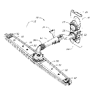
Figure ? is a perspective view ofthe wash tube showing the inlet and
outlet openings of the wash tube.
Figure 3 is a perspective view showing the wash tube docked with a
dishwasher fluid manifold and with a spray arm attached to the wash tube.
Figure 4 is a side elevation view of the wash tube coupled to the water
manifold.
DETAILED DESCRIPTION OF THE INVENTION
1U The improved wash tube of the present invention is generally designated in
the drawings by the reference numeral 10. The wash tube 10 has a body 12 with
opposite: t7rst and second ends 14. 1G, respectively.
~Cha tirst end 14 of the wash tube 10 has a bullet shaipe, as best seen in
Figure 1, defined by a curved cap 18. The tirst end 14 has a water inlet 20,
the
substantial portion of which is oriented in a horizontal plane, as best seen
in
Figure 1. The first end 14 is adapted to be coupled to a docking station 22 in
a
water manifold 24 located in the rear wall of the washing chamber of the
dishwasher. The cap 18 directs the water from the water manifold 24 into the
body 12 of the wash tube 10 for delivery to the spray ann s0. The velocity of
the
2 o water flow through the manitbld is thus decreased to substantially zero
when
captured by the cap 18 ofthe wash tube 10, which in turn increases the
watei°
pressure through the wash tube l0. Thus, the water pressure through the spray
on
nozzles 32 is increased for enhanced cleaning for the objects in the racks.
The
curved shape of the cap 18 increases the docking tolerance between the wash
tube
2 _~ 1 U and the opening in the docking station :?2.
As seen in Figure 4, the first end l4 extends through the docking station 22
such that the cap I 8 is in close proximity, or engages, the rear wall 26 of
the
manitbld 24. When the wash tube 10 is docked with the manifold 24, the water
inlet 20 extends perpendicular to the flow of water upwardly through the
manifold
3

CA 02428672 2003-05-13
24. Thus, the cap 18 may engage the inner surface 26 of the manifold 24
without
restricting the flow of water into the wash tube 10.
In Figures 3 and 4, the water manifold 24 is shown as having a lower
opening 2~ anti an upper opening 27. Such a dual opening manifold is provided
in
dishwashers wherein the rack is movable upwardly and downwardly to
accommodate different sued objects to be washed. If the dishwasher has a fixed
upper rack. only a single opening need be provided in the manifold 24 for
docking
with the wash tube l0.
'T'he second end 16 of the wash tube 10 includes a downwardly oriented
water outlet 28, as best seen in Figure 2. The second end 16 is adapted to be
coupled to a wash or spray arrn 3(i in any convenient manner. The coupling of
the
second end 16 of the wash tube 11> to the spray artn 30 allows the spray arm
30 to
rotate by the force of the water sprayed from the spray arm jets or nozzles
32.
The body 12 of the wash tube l 0 is adapted to be mounted or hung from
1 ~ the upper dishwasher rack (not shown) by means of a clip 34. The body 12
also
includes a flexible bellows-type portion to provide t7exibility to the body 12
and
enhance docking with the rnanitold 24. Alignment tabs 38, 40 are shown on the
body 12 and generally are provided to facilitate the manufacturing process for
the
wash tube 10. 'The body 12 is curved along its central portion to accommodate
a
2 0 step down area in the upper rack for holding larger objects.
The invention has been shown and described above with the preferred
embodiments, and it is understood that many modifications, substitutions, and
additions may be made which are within the intended spirit and scope of the
invention. Frown the foregoing, it can be seen that the present invention
25 accomplishes at least all of its stated objectives.
4

Dessin représentatif
Une figure unique qui représente un dessin illustrant l'invention.
États administratifs

2024-08-01 : Dans le cadre de la transition vers les Brevets de nouvelle génération (BNG), la base de données sur les brevets canadiens (BDBC) contient désormais un Historique d'événement plus détaillé, qui reproduit le Journal des événements de notre nouvelle solution interne.

Veuillez noter que les événements débutant par « Inactive : » se réfèrent à des événements qui ne sont plus utilisés dans notre nouvelle solution interne.

Pour une meilleure compréhension de l'état de la demande ou brevet qui figure sur cette page, la rubrique Mise en garde , et les descriptions de Brevet , Historique d'événement , Taxes périodiques et Historique des paiements devraient être consultées.

Historique d'événement

Description Date
Demande non rétablie avant l'échéance 2010-05-13
Le délai pour l'annulation est expiré 2010-05-13
Réputée abandonnée - omission de répondre à un avis sur les taxes pour le maintien en état 2009-05-13
Lettre envoyée 2008-04-14
Modification reçue - modification volontaire 2008-02-22
Toutes les exigences pour l'examen - jugée conforme 2008-02-08
Exigences pour une requête d'examen - jugée conforme 2008-02-08
Requête d'examen reçue 2008-02-08
Inactive : CIB de MCD 2006-03-12
Demande publiée (accessible au public) 2003-12-27
Inactive : Page couverture publiée 2003-12-26
Inactive : CIB en 1re position 2003-07-17
Demande reçue - nationale ordinaire 2003-06-12
Exigences de dépôt - jugé conforme 2003-06-12
Lettre envoyée 2003-06-12
Inactive : Certificat de dépôt - Sans RE (Anglais) 2003-06-12

Historique d'abandonnement

Date d'abandonnement Raison Date de rétablissement
2009-05-13

Taxes périodiques

Le dernier paiement a été reçu le 2008-04-21

Avis : Si le paiement en totalité n'a pas été reçu au plus tard à la date indiquée, une taxe supplémentaire peut être imposée, soit une des taxes suivantes :

  • taxe de rétablissement ;
  • taxe pour paiement en souffrance ; ou
  • taxe additionnelle pour le renversement d'une péremption réputée.

Veuillez vous référer à la page web des taxes sur les brevets de l'OPIC pour voir tous les montants actuels des taxes.

Historique des taxes

Type de taxes Anniversaire Échéance Date payée
Taxe pour le dépôt - générale 2003-05-13
Enregistrement d'un document 2003-05-13
TM (demande, 2e anniv.) - générale 02 2005-05-13 2005-01-20
TM (demande, 3e anniv.) - générale 03 2006-05-15 2006-01-12
TM (demande, 4e anniv.) - générale 04 2007-05-14 2007-04-18
Requête d'examen - générale 2008-02-08
TM (demande, 5e anniv.) - générale 05 2008-05-13 2008-04-21
Titulaires au dossier

Les titulaires actuels et antérieures au dossier sont affichés en ordre alphabétique.

Titulaires actuels au dossier
MAYTAG CORPORATION
Titulaires antérieures au dossier
JOHN TREVOR MORRISON
ROBERT A. ELICK
Les propriétaires antérieurs qui ne figurent pas dans la liste des « Propriétaires au dossier » apparaîtront dans d'autres documents au dossier.
Documents

Pour visionner les fichiers sélectionnés, entrer le code reCAPTCHA :


Pour visualiser une image, cliquer sur un lien dans la colonne description du document. Pour télécharger l'image (les images), cliquer l'une ou plusieurs cases à cocher dans la première colonne et ensuite cliquer sur le bouton "Télécharger sélection en format PDF (archive Zip)" ou le bouton "Télécharger sélection (en un fichier PDF fusionné)".

Liste des documents de brevet publiés et non publiés sur la BDBC .

Si vous avez des difficultés à accéder au contenu, veuillez communiquer avec le Centre de services à la clientèle au 1-866-997-1936, ou envoyer un courriel au Centre de service à la clientèle de l'OPIC.


Description du
Document 
Date
(aaaa-mm-jj) 
Nombre de pages   Taille de l'image (Ko) 
Description 2003-05-13 4 175
Revendications 2003-05-13 3 98
Abrégé 2003-05-13 1 23
Dessins 2003-05-13 4 62
Dessin représentatif 2003-08-11 1 14
Page couverture 2003-12-01 1 46
Description 2008-02-22 4 177
Revendications 2008-02-22 3 79
Abrégé 2008-02-22 1 21
Courtoisie - Certificat d'enregistrement (document(s) connexe(s)) 2003-06-12 1 105
Certificat de dépôt (anglais) 2003-06-12 1 158
Rappel de taxe de maintien due 2005-01-17 1 109
Rappel - requête d'examen 2008-01-15 1 118
Accusé de réception de la requête d'examen 2008-04-14 1 177
Courtoisie - Lettre d'abandon (taxe de maintien en état) 2009-07-08 1 172