Note: Descriptions are shown in the official language in which they were submitted.
CA 02429350 2008-05-27
SURGICAL INSTRUMENT AND METHOD FOR TREATING
FEMALE URINARY INCONTINENCE
FIELD OF THE INVENTION
The invention relates to a surgical instrument and a method for treating
female urinary
incontinence, that is, the incapacity of controlling the discharge of urine.
BACKGROUND OF THE INVENTION
Urinary incontinence may be caused by a defect function in the tissue or
ligaments
connecting the vaginal wail with the pelvic muscles and pubic bone.
US Patent No. 5,112,344 describes a method for treating female urinary
incontinence
without the necessity of opening the abdomen, which would require extended
hospital care. In
this method a tape is looped around the muscle tissue of the abdomen to either
side of urethra
to be implanted into the soft tissue between the vaginal wall and the
abdominal wall extending
over pubis and with the ends of the tape extending into vagina. The tape is
left in the body in
order that fibrous tissue shall develop around the tape, said scar tissue
functioning as a
supporting ligament in the soft tissue. The tape is removed from the body when
such scar tissue
has developed, which takes about two months.
The result obtained by such surgery is not always satisfactory due to the fact
that fibrous
tissue will not develop sufficiently since the soft tissue between the vaginal
wall and the
abdominal wall is in bad condition.
SUMMARY OF THE INVENTION
The object of the invention is to provide improved and simplified surgery with
a
considerably improved prognosis with regard to restoration of the urinary
continence.
For this purpose the invention provides a surgical instrument for treating
female urinary
incontinence of the kind referred to above, comprising a shank, a handle at
one end of said
shank, a tape to be permanently implanted into the body as a loop around the
urethra, two
curved needle-like elements which are each connected to opposite ends of the
tape, and means
on said shank and each of said elements for exchangeable connection of the
elements one at
the time to the shank at the other end thereof to form at said other end a
curved end portion
CA 02429350 2008-05-27
-2-
dimensioned to extend from the inside surface of the vaginal wall and pass in
front of the pubic
bone to the outside of the abdominal wall.
The invention provides a surgical instrument for treating female urinary
incontinence,
comprising
a) a tape for implanting into the lower abdomen of a female to provide support
to the urethra;
and
b) a curved needle-like element having a proximal end and a distal end and
attach to the tape,
the needle-like element curved over substantially a half of a circle to pass
the tape from an
access in the vaginal wall, under the pubic bone and to the outside of the
abdominal wall.
The invention also provides a method for treating female urinary incontinence
comprising the steps of passing a tape into the body via the vagina first at
one end thereof and
then at the other end thereof at one side and the other, respectively, of
urethra to form a loop
around urethra, located between urethra and the vaginal wall, extending said
tape in front of the
pubic bone and through the lower abdominal wall, the ends of the tape being
available outside
the abdominal wall, adjusting the tape, and leaving the tape implanted in the
body. Preferably
the tape is left permanently in the body to provide itself, as an artificial
ligament, the
reinforcement of the tissue required in order to restore the urinary
continence, and/or to provide
said reinforcement by the development of fibrous tissue.
The invention will be explained in more detail with reference to the
accompanying
drawings which disclose embodiments of the surgical instrument according to
the invention as
well as several surgical steps when practicing the method of the invention
using said surgical
instrument.
In the drawings:
FIG. 1 is an elevation view of the surgical instrument in one embodiment
thereof,
FIG. 2 is a plan view of the surgical instrument of Fig. 1,
FIG. 3 is an enlarged fragmentary axial cross sectional view of a coupling
CA 02429350 2003-05-20
WO 02/39890 PCT/US01/47416
of the instrument for attaching an exchangeable part thereof,
FIGS. 4 to 11 illustrate diagrammatically several surgical steps of the
method according to the invention using the surgical instrument of Fig. 1,
FIG. 12 is an elevation view of the surgical instrument in a second,
preferred embodiment thereof,
FIG. 13 is a plan view of the surgical instrument disclosed in FIG. 12,
FIG. 14 is an exploded side view of one of the needles and tape and
shrinkage hose to be connected with said needle,
FIG. 15 is a side view of the needle in FIG. 14 with the tape connected
1 o therewith,
FIG. 16 is an enlarged fragmentary axial cross sectional view of a modified
coupling of the instrument for connecting exchangeable needles of the kind
shown in FIGS 14 and 15, and
FIG. 17 is a side view of two needles and a tape interconnecting said
needles.
DETAILED DESCRIPTION OF THE INVENTION
Before explaining the present invention in detail, it should be noted that the
invention is not limited in its application or use to the details of
construction and
arrangement of parts illustrated in the accompanying drawings and description,
because the illustrative embodiments of the invention may be implemented or
incorporated in other embodiments, variations and modifications, and may be
practiced or carried out in various ways. Furthermore, unless otherwise
indicated,
the terms and expressions employed herein have been chosen for the purpose of
describing the illustrative embodiments of the present invention for the
The invention discloses an apparatus and method for treating SUI. A tape is
passed through pelvic tissue and positioned underneath the urethra, creating a
supportive sling. The tape provides a structure means for tissue ingrowth and
thereby provides a newly created body tissue supporting means for the urethra.
When pressure is exerted upon the lower abdomen, such as during a cough or
sneeze, the tape provides support to the urethra, allowing it to keep its seal
and
prevent the unwanted discharge of urine.
3
CA 02429350 2003-05-20
WO 02/39890 PCT/US01/47416
The surgical instrument of FIGS 1 to 3 comprises a cylindrical tubulary
shank 10 having at one end thereof a handle 11 which forms two in opposite
directions in a common plane projecting wings 12 and an opening 13. At the
other end of the shank there is a socket 14 which is partly passed onto the
shank
and is soldered or brazed to the shank, a portion of the socket projecting
from the
shank at said other end thereof. A cylindrical shaft 15 is rotatably mounted
in the
shank and can be rotated manually by means of a knob 16 axially knurled at the
outside surface thereof, which is mounted to one end of the shaft and is
received
by opening 13. The other end of the shaft forms a cylindrical portion 17 of
smaller
outside diameter than the shaft, which joins a portion 18 having external
threads,
a smooth end portion 19 of further reduced diameter joining the threaded
portion
18, end portion 19 forming a guide pin at said other end of the shaft.
Portions 18
and 19 are received in the portion of socket 14 projecting from the shank, and
also a shoulder 20 projecting from the shank is received in said portion.
The surgical instrument as described so far is intended to be used several
times and therefore should consist of a material which can be sterilized by
autoclaving, e.g. of stainless steel.
The surgical instrument also includes an exchangeable and disposable
element 21, which will be termed needle. It is attached to the shank at a
straight
portion 21' at one end of the needle and extends over substantially a half of
a
circle to the other, free end thereof in order to pass below the pubic bone
from an
access within the vagina. The needle has circular cross section and has a
smooth, preferably polished outside surface. It tapers slightly towards the
free end
thereof where the needle forms a point 22 by being conical or, as shown,
faceted
but it can also be blunt-ended and have a transversely cut end. The practical
use
of the surgical instrument so far has shown that the conical shape of the
point is
preferred. The disposable needle shall be made either of a tissue compatible
plastics, such as polycarbonate, or of steel or a similar material.
For attachment of needle 21 to shank 10 the needle has at said one end
thereof where the needle forms said straight portion 21' to be received in
socket
14, an axial blind hole extending from the end surface, said hold having a
threaded portion 23 and inwardly thereof a narrower, cylindrical portion 24.
Guide
pin 19 is dimensioned to be guidingly received by said latter portion when the
4
CA 02429350 2003-05-20
WO 02/39890 PCT/US01/47416
threaded portion 18 for attaching needle 21 to the rest of the surgical
instrument
is screwed into threaded portion 23 of the blind hole by rotating shaft 15 by
manual rotation of knob 16, the end surfaces of the shank and the needle being
pressed against each other. The needle should be oriented in a predetermined
rotational position in relation to the shank; it should project at right
angles to the
plane of handle 11 and this rotational position is secured by shoulder 20 on
the
shank being received in a mating recess 25 in the outside surface of the
needle.
Portion 23 of needle 21 instead of being threaded can be dimensioned
such that the threaded portion 18 of shaft 15 cuts a thread in the material of
the
needle when being screwed thereinto.
When the two parts of the surgical- instrument are screwed together in the
manner described they form a rigid unit which can be controlled with great
precision at handle 11 when it is used for surgery by applying the method of
the
invention.
When the method according to the invention is practiced, two needles 21A
and 21 B of the embodiment described shall be connected one at each end of a
tape 26, FIG. 4. The tape end can be glued to the needle but the connection
can be effected also by the tape being passed through an eye 27, FIG. 3, in
the
needle adjacent the end attached to the shank or by the tape end being
connected by uitrasonic welding to the needle or being baked into the plastics
material of the needle at injection molding thereof.
When the surgery for implanting the tape shall start, one needle 21A is
attached to shank 10, the other needle 21 B hanging loosely in tape 26 as
shown
in FIG. 4. In still a further embodiment, needle 21 may comprise quick
attachment and detachment means to enable a single needle use as is disclosed
in co-pending U.S. patent application no. 09/521,801, filed on March 9, 2000,
the
contents of which is incorporated by reference herein in its entirety.
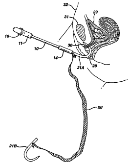
In FIGS. 4 to 11 the relevant parts of the female lower abdomen are
disclosed diagrammatically, the vagina being designated 28, the urinary
bladder
29, the urethra 30, the pubic bone 31, and the abdominal wall 32.
The first step of the surgery for implanting tape 26 is disclosed in FIG. 4
and comprises penetration of the vaginal wall by needle 21A, an incision
having
first been made in said wall, and also penetration of the soft tissue at one
side of
5
CA 02429350 2003-05-20
WO 02/39890 PCT/US01/47416
urethra 30, the needle then according to FIG. 5 being passed close to the
underside of the pubic bone 31 and then through the lower abdominal wall 32.
An incision can be made through the abdominal wall for the passage of the
needle therethrough but if the needle is pointed it may be sufficient to let
the
needle penetrate into the abdominal wall from the inside thereof and to make a
registering incision in the abdominal wall on the outside thereof.
The shank of the instrument is now disconnected from needle 21A, FIG. 6,
by rotating shaft 15 at knob 16 so that the threaded portion 18 of the shaft
is
unscrewed from the threaded portion 23 in needle 21A. Needle 21A is then
withdrawn from the abdominal wall by means of forceps and tape 26 being pulled
into and through the tissue as illustrated in FIG. 7.-
The other needle 21 B is now attached to the shank, FIG. 8, and is passed
through the incision in the vaginal wall to pass through the soft tissue at
the other
side of urethra 30. Needle 21 B is passed below the pubic bone 31 and through
the abdominal wall, FIG. 9, and then, after having been disconnected from the
shank, is withdrawn from the abdominal wall, FIG. 10, all in the same way as
in
the earlier procedure with needle 21A.
Tape 26 is now located at each side of urethra 30 as shown in FIG. 10 and
forming a loop around urethra and located between the urethra and the vaginal
wall, Fig. 11. The surplus of the tape at the outside of the abdominal wall is
cut
off. The tape 26 is left as an implant in the body to form an artificial
ligament and
provides the support for the urethra as required in order to restore urinary
incontinence.
In the embodiment of FIGS. 12 to 17, the end portion 14' of socket 14 is
flattened from opposite sides so that the cross section of said end portion is
non-
circular, and the straight portion 21' of needle 21 at the end to be attached
to
shank 10 is cylindrical but has milled flat faces 21" over that part of said
portion
21', extending from the adjacent end of the needle, which shall be received by
socket portion 14'. The predetermined rotational position of the needle in
relation
to the shank at right angles to the plane of handle 11 is secured by the non-
circular shape of socket portion 14' and the end portion of the needle having
the
flat faces 21 ", which fits into socket portion 14'. The end portion of the
needle
6
CA 02429350 2003-05-20
WO 02/39890 PCT/US01/47416
having the flat faces 21" joins the body of the needle over a conical portion
33,
which tapers towards a shoulder 33'.
In the preferred embodiment, the tape comprises a mesh or netting forming
openings of the order of 1 mm. The openings allow fibroblasts to grow into the
tape to anchor the tape to surrounding tissue. A suitable material for the
tape is
PROLENE , a knitted polypropylene mesh having a thickness of 0.7 mm.
manufactured by Ethicon, Inc., Sommerville, New Jersey, USA. This material is
approved by FDA in USA for implantation into the human body.
Another kind of tape which may be used in the method according to the
lo invention can be knitted or woven more closely than the tape mentioned
above
and can be of such material that the tape aftera shorter or longer period will
be
completely resorbed. By the development of fibroblast proliferation stimulated
by
the tape reinforcement of the tissue required in order to restore the urinary
continence will be obtained.
The material of the tape can be coated with a fibroblast stimulating
substance, e.g. an enamel matrix derivative.
The netting (tape) preferably has a width of approximately 10 'mm and is
enclosed in a thin polyethylene sheath 34 which in flattened condition has
substantially the same width as the tape although a difference in width is
shown in
FIG 14 for clarity of description purposes. The length of the netting should
be
approximately 400 mm. The netting and the sheath may be interconnected by of
means of two rows 35 of stitching as shown although this is not necessary. The
end portion of the sheath is attached to the conical portion 33 of the needle
by
means of a shrink hose 36 of rubber which extends from the shoulder 331 over
the conical portion 33 and partfy over the cylindrical end portion 211 of the
needle. The shrink hose is substantially flush with the surface of the needle
at the
shoulder. By this arrangement the netting is securely attached to the needle
but if
desired the connection can be supplemented by gluing the sheath to portion 33.
The purpose of sheath 34 is above all to facilitate the insertion of the
3o netting in the manner described above i e when the netting is pulled at the
ends
thereof from the vaginal wall to the abdominal skin and to avoid that rough
edges
of the netting irritate or damage the body tissues.
7
CA 02429350 2003-05-20
WO 02/39890 PCT/US01/47416
When the tape has been positioned in the correct position as a sling
around the urethra the polyethylene sheath shall be removed. In order to
facilitate the removal the 'sheath, the sheath can be perforated at the
longitudinal
center thereof as indicated by a dot-and-dash line 37 in FIG. 17. The two
halves
of the sheath can be withdrawn from the body by pulling at the respective
outer
ends thereof the halves being separated at the perforation under the influence
of
the pulling force. As an alternative, the sheath can be made in two halves
that
overlap each other without being interconnected at the longitudinal center of
the netting.
The purpose of the polyethylene sheath is also to protect the netting during
attachment to the needles and during handling before and during insertion into
the body.
The longitudinal center of the tape and sheath should be indicated by a
visible color mark 38, FIG. 17 so that the surgeon readily can see when the
netting
is symmetrically located with reference to urethra during the surgery.
It will be apparent from the foregoing that, while particular forms of the
invention have been illustrated and described, various modifications can be
made
without departing from the spirit and scope of the invention. Accordingly, it
is not
intended that the invention be limited, except as by the appended claims.
8