Note: Descriptions are shown in the official language in which they were submitted.
CA 02429520 2003-05-20
WO 02/42141 PCT/USO1/43075
PRIORITY CAR SORTING IN RAILROAD CLASSIFICATION YARDS USING
A CONTINUOUS MULTI-STAGE METHOD
TECHNICAL FIELD
This invention relates to railroads, particularly to methods of sorting cars
in railroad
yards.
BACKGROUND ART
The purpose of sorting railroad cars is to collect them into "blocks" or
groups of cars
moving together to the next rail terminal, or having commodity, car type or
some other attribute
in common. Once individual cars have been collected into blocks, the blocks
can be assembled
into trains. If a train makes any intermediate stops, blocks are usually
arranged in order of the
sequence of stops, so all intermediate switching can be performed from the
front (or occasionally
the rear) of the train. Armstrong, J. H. (1998) in The Railroad: What It Is,
What It Does: The
Introduction to Railroadi~zg, 4th Edition. Simtnons-Boardrnan Books, Omaha, NE
offers an
excellent introductory text with a section on railroad terminal operations at
pp.197-211.
A railroad "hump yard" utilizes a raised section of track, from which cars are
individually
cut off, and allowed to roll by gravity into their proper classification
tracks. This contrasts with a
"flat yard" where railcars are individually shoved into their proper tracks by
switch engines. In
single stage sorting, only one block is assigned to a track at any point in
time. Multiple stage
sorting builds more than one block on each track simultaneously. Beckmann, M.
J., McGuire
C. B. and Winsten C. B. (1956) in Studies i~ the Economics of Traasportatioh.
Oxford
University Press, London, on pp. 127-171 describe in detail the differences
between hump
versus flat yards, as well as ways their use can be coordinated to minimize
total switching and
delay cost. Troup, K. F., ed. ( 1975) in Railroad Classi,~catiofa Yard
Technology: Ah
Introductory Analysis of Functions arid Operations, Transportation Systems
Center,
Cambridge, MA, (DOT-TSC-FRA-7519), NTIS #PB246724, hereinafter Troup (1975),
developed a "primer" on railroad yard operations. In general, hump yards are
better suited for
classification of railcars one-at-a-time, while flat yards may be more
efficient for large blocks or
"cuts" of cars which remain coupled together during the switching movement.
Very few hump yards have been built in recent years, as railroads have
suffered the loss
of a large portion of their traffic base to trucking competitors. The clear
trend has been towards
closing of hump yards rather than building new facilities; in some cases,
portions of old facilities
remain in use as flat switching yards, as in Russell, KY, Dewitt, NY, and
Enola, PA; in some
cases former hump yards have been converted into intermodal facilities as
happened to Norfolk
Southern's yards in Atlanta, GA and Rutherford, PA; sometimes land has been
released for non-
transportation use, as in Potomac Yard, VA, just a stone's throw away from the
U.S. Patent and
Trademark Office in Crystal City. Many surviving facilities now operate at
close to maximum
throughput and under a state of chronic congestion, to the point that they
often cannot even
accept newly arriving trains, which have to be parked on the main line.
Needless to say, this has
CA 02429520 2003-05-20
WO 02/42141 PCT/USO1/43075
an extreme adverse effect on railroad service reliability, which in turn has
contributed to further
loss of traffic to the trucking industry.
Although computers and new hardware have automated some previously manual
processes -- in particular, control of speed and routing of freely rolling
railcars in hump yards --
the fundamental process of sorting cars and associated facility designs have
changed very little
since hump yards were first invented nearly a century ago. In the single-stage
sorting approach
commonly in use today, each block is assigned its own track. Each car must be
sorted only once,
but the maximum number of blocks built is limited to the number of tracks
available. For
example, a 50-track yard could build a maximum of 50 blocks at one time using
a single stage
approach. Yards designed for single stage sorting need a large number of
tracks, so they can
build the maximum number of blocks possible. Since cars are sorted into many
tracks, individual
tracks can be short. Usually there are not enough tracks to build all needed
blocks, so small
blocks typically have only part-time availability in the yard.
By contrast, multiple stage sorting needs fewer tracks, but each car must be
sorted more
than once. For example, using the "geometric" or "triangular" sorting patterns
(see Figures l and
2), four trains with a total of 29 or 26 blocks, respectively, can be built
simultaneously using
only four tracks. Yards designed for multiple stage sorting need only a few
tracks, but since each
track must hold several blocks at once, tracks should be long enough to hold
an entire train. The
requirement to process cars more than once also implies a need for a high
capacity hump.
Multiple-stage sorting is undeniably a more powerful approach, but in the
United States
the need to process cars more than once has been viewed as costly and
inefficient, so it has not
been commonly applied in practice. Indeed, facilities designed for single-
stage sorting are not
well suited for mufti-stage sorting because of differences in the basic design
parameters for each
kind of yard. But as will be shown herein, in a properly designed facility
multiple-stage sorting
can be not only more powerful, but even more efficient than single stage
sorting because the
costly flat switching operation at the "trim" end of the yard can be
eliminated altogether.
A primary objective of this invention is to provide railroads a practical
means to classify
cars on a priority basis. While some cars don't need to move on any particular
schedule, other
cars have strict delivery deadlines. Although it is always desirable to be
able to increase train
capacity to handle all traffic on a same-day basis, it is not always possible
to increase capacity
nor would it always be economical. So in the event an outbound train has more
cars than it can
carry, it is essential to make certain that any cars having no remaining slack
time in their delivery
commitments have first access to available train capacity.
But today, because of the severely limited capabilities of single stage
sorting, cars are
sorted by destination block only, and not by specific outbound train. The
scheme is essentially
first come first served rather than reflecting the priority of individual
shipments. Some cars not
needing to go may occupy space needed to accomodate higher priority shipments,
resulting in
unnecessary missed connections and service failures.
2
CA 02429520 2003-05-20
WO 02/42141 PCT/USO1/43075
If airlines (like railroads) allowed passengers to board aircraft without
regard to whether
they held tickets for a flight, revenue management would be impossible. The
implications for
railroads should be clear: to take advantage of revenue management technology
which has been
successfully applied by many other industries -- including railroads' direct
competitor, the
trucking industry -- it is essential that classification yard performance be
improved to the level
where connections can be guaranteed to specific trains. Yet, even very recent
published literature
as in Gallagher, J. (1999) Reconsider This, Traffic World, July 12, 1999 on
pp. 32-33 still
holds that "you can't use data in real time to modify the way you handle
individual cars. It's
impractical."
Prior Art Methods of Single Stage Sorting
Traditionally, large hump yards are subdivided into three separate areas, with
tracks
dedicated to specific functions: (a) Inbound trains arrive on the receiving
tracks. Cars are
inspected for mechanical defects and air brakes released so cars can roll
free. (b) To classify an
inbound train, a switch engine couples to the train in the receiving yard and
then shoves cars to
the hump, where they are uncoupled and individually roll into their proper
class~cation tracks
by gravity. (c) Once enough cars have been collected to run an outbound train,
or the scheduled
"close-out" time arrives, blocks of cars are pulled from the "trim" end of the
yard (opposite the
hump) by switch engines arid moved into the departure tracks. There, air hoses
are reconnected,
air brakes charged and tested, and a final inspection of the train is made
before departure. A
typical single stage hump yard design with these three subyards is diagrammed
in Figure 5.
Small yards combine all these functions on the same tracks, so they can be
more flexible
than large facilities; but since small yards usually rely on flat switching,
they are not as efficient
as larger hump yards. Traditional single stage hump yard designs have the
following
shortcomings:
(a) A large number of tracks are required. For each track, switches and car
retarder units
(used for speed control) are required, which are expensive to build and
maintain.
(b) As many classification tracks "fan out" from the hump, the outermost
tracks have sharp
curves, which can bind the wheels of cars causing them to stop short of their
destinations. When
this happens, collisions or derailments may occur; processing must be stopped
and those cars
pushed clear with switch engines. Because of these interruptions, frequent use
of "outer tracks"
reduces the productivity of the humping operation.
(c) Contrary to popular notion, each car must be handled at least twice in a
single stage yard:
first when the car is classified at the hump, then again in a flat switching
movement when cars
are pulled out of the trim end of the yard and moved to the departure yard.
(d) If a needed block has only a part-time assignment, and if that block is
not allocated in the
classification yard when cars come to the hump for it, those cars must be sent
into a temporarily
designated "rehump" track for reprocessing later. Rehump cars must therefore
be handled at least
three times before they finally depart the yard.
3
CA 02429520 2003-05-20
WO 02/42141 PCT/USO1/43075
(e) Since classification tracks are usually too short to make up a whole
train, several tracks
must be assembled at the trim end of the yard to complete each train. If a
train consists of only a
single large block, usually that block will have too many cars to fit into a
single classification
track; it will spill over into additional tracks, thereby reducing the total
number of blocks which
can be built in the yard.
(f) If more than one switch engine is working on the "trim" end at the same
time,
movements of these switch engines can interfere with one another, causing
unproductive delays
and reduction of capacity. Typically, the capacity bottleneck occurs at the
"trim" end of the yard
rather than at the hump. Then, the heavy financial investment in automated
speed control and
switching systems at the "hump" end of the yard cannot be fully utilized due
to the bottleneck at
the trim end of the yard. Effective hump capacity can be increased by
eliminating this bottleneck
at the trim end of the yard, as is proposed by this invention.
(g) All the time cars now spend waiting in the classification yard (typically
12-24 hours) is
wasted. Since other cars may be routed into any track at any time {impacting
standing cars), it is
not safe for mechanical personnel to inspect or repair cars while they lie in
the classification
yard. Mechanical inspection and repair activities are typically performed in
either the receiving or
departure yards, adding directly to the total time required to process cars
through the terminal.
This invention will show how time spent in the classification yard can be
effectively utilized in a
multiple stage yard.
Prior Art Methods of Priority Based Classification
All known methods of priority based classification rely on traditional single
stage sorting.
All these techniques have serious drawbacks. Three different methods can be
used to classify
cars for specific trains:
(a) The most commonly accepted method is to sort cars at the "hump" in the
usual way
(only by destination block), then select specific cars for each outbound train
at the "trim" end of
the yard, This is known as "cherry picking" in the railroad industry. In
Figure 6A from O.K.
Kwon's Ph. D. Dissertation (1994) Managing Heterogeneous Traffic on Rail
Freight Network
Incorlaoratircg the Logistics Needs of Market Segfrcehts, Dept of Civil and
Environmental
Engineering, Massachussetts Institute of Technology, pg. 103, the object is to
extract a specific
car (or group of cars) #1, which are "buried" behind another group of cars #3.
Taking group #1
instead of #3 entails extra switching work because it is necessary to first
move #I to another
track (Figure 6B), then put #3 back to the original track (Figure 6C). This
doubles the amount
of switching work as compared to only taking "first out" cars #3.
The advantage of "cherry picking" is to defer decision making until the latest
possible
time, when the choice of available cars is known for sure; but the method is
extremely costly to
implement since the "trim" end of the yard is designed for flat switching
large blocks of cars, not
for sorting by individual car. Digging oul priority cars at the trim end of
the yard exacerbates the
4
CA 02429520 2003-05-20
WO 02/42141 PCT/USO1/43075
capacity bottleneck which already exists there, and reduces throughput of the
whole facility. For
these reasons, cherry picking is not considered cost effective by the railroad
industry.
(b) A second approach performs all individual car selection at the "hump,"
which is better
designed for this kind of work, rather than trying to accomplish it at the
trim end of the yard. It
can be done by diverting a sufficient number of low priority cars away from
their primary
classifications into "rehump" tracks instead, so that remaining train capacity
is just sufficient to
take all high priority cars. To implement this, train capacity must be known
in advance, which in
turn may require determining locomotive assignments well ahead of time. The
main disadvantage
is that this approach may require committing to decisions up to 12-24 hours
prior to the
scheduled train departure time. Afterwards, if a planned inbound train does
not arrive on time or
with all its cars, or if more mechanical defects are discovered than
anticipated, it may be hard to
get the excess diverted cars back onto the outbound train in time.
(c) To reduce the number of rehump cars, an adaptation of method (b) from
Kraft,
E. R. (1995) Uhio~ Paci,~CC Railroad's Terminal Prz~rzty MovemefZt Planner,
Working Paper,
Union Pacific Railroad, Omaha, NE, tries to find classification track
assignments to start new
blocks immediately rather than automatically diverting excess cars into a
rehump track. The
decision to divert low priority cars is still required as early as before. The
approach makes very
intensive use of every available inch of classification track space, but also
tends to widely scatter
blocks for the same outbound train across the entire yard, requiring frequent
"crossover"
movements for train assembly at the trim end. Outbound blocks must be trimmed
in strict order
and absolutely by the scheduled time; otherwise, the whole block to track
assignment plan falls
apart. The approach relies on very precise adherence to both inbound and
outbound train
schedules. But even with tight adherence to schedules, there are still
distinct advantages to
postponing as long as possible a final decision on the exact makeup of the
outbound train.
Prior Art Methods of Multiple Stage Sorting
Multiple stage sorting methods have been described by M. W. Siddiquee (1971)
in
Investigation of Sorting and Train Formation Schemes for a Railroad Hump Yard,
in Traffic
Flow and Transportation, Proceedings of the Fa, fh Inter~eational Symposium oa
the Theory of
Trafj"-CC Flow ahdTranspartatioh, June 16-18, 1971, G. F. Newell, editor,
American Elsevier
Publishing Company, New York. (hereinafter known as Siddiquee, 1971) and by
Daganzo, C.
F. et al. (1983) Railroad Classification Yard Throughput: The Case of
Multistage Triangular
Sorting, Trahsportatioa Research A,17A (2) 95-106 (hereinafter known as
Daganzo, 1983), as
well as by several other authors. No mention of sorting cars by priority has
been found in any
prior art references on multiple stage sorting. Siddiquee (1971) defines four
sorting methods --
by train; by block; geometric and triangular sorting -- but these last two are
very closely related,
and do not constitute significantly different methods for organizing railroad
yard operations.
CA 02429520 2003-05-20
WO 02/42141 PCT/USO1/43075
(a) The "Sorting by train" method initially collects cars by outbound train,
intermixing cars
for each train in no particular block order on a single classification track.
Those cars are later
pulled back to the hump and sorted into speck blocks needed for the train
being made up.
Finally, blocks must be assembled into proper standing order sequence for
departure. This
requires a minimum of three handlings per car (including the flat switch at
the trim end of the
yard) making it noncompetitive with other approaches, unless a special
herringbone track
arrangment is used (see figure 7). By providing intermediate crossover tracks,
a herringbone
arrangement allows assembly of a train carrying more than one block of cars on
a single
departure track, without needing to flat switch cars from the trim end of the
yard. This reduces
the number of car handlings to only two, but a specialized track layout is
needed to achieve it.
Technically, cars can be sorted into a hernngbone track using only single
stage sorting,
but construction and maintenance costs of herringbone tracks are so high that
Garners generally
cannot afford to build a sufficient number of them. If blocks needed for the
outbound train are
not being built in the herringbone tracks when cars come to the hump,
according to N.
Miyakawa ( 1972) in Automation of Koriyama Marshalling Yard and the
Herringbone Track. Rail
Intematiohal 1972 (5) 300-320, those cars must be sent into a rehump track
instead. To
increase utilization of the herringbone tracks, they can be used in the two-
stage manner just
described. However since Japanese National Railroad did not initially sort by
outbound train as
suggested here, some rehump cars had to be processed more than twice.
(b) The "Sorting by block" method (also called arithmetic or rectangular
sorting) intermixes
cars of several trains, different blocks of the same train are never
intermixed on the same track.
As shown in figure ~, cars from the first block of each train are intermixed
on the first track, cars
from the second block of each train are intermixed on the second track, and so
on. Just prior to
train departure, the cars are resorted by outbound train, simultaneously
assembling several trains
with all blocks in proper sequence for departure.
Sorting by block inherently requires no more work than conventional single
stage
sorting, only two handlings per car. However, in a traditional hump yard,
classification tracks
are usually too short, so several tracks would be required to hold all the
cars for each train. Due
to this design flaw, outbound trains still need to be assembled in the
departure yard by flat
switching out of the "trim" end, forcing an unnecessary third handling for
each car. This extra
handling results entirely from trying to perform multiple stage sorting in a
facility not properly
designed for it. It also leads to the myth that multiple stage sorting is more
costly than
conventional single stage processing. To the contrary, the issue is simply one
of optimizing
facility design to its intended use, but once a yard has been constructed --
for better or for worse
-- this does tend to "lock in" the operational method for which the facility
has been originally
designed.
The greatest weakness of sorting by block is the requirement either that all
first stage
tracks must be completely cleared prior to commencement of second stage
sorting (requiring a
6
CA 02429520 2003-05-20
WO 02/42141 PCT/USO1/43075
very long switching lead to hold all the cars from several tracks at once); or
that second stage
sorting must use different tracks than those used for the first stage sort (as
in a "folded" or "two
stage" design, L. C. Davis (1967) The Folded Two Stage Classification 3.'aYd,
MBA Thesis,
Wharton School, University of Pennsylvania, Philadelphia, PA, hereinafter
known as Davis,
1967). This practically restricts "sorting by block" to assembly of only short
local trains, or to
detailed makeup of trains carrying a very large number of small blocks.
(c) "Geometric" and "Triangular" sorting are based upon a pattern of arranging
blocks which
allows intermixing blocks of the same train on the same track; by resorting
each track in turn on
top of other cars (without requiring all tracks be cleared at once) several
trains may be assembled
simultaneously in correct block sequence for departure. According to K. J.
Pentinga ( 1959)
Teaching Simulaneous Marshalling, The Railway Gazette, May 22, 1959, pp. 590-
593, the
triangular pattern was adapted from the geometric pattern by the French
National Railways
(SNCF) so that no car must be sorted more than three times -- but track
assignments for the first
six blocks are identical (see Figures l and 2). For more than six blocks,
geometric sorting
requires slightly fewer tracks, but this savings in tracks is accomplished at
the expense of an
increase in the total number of cars rehandled. For the purpose of this
invention, since very few
trains carry more than six blocks at one time, the geometric and triangular
patterns will be seen to
be practically equivalent.
According to Pentinga (p. 591), the "Geometric" sorting pattern is so named
because
block numbers assigned to each track corresponds to a geometric series of
numbers, with a
common multiplier of two (e.g. for track l: 1, 2, 4 , 8 = 1 x 2~, 1 x 21, 1 x
22, 1 x 23; for track
2: 3, 6, 12 = 3 x 2~, 3 x 21, 3 x 22; for track 3: 5, 10 = 5 x 2~, 5 x 21.)
Blocks on the first train
are numbered 1, 2, 3, etc. Blocks on the second train are numbered 3, 4, 5, 6,
etc. Blocks on
the d'th train are numbered 2 (d- 1) + l, 2 (d- 1) + 2, 2 (d- 1) + 3, etc.
Classification track "k"
is assigned all blocks having the following indices:
bk;~=(2(k-1)+1)2U-1)
where bk,~ is the j'th lowest block number assigned to track k.
Mathematical equations describing the "Triangular" sorting pattern are given
by Daganzo
(1983, pg. 98, eqn. 8, 9a and 9b). Following Daganzo, blocks on the first
train are numbered l,
2, 3, etc. Blocks on the second train are numbered 2, 3, 4, etc. Blocks on the
d'th train are
numbered d (d- 1) / 2 + l, d (d- 1) / 2 + 2, d (d- 1) / d + 3, etc.
Classification track "k" is
assigned all blocks having the following indices:
bk,l=k(k-1)/2+ 1
bkj=k(k-1)/2+jk+1+(j-1)(j-2)/2, j=2,3,4...
7
CA 02429520 2003-05-20
WO 02/42141 PCT/USO1/43075
where b~,i is the j'th lowest block number assigned to track k. However, a
much simpler
method of describing the Trangular sorting pattern is shown by Davis (1967,
pg. 52, Fig 3-7) .
Davis' figure is reproduced below as Table 2. To generate the triangular
pattern, block numbers
are simply arranged left to right, skipping over the position that would
normally be used for the
second block assignment to each track.
Tracks
A B C D E F
Classification I 1
Identifications I - 2
Assigned ~ 3 - 4
6 - 7
8 9 10 - 11
12 13 14 15 - 16
17 18 19 20 21 -
Table 2
Prior Art
Adopting Siddiquee's notation, in all drawing figures depicting car movements,
parenthesis indicate intermixed groups of cars, but an alphabetic prefix
indicating the specific
outbound train has been added. For example, (A1 A2 A3) indicates that cars for
the first three
blocks assigned to train "A", may be randomly intermixed together on the same
track. By
contrast, (A1) (A2) (A3) indicates that cars for blocks 1,2,3 have been
separated into three
distinct cuts, following one another in proper standing order on the track and
that cars of each
block are not intermixed. The notation (A2) (Al) (A3) shows blocks 2, 1 and 3
separated, but
not in proper train standing order. These cars would have to be put into
proper block sequence
either (Al)(A2)(A3) or (A3)(A2)(Al) by flat switching, depending whether the
train was
intended to depart to the left or right. The first block of any train always
follows immediately
behind the locomotive, with subsequent blocks in ascending numerical sequence.
For train "A" with six blocks, the desired outcome is:
(A1)(A2)(A3)(A4)(A5)(A6) for a
train departing to the left: this indicates all cars needed for the train have
been separated into
distinct blocks (cars not intermixed) and all lined up on one track in proper
sequence for
departure. To simplify the notation, only one representative car for each
block is shown in each
example. H. B. Christianson, Should Future Yards Classify Freight in Two
Stages? Railway
Management Review 72 (2) A20-A32 (hereinafter known as Christianson, 1972)
specifically
8
CA 02429520 2003-05-20
WO 02/42141 PCT/USO1/43075
addressed this issue with several examples, demonstrating that the sorting
process still works if
more than one car is included in each block.
Figures l and 2 show initial block to track assignment patterns to
simultaneously build
four trains on four tracks using prior art geometric and triangular sorting,
respectively. For easy
comparison to past published references, Siddiquee's block-numbering scheme is
used in both
figures. In Figure 1, blocks l, 3, 5, 7 and 9 for each train are assigned to
track 1; blocks 2, 6,
and 10 are assigned to track 2, block 4 is assigned to track 3, and block 8 is
assigned to track 4.
Using Siddiquee's notation, same-numbered blocks for different trains are
always assigned to
the same tracks; but this can be confusing since the block numbering sequence
does not always
begin at one for every train. Blocks of train A are numbered 1 thru 10; but
train B is numbered
2 thru 10, train C is 4 thru 10, and train D is 8 thru 10.
Such notation would be confusing in later figures, which present continuous
sorting
patterns. Introducing the notation which will be used throughout the remainder
of this
application, in Figure 3A, blocks are renumbered so every train always starts
with block #l.
Blocks of train B are renumbered 1 thru 9; train C is 1 thru 7 and train D is
1 thru 3. Block to
track assignment patterns shown in Figure 3A and Figure 2 are actually the
same, but Figure 3A
uses the new block numbering sequence, which is used in the remainder of this
application.
Figures 3B thru 3E work through a complete sequence of switching cars using
the prior
art triangular sorting method. This prior art pattern assembles all four
trains simultaneously, so
these trains should all be scheduled to depart close to the same time. A
detailed step-by-step
explanation of the sorting process follows. In later figures, including ones
showing continuous
sorting processes, each track is similarly sorted in turn and each drawing
figure shows the result
after the completion of each sorting step. A textual description is only
provided (below) tracing
the steps of Figures 3A-3E, but for every series of drawing figures depicting
car movements, a
table is provided summarizing the sequence of car movements needed to carry
out the sorting
process. For ease of comparison, each table is numbered the same as the set of
drawing figures
to which it relates, even though in some cases this results in tables being
shown here out of
numerical order. For example, Table 3 below describes the sequence of railcar
movements
shown in drawing figures 3A-3E.
The initial yard setup is shown in Figure 3A. This configuration of block to
track
assignments would be maintained for most of the day (perhaps 20 hours) while
arnving inbound
trains are processed, and cars for all four trains are collected in the
classification tracks.
When departure time approaches, outbound train assembly is started by
retrieving the
contents of Track #1 and pulling those cars back to the hump. These cars are
reswitched as
follows: Al- to Track 1 by themselves, A3 and B2 to track 2, on top of cars
already there; A5,
B4 and C2 to track 3, on top of cars already there; and A8, B7, C5 and D2 to
track 4. The
result, shown in Figure 3B has cars for block (A1) isolated by themselves on
track 1, while cars
on the other three tracks are segregated into two distinct groups of blocks,
and cars are not
intermixed between distinct groups.
9
CA 02429520 2003-05-20
WO 02/42141 PCT/USO1/43075
First Stage Setup A1,A3,AS,A8,B2,B4,B7,CZ,CS,D2 to Track
shown in 1
Figure 3A A2,A6,A9,B1,BS,B8,C3,C6,D3 to Track 2
A4,A10,B3,B9,Cl,C7,D4 to Track 3
A7,B6,C4,D1 to Track 4
Pull Back Track 1 A1 to Track 1
from the right
side, and reclassifyA~,B2 to Track 2
as follows.
Outcome shown in AS,B4,C2 to Track 3
Figure 3B.
A8,B7,CS,D2 to Track 4
Pull Back Track 2 A2,A3 to Track 1
from the right
side, and reclassifyBl,B2 to Track 2
as follows.
Outcome shown in A6,BS,C3 to Track 3
Figure 3C.
A9,B8,C6,D3 to Track 4
Pull Back Track 3 A4, AS,A6 to Track 1
from the right
side, and reclassifyB3,B4,B5 to Track 2
as follows.
Outcome shown in C1,C2,C3 to Track 3
Figure 3D.
A10,B9,C7,D4 to Track 4
Pull Back Track 4 A7,A8,A9,A10 to Track 1
from the right
side, and reclassifyB6,B7,B8,B9 to Track 2
as follows.
Outcome shown in C4,CS,C6,C7 to Track 3
Figure 3E.
All four trains are D 1,D2,D3,D4 to Track 4
ready for
departure towards
the left.
Table 3
Prior Art
Next, track 2 is retrieved. The entire track is pulled back to the hump,
including all cars
just sent in from reprocessing of the first track. These cars are routed as
follows: A2 and A3 to
Track l, B1 and B2 to Track 2, A6, B5 and C3 to Track 3, and A9, B8, C6 and D3
to Track 4.
The result, shown in Figure 3C has (Al ) (A2) (A3) assembled in proper order
on track 1; since
blocks (A2) and (A3) were not intermixed on track 2, they will not be
intermixed when those
cars are collected on track l; and train B is started on track 2. Cars on the
other two tracks are
segregated into three distinct groups of blocks, whereby cars are not
intermixed between groups.
Track 3 is then reprocessed in a similar fashion. As shown in Figure 3D, cars
on track 4
are segregated into four distinct groups of blocks. By reprocessing this last
track, all four trains
are simultaneously assembled in proper standing order, without requiring use
of more than four
tracks at any time. The final result is shown in Figure 3E.
Note that a six block train could be built using a block to track assignment
pattern for
seven (or more) blocks, simply by assuming that some blocks have no cars .
This is shown in
CA 02429520 2003-05-20
WO 02/42141 PCT/USO1/43075
Figures 9A thru 9D, where the position normally reserved for the third block
has no cars, so
subscripts 4-7 have been resequenced as 3-6, respectively. Table 9 below
describes the sequence
of railcar movements shown in drawing figures 9A-9D. Thus, the geometric
pattern could be
derived from the triangular pattern, and vice versa, simply by skipping some
intermediate block
positions. For the purpose of this invention these two patterns are treated
as, in fact, equivalent
as well as any variations which cart be constructed by simply skipping
intermediate block
positions.
First Stage Setup Al,A4,A6 to Track 1
shown in
Figure 9A A2,A5 to Track 2
A3 to Track 3
Pull Back Track 1 A1 to Track 1
from the right
side, and reclassify A4 to Track 3
as follows.
Outcome shown in FigureA6 to Track 2
9B.
Pull Back Track 2 A2 to Track 1
from the right
side, and reclassify AS,A6 to Track 3
as follows.
Outcome shown in Figure
9C.
Pull Back Track 3 A3,A4,AS,A6 to Track 1
from the right
side, and reclassify
as follows.
Outcome shown in Figure
9D.
All four trains are
ready for
departure towards
the left.
Table 9
Another improvement results from simply taking advantage of triangular
sorting's
capability to build trains in proper block standing order. In triangular
sorting, cars assigned to a
"head block" slot (the first block in standing order sequence on each track)
are handled twice,
whereas other cars must be handled three times. Therefore, Daganzo (1983)
suggests blocks
with the largest number of cars should be assigned to "head block" slots to
minimize the number
of cars rehumped. But if that is done, the order of the blocks must be
rearranged by flat
switching before the outbound train can depart. Doing this might make sense in
a traditionally
designed yard where cars must be trimmed out anyway -- but clearly in a new
facility the benefit
of completely eliminating the trim operation would outweigh the cost of
rehumping a few
additional cars, given that the basic design of a mufti stage sorting facility
must provide for a
very high capacity hump and an effective car speed control system. Although
the extension to
sequence blocks strictly in the order required by the transportation plan may
seem obvious, prior
literature teaches against the practice.
11
CA 02429520 2003-05-20
WO 02/42141 PCT/USO1/43075
Additional Prior Art Citations
A number of prior art citations are furnished with this Patent application
which are not
otherwise discussed in the specification. This section provides a brief
discussion of each of those
citations. It is hoped that future researchers may benefit by having a
comprehesive survey of
prior literature in multiple stage switching techniques.
Herbert T. Landow published a series of two articles, as Overseas Railroads
Try New
Yard Techniques (Part I), pp 95-100, and Train Blocks and Herringbones (Part
II), pp 101-102,
both in September 1968 Modern Railroads. The first article discusses several
means of car
retardation and car mover devices and how these can be used to improve yard
efficiency, but Part
I does not discuss multiple stage switching techniques. Part II describes
herringbone track
layouts (as shown in Figure 7) and prior art geometrical and triangular
switching techniques. A
third article by Landow, in Yard Switching with Multiple Pass Logic, Railway
Management
Review, Vol. 72 No. 1, pp 11-23 uses difficult notation which is hard to
follow. However
Landow's context (p 16) is that "Simultaneous switching is applicable in any
case where two or
more trains are to be sent out of a yard at or near the same time." This
restriction is clearly
associated with the prior art method of batch sorting of trains. None of these
papers address
either the continuous approach to multiple stage sorting, as this invention
does, nor do they
discuss the ability to use multiple stage sorting to preselect particular cars
if an outbound train
exceeds capacity.
Hoppe, C. W. ( 1972) in Do We Need Yards? Railway Management Review, Vol 72
No. 2 pp Al-A6 discusses general problems associated with prior art designs
for railroad
classification yards. Hoppe's article has a very short section an multiple
stage switching
techniques concluding (p A5) "It does little good to design a yard with great
potential if the men
who are going to run it are not trained to run it." Christianson ( 1972), as
cited previously,
examines several real-world yard configurations, finally concluding, "no large
two-stage yard
operation exists anywhere in the world." A later article by Christianson, H.
B., et al (1979) in
Committee 14 -- Yards and Terminals, Report on Assignment 7, Yard System
Design for Two
Stage Switching, American Railway Engineering Association, Proceedings 79Th
Annual
Conference, Vol 81, pp 145-155, repeats much of the material from
Christianson's 1972 article
but concludes "One alleged disadvantage is that personnel cannot learn and
effectively use two-
stage switching, but a seven-day test at a large flat yard and a two-day
experiment at a medium-
sized hump yard refuted this. Two staging will work in a normal environment
with normal
delays and problems." Neither of Christianson's papers offer any improvement
to the basic
techniques of two stage switching, as this patent application does.
Rao, M.S. (1976) in Switch Back Hump - A New Marshalling Tool, Rail
International
1976, No. 4, pp 219-222 proposes to use a steep gradient to cause cars
actually to reverse
direction and then be routed into a secondary sorting yard. Rao proposes to
utilize multiple stage
switching techniques to maximize the productivity of his switch back hump. The
novel aspect of
12
CA 02429520 2003-05-20
WO 02/42141 PCT/USO1/43075
Rao's paper is the reversal of direction which cars undergo during the humping
process;
however Rao offers no improvements to prior art multiple stage switching
techniques. Rao's
paper also appears as a prior art citation in U.S. Patent 4,766,815 to
Chongben et al (1988).
Chongben proposes using a section of ascending gradient only to reduce car
speeds rather than
to actually reverse the cars' direction, as Rao does. Chongben's patent does
not address multiple
stage switching but only the design of the car retarder systems in the yard.
Middleton, W. D. (1979) in New Approaches to Yard Automation in Japan, Railway
Age, February 12, 1979, pp. 46-49, does not discuss multiple stage switching
techniques, but
this citation is provided as a further reference on the Japanese National
Railroad's use of
Herringbone tracks and car retarder systems. Koehn, K., Holt, H. L. and
Sabeti, A. (1972) in
European Yard Retarder Systems, Railway Management Review, Vol 72 No. 2 pp A7-
Al9
offer a survey of many different kinds of car retarder systems, which provide
an alternative to
the traditional "clasp" retarder systems (as in U.S. Patent 5,388,525 to
Bodkin, 1993) now
widely used in the United States.
Welty, G. (1980) in Outlook: Fewer Yards, Faster Output, Railway Age, October
13,
1980, pp. 16-17, surveys the then-current state of the art in railroad
classification yard
technology. He states, "First, discard the radical. Linear-designed yards may
work overseas,
but experts who have looked at these and other nonstandard yards say that they
simply don't
meet the requirements of railroading in North America. Thus, the new
classification yards of
tomorrow, like those of today and yesterday, will have the standard components
-- receiving
yard, class yard, and departure yard, either inline or wraparound, depending
mostly upon the
constraints of available space." This teaches against the current invention.
The ability to
successfully implement "non standard" yards in North America was later
reported by Welty in At
Livonia, An Early Payoff, Railway Age, February 1995, pp 41-42, describing a
successful
application of the "Dowty" retarder system at Union Pacific's yard at Livonia,
LA, one of the
very few new classification yards constructed anywhere in North America during
the 1990's.
Kraft, E. R. and Guignard-Spielberg, M. (1993) in A Mixed Integer Optimization
Model
to Improve Freight Car Classi, fication in Railroad Yards, Report 93-06-06,
Department of
Operations and Information Management, The Wharton School, University of
Pennsylvania,
propose to simultaneously optimize both hump sequence and dynamic block to
track assignments
using a network-based, mixed integer math programming formulation. Using a
decomposition
approach, Wang, X. (1998) in Improviyzg Plan~zircg for Railroad Yard, F~restry
arcd
Distributio>z, Ph. D. Dissertation, Department of Operations and Information
Management, The
Wharton School, University of Pennsylvania, was able to scale up Kraft and
Spielberg's
approach to solve a realistically sized problem within a reasonable time
frame. However, Kraft's
formulation was only tested using a "toy" problem of 3 trains, 4 time periods,
3 blocks and 2
tracks, not practical for any real applications. In order to solve the
problem, Wang adjusted some
constraints so that they may no longer represent a feasible solution to Kraft
and Spielberg's
original problem. Both the Kraft and Spielberg (1993) and Wang (I998)
formulations attempt to
13
CA 02429520 2003-05-20
WO 02/42141 PCT/USO1/43075
preselect cars for specific outbound trains; but both rely on single stage
sorting techniques in
traditional hump yard facilities; they do not use any multiple stage sorting
techniques as
advocated by this invention.
DISCLOSURE OF THE INVENTION
In accordance with the present invention, outbound trains are built in proper
standing
order for departure directly from the classification tracks, using a
continuously sustainable multi-
stage sorting process. During this process, cars are easily separated based on
priority or
according to their delivery time commitments, so connections of cars needing
to go on a specific
train can be protected. During second stage sorting operations, cars may be
inspected or repaired
while they await outbound connections in the classification tracks,
effectively utilizing otherwise
idle time and resulting in considerable savings in time required to pass
through the yard. This
may be accomplished in a traditional rail yard setting, but will yield even
more benefit if
accomplished in one of the specialized facility designs shown in the drawing
figures.
Objects and Advantages
Accordingly, several objects and advantages of the present invention are:
(a) The continuous multiple stage sorting process utilizes terminal resources
more uniformly
and thus efficiently than~prior art methods.
(b) If more cars are available than the capacity of the outbound train, the
decision which
specific cars to take is not required until immediately before train
departure, rather than 12-?~
hours in advance as with some prior art single stage sorting methods.
(c) Tracks can be used for more than one purpose, allowing flexible use of
assets and
eliminating unnecessary movement of cars within the yard. Single car sorting
is efficiently
performed at the hump. Preblocked groups of cars may be conveniently
transferred from one
train to another by flat switching at the opposite end of the yard -- without
requiring preblocked
cars to be unnecessarily reprocessed over the hump or moved a long distance in
a special flat
switching transfer, as current yard designs do.
(d) Yard designs proposed here, particularly the preferred embodiment, utilize
a very simple
track layout, offering a distinct possibility that new yards could be
constructed to an essentially
standardized design, with only minor variations such as the exact length and
number of tracks
needed in each yard. Computer software needed for both yard design and process
control can be
standardized across many facilities, rather than having to be heavily
customized for each
individual yard. The guesswork can be eliminated from yard design by utilizing
such
standardized computer simulation tools to ensure facilities are properly
sized.
(e) Assembly of outbound trains by flat switching at the trim end of the yard -
- and the
related capacity bottleneck -- are completely eliminated. One additional hump
operation is
required to replace the flat switching which now occurs at the trim end of the
yard. However,
this poses no inherent difficulty provided the hump is designed with
sufficient capacity to
accomplish its intended workload. Since the hump operation should actually
proceed faster than
14
CA 02429520 2003-05-20
WO 02/42141 PCT/USO1/43075
the trim operation it replaces, the net effect should be a savings in
operating cost per car
.classified, as well as in the capital construction and maintenance costs of
the yard facilities
themselves.
(f) The total number and aggregate length of tracks needed in the yard is
considerably
reduced. The need for separate receiving and departure yards is eliminated
altogether. In the
classification yard, instead of many short tracks (for example, 60 tracks up
to 40 cars long), only
a few long tracks must be built (for example, 15 tracks up to 150 cars long.)
Fewer tracks need
fewer switches and retarder units (for controlling car speeds) to construct
and maintain.
Compared to conventional hump yard designs, proposed new mufti-stage yards
will be
considerably more economical to construct, maintain and operate.
(g) With fewer classification traclcs, a relatively straight path can be
constructed from the
hump into any of the tracks, and the distance is reduced from the hump to the
clearance point of
the farthest classification track. This improved geometry raises the
probability a car will at least
roll clear of the switching area, thereby increasing the capacity and
throughput of the humping
operation. Many multiple car cuts are humped, especially during second stage
sorting. Hydraulic
car retarders, well known as "Dowty" units -- see A. W. Melhuish (1983)
Developments in the
Application of the Dowty Continuous-Control Method, Transportation Research
Record 927 pp.
32-38 (hereinafter Melhuish, 1983); D. E. Bick (1984) A History of the Dowty
Marshalling
Yard Wagon Control System, Proceedings of the Institute of Mechanical
Engi~zee~s 198B (2)
19-26 ( hereinafter Bick, 1984); and I1.S. Patent 5,092,248 to Parry (1992) --
are well suited to
accomodate the requirement for processing multiple car cuts, and this retarder
system can
provide continuous speed control for very long classification tracks as well.
As compared to
conventional single stage hump yards --where cars are nearly always sorted one-
at-a-time and
where the humping process is subject to frequent interruptions -- excellent
geometry and frequent
processing of cars in multiple car groups should substantially increase the
hump processing rate.
Another benefit of the Dowty retarder system is practical elimination of
lading and railcar damage
by preventing overspeed coupling impacts in yards.
(h) Inspection and servicing of cars while they wait for connections on
classification tracks
may save perhaps 5-10 hours in the average time required to process cars
through the yard. This
practice also permits more efficient utilization of mechanical forces by
allowing their activities to
be spread uniformly throughout the day, rather than unduly determining
maintenance personnel
needs based on (often highly peaked) train arrival and departure patterns.
(i) Figure 4 shows the potential to bypass intermediate terminal handlings, by
improving
sorting capabilities at railyards which originate and terminate a sufficient
volume of local traffic
(in the vicinity of 1000 cars per day total). Currently, such yards often have
only "flat"
switching capability, so it is more efficient to send cars to a nearby "hump"
yard for detailed
individual car classification. By converting from flat switching to a multiple
stage hump yard
design, as proposed here, cars may be economically sorted at the originating
yard, allowing
CA 02429520 2003-05-20
WO 02/42141 PCT/USO1/43075
more trains to be operated on a direct "point to point" basis, rather than
continuing the industry's
current overreliance on a "hub and spoke" network design.
Still further objects and advantages will become apparent from consideration
of the
ensuing description and drawings.
BRIEF DESCRIPTION OF THE DRAWINGS
In the drawings, closely related figures have the same number but different
alphabetic
suffixes.
Figure 1 shows the prior art "geometrical" sorting pattern giving initial
block to track
assignment for up to ten blocks and four trains, from Siddiquee (1971).
Figure 2 shows the prior art "triangular" sorting pattern giving initial block
to track
assignment for up to ten blocks and four trains, from Siddiquee (1971).
Figures 3A-3E shows the prior art and renumbers Siddiquee's block subscripts,
so that
each train staxts with block #1, and works the example through to show how
four trains can be
simultaneously built on four tracks using the triangular sorting pattern.
Figure 4 shows how intermediate yard handlings can be reduced by improving the
sorting capability of originating railyards to perform their own
classification work, rather than
having to rely on remote hump yards to perform their switching work for them.
Figure 5 shows a typical prior art single stage hump yard design with separate
receiving,
classification and departure subyards.
Figures 6A-6C show the inefficient prior art sequence of car movements
required to
"cherry pick" priority cars at the trim end of a typical single stage hump
yard.
Figure 7 shows the prior art herringbone track arrangment, which may be used
in
conjunction with the "sorting by train" method.
Figures 8A thru 8E show the prior art "Sorting by block" (also called
"arithmetic")
sorting pattern, working through an example to show how four trains can be
simultaneously
built on four tracks.
Figures 9A thru 9D show a prior art "triangular" sorting pattern for a 7 block
train, used
to build a train having only 6 blocks. The position normally reserved for the
third block has no
cars, so blocks 4-7 have been renumbered 3-6.
Figure 10 shows the preferred embodiment of this invention for a multiple
stage sorting
yard, designed to efficiently implement continuous "triangular" sorting as
shown in figures 11
and 12.
Figures 11A through 11J show continuous triangular sorting in accordance with
this
invention with a one track overlap.
Figures 12A through 12G show continuous triangular sorting in accordance with
this
invention with a two track overlap.
Figure 13 shows a lower cost, stub-end version of a multi stage yard in
accordance with
this invention.
16
CA 02429520 2003-05-20
WO 02/42141 PCT/USO1/43075
Figure 14 shows a higher capacity, double-ended version of a multi stage yard
in
accordance with this invention.
Figure 15 shows a higher capacity, double-ended and lapped version of a mufti
stage
yard in accordance with this invention.
Figures 16A through 16G show continuous triangular sorting in accordance with
this
invention with a one track overlap, similar to Figure 12, except the yard is
set up "backwards" in
the first stage sort. It shows the ease by which trains can be prepared to
depart either to the left
or to the right, simply by inverting the positions of the block sequence
numbers in the first stage
classification.
Figure 17 shows a prior art yard design for the sorting by block, or
arithmetic sorting
method (Christianson, 1972 pg A26).
Figure 18 shows a prior art "folded" yard design for the sorting by block, or
arithmetic
sorting method, with a combined receiving, departure and second stage sorting
yard
(Christianson, 1972 pg A26).
Figure 19 shows a track arrangement in accordance with this invention using
dual humps
and escape tracks, to increase the capacity of a folded yard design using
conventional humps and
retarder systems, rather than relying on mechanical devices as proposed by
Davis (1967).
Figure 20 shows a prior art "in line" yard design for the sorting by block, or
arithmetic
sorting method (Christianson, 1972 pg A25).
Figures 21A through 21I show a continuous version of the "arithmetic" or
"sorting by
block" method in accordance with this invention.
Figure 22 shows the placement of "Dowty" hydraulic retarder units between the
rails of a
yard track and the method by which those units may distributed along the
entire length of the
track, if needed.
BEST 1VIODES FOR CARRYING OUT INVENTION AND INDUSTRIAL
APPLICABILITY
Reference Numerals In Drawings
Hump Escape Track 80 Arrival/Departure end
Locomotive Servicing Facility 85 Trim End
Running Track 90 Hump
Main Line Track. 100 Eastbound Receiving/
Westbound Departure
Wye Track Switches
17
CA 02429520 2003-05-20
WO 02/42141 PCT/USO1/43075
40 Hump Lead Track 105 Middle Tracks
45 First Stage Sorting Yard 110 Westbound Receiving/
Eastbound Departure
50 Second Stage Sorting Yard Switches
55 Classification Tracks with Retarders 115 Sorting Switches
60 Cart Road between each track 120 Dowty retarder units
65 Car Stopper Device 125 Rails
70 Departure Yard 130 Locomotive
75 Receiving Yard 135 Railcars to be sorted
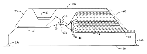
Figure 10 -- Preferred Embodiment
The preferred embodiment consists of the continuous triangular sorting pattern
of Figures
11A-11J and 12A-12G, implemented in a switching yard similar to that shown in
Figure 10.
The design of the yard shown in Figure 10 promotes maximum flexibility. Trains
are
received, classified on and depart from the same set of classification tracks
55, any of which are
long enough to hold an entire train. Tracks 55 are the same tracks shown as
tracks 1-9 in
Figures 1 lA-11J and 12A-12G and in the other drawing figures which depict car
movement
patterns. A raised hump 90 provides means for accelerating individual railcars
or groups of
railcars through sorting switches 115 into the classification tracks 55
allowing cars to be sorted
among all tracks which are accessible from that hump.
The design minimizes interference with hump 90 processing to maximize the
effective
sorting capacity of the facility. Means are provided in operative relationship
with classification
tracks 55 and with the mainline 30, for enabling departure of outbound trains
directly from
classification tracks 55 and for enabling arriving trains to be received into
the same tracks 55 for
storage while awaiting processing. Specifically, using wye track 35b, trains
for either direction
can move directly between the mainline 30 and classification tracks 55 using a
second set of
switches 80 at the Arrival/Deparlure end of the yard, without interfering with
hump 90
operations. Alternatively, trains can arrive or depart from "outside"
classification tracks 55 on
extreme left or right sides of the yard using "escape" tracks 10a or 10b,
while hump 90
operations continue simultaneously. While escape tracks are in use, this
prevents cars being
routed from the hump only into those extreme outside tracks which are blocked
(as shown in
Figure 19). Preblocked groups of cars making direct connections from inbound
to outbound
18
CA 02429520 2003-05-20
WO 02/42141 PCT/USO1/43075
trains can also be flat-switched using switches 80 at the Arrival/ Departure
end without
interfering with hump processing. A third, but undesirable alternative would
be for trains to
arrive and depart via the hump 90 itself and the hump switching lead track 40.
Since locomotives are very expensive assets, it is desirable to release them
from inbound
trains promptly, so locomotives can move quickly either to connecting outbound
trains or to the
locomotive servicing facility 20. Locomotives can move between their trains on
classification
tracks 55 and the locomotive servicing facility 20 using the yard running
track 25 via switches
80 at the Arrival/Departure end without interfering with hump processing, or
via the escape
tracks 10 causing only a very short interference to hump processing.
To process an arriving train, cars must be pulled back from the classification
tracks 55
onto one of the hump lead tracks 40. Arriving trains can also be received
directly on either of the
double hump lead tracks 40 for immediate processing. When retrieving railcars
from a
classification track 55 for second stage processing, this again may be
accomplished using escape
tracks 10 without preventing simultaneous hump processing of another train. To
maximize use
of escape tracks, inbound trains should be received on the outside of tracks
55 and first stage
sorting also performed onto these outside tracks. Second stage sorting, which
assembles
outbound trains for departure, should favor the middle of tracks 55 which are
not accessible
from the escape tracks. This block placement strategy permits any outside
track to be pulled
back to the hump via an escape track 10 while second stage sorting proceeds
concurrently.
For sorting of railcars, once a train has been positioned on the hump
switching lead 40, a
locomotive or car pusher device may be used to slowly shove cars towards the
hump 90, where
cars are uncoupled and allowed to individually roll by gravity into their
proper classification
tracks 55. Then, conventional car retarder units may be used to control and
reduce their speed to
a safe velocity for impacting and coupling to other railcars already standing
on those tracks, or to
prevent cars from rolling out the far ends of the tracks.
As shown in Figure 22, "Dowty" units 120 are placed between the rails 125 of
each
classification track 55 where the flanges of car wheels can contact them.
Through this contact a
retarding force can be applied to the wheels. These hydraulic retarder units
may be spaced every
several yards for the entire length of the classification track. The "Dowty"
retarder system is
described in U.S. Patent 5,092,248 to Parry (1992) and its practical use and
application in prior
art citations Melhuish (1983) and Bick (1984). Many different kinds of
retarder units are
described in Class 104 Subclass 26.2. "Dowty" retarder units, proposed for the
preferred
embodiment are not separately shown in any of the drawing figures, since these
units are
distributed throughout the entire length of each classification track 55.
Alternative embodiments
might use conventional clasp retarders as described in U.S. Patent 5,388,525
to Bodkin (1993),
"Screw" type retarders as in U.S. Patent 4,480,723 to Ingvast (1984), or
magnetic induction
retarders as in U.S. Patent 5,676,337 to Giras (1997), or other means of car
retardation.
Car pushers consist of mechanical arms, levers or other devices which can
accelerate or
propel cars without using a switching locomotive. Davis (1967) proposed the
use of mechanical
19
CA 02429520 2003-05-20
WO 02/42141 PCT/USO1/43075
car pushers in his Master's thesis on folded two stage yards, but use of such
devices in hump
yard operations has not yet proven practical. Such devices are widely utilized
in other kinds of
industrial applications such as coal train unloading facilities, and are
categorized under Class 104
Subclass 176. Some U.S. Patents describing such devices include 4,354,792 to
Cornish (1982)
and 4,926,755 to Seiford (1990). However in the preferred embodiment, it is
envisioned that
hump processing will be performed by entirely conventional means utilizing
conventional
switching locomotives.
Conventional track switches 115 connect the hump lead 40 into the
classification tracks
55 and are used to control routings of individual railcars. Class 104 Subclass
130.01 is devoted
to these devices. Since the problems of switching railroad cars were solved
many years ago,
most recent patents in this class are devoted to monorails and industrial
vehicle switching. Some
U.S. Patents relating to railroad track switches include 1,825,415 to
Overmiller (1931) and
4,174,820 to Kempa (1979).
During second stage sorting, cars are humped exclusively into a very limited
number of
tracks 55 representing only the specific trains) currently being closed out.
Other tracks never
receive any cars during this second stage sort, so mechanical forces may
safely conduct
inspections and repair cars on those tracks during second stage sorting
operations. Because
mechanical inspection and repairs can be performed practically anytime,
arriving trains can be
humped immediately upon arrival (as soon as air brakes can be' bled off)
without needing to wait
for complete inspection of the inbound cars. Cars can be inspected anytime
before the final
second stage sort.
To facilitate access by maintenance personnel, cart roads or paths 60 are
provided
between every set of classification tracks 55. This speeds the bleeding of air
brakes and car
inspection, and since carts can bring needed tools and materials directly to
the location of the car,
it maximizes the likelihood that mechanical defects can be repaired without
having to shop the
car. Cars having serious defects can still be removed from the outbound train
in the second stage
sort. These same cart roads faciliate easy access for engineering forces to
maintain power
switches and retarder systems in the yard. Cart roads are included in all
drawing figures for the
proposed facility designs.
Davis (1967, pg 61) suggested that icing, cleaning and minor repair might be
accomplished in the classification yard through provision of cart paths, but
on pages 80-81 he
insisted that inspection must still be accomplished before the first sorting.
By contrast, in
accordance with this invention, even inspection can be performed in the
classification yard.
Because of the second chance afforded by multiple stage switching techniques
to separate any
bad-order cars that cannot be repaired in the classification yard, it is
unnecessary to delay hump
processing of inbound trains for inspection. That will offer a considerable
advantage since
connections potentially as tight as one hour could be made using the proposed
new method of
operation, whereas complete inspection of an entire inbound train may often
require several
hours at least. Currently, cars arriving on late inbound trains will miss
their connections
CA 02429520 2003-05-20
WO 02/42141 PCT/USO1/43075
awaiting inspection of other cars on the same train, which cars don't all
necessarily have tight
connections. By processing each inbound train immediately upon arnval, those
tight connections
could still be protected and only those individual cars having tight
connections would have to be
inspected and repaired right away. Prior literature, including Davis (1967)
actually teaches
against the practice of inspection and repair in the classification tracks
which is advocated by this
invention.
Yard designs proposed here offer a distinct advantage over prior art two-stage
yard
designs shown in Figures 17, 18 and 20. In accordance with this invention,
inbound train
receiving, departure, first stage and second stage sorting operations are all
conducted on the
same set of tracks -- so whenever any outbound train has too many cars, it is
easy to divert
excess cars back to the proper first stage classification track 55 designated
for a latex departing
train. If that particular first stage classification track is unavailable
because it has been turned
over to mechanical personnel, the excess cars can be temporarily diverted to a
different track, and
moved back to the correct track later.
In prior art multiple stage yard designs, since first and second stage
classification tracks
are in separate sub-yards, it is hard to get excess cars back to their
appropriate first stage tracks
for a latex-departing train. For perhaps this reason, along with the
requirement that all tracks be
completely cleared after each group of trains has been assembled (using the
prior art multiple
stage batch methods), no prior art reference addresses the question of how
priority based sorting
to specific trains might be accomplished using multiple stage switching
methods.
Likewise, no known prior art addresses the opportunity to completely eliminate
the flat
switching "trim" operation now needed for final train assembly. Although Davis
(1967, pg. 59)
alludes to a theoretical possibility of building a complete train on a single
track, this is
contradicted by Davis' Figure 4-6 on page 58 where he shows a train being
"doubled" for final
train assembly. Although prior art does suggests a means of reducing outbound
train assembly
time, it stops short of suggesting and fails to reduce to practice any means
of totally eliminating
the need for flat switching for outbound train assembly.
Troup (1975) on page 7 Figure 2 shows a yard design having arrival, receiving
and
classification performed in the same set of tracks. On the same page it is
explained this is a "flat"
yard design. In prior art hump yard designs combined receiving and departure
yards are not
unusual, and occasionally classification tracks are extended to also serve as
departure tracks. But
the combination of all three functions of arrival, classification and
departure into a single set of
tracks as proposed by this invention, is not known in any prior art hump yard
design.
Herringbone tracks provide a means for reducing rather than eliminating train
assembly
time. For example in Figure 7, since three is the largest number of pockets
with car stopper
devices 65 provided on any individual hernngbone track; any train of more than
three blocks
will need to pick up cars from an additional track. With the increasing number
of blocks carried
by typical trains today, it is likely that a flat switching operation would
still be required for final
train assembly even using a herringbone track arrangement. By contrast, not
only do multiple
21
CA 02429520 2003-05-20
WO 02/42141 PCT/USO1/43075
stage switching methods impose no predetermined upper limits on the maximum
number of
blocks any train may carry, but the yard facilities needed are much less
expensive to construct
than herringbone tracks.
Undoubtedly, one reason why prior art stopped short of suggesting outbound
trains
could be built "complete" on a single track, as this invention does, are
difficulties of maintaining
accurate car speed control over such long distances. Conventional "clasp"
retarder systems as
described in U.S. Patent 5,388,525 to Bodkin (1993) apply speed control at
only a few points in
the yard. With increasing length of the classification tracks, variability in
railcar coefficients of
friction, or "rollability" makes it difficult to predict the speed at which
cars should be released
from the retarders so they will couple at a safe speed to cars already on the
track. Typically,
either too much retardation is applied causing cars to stop short of their
destinations, or not
enough retardation, allowing cars to crash into standing cars at an excessive
rate of speed or run
out the far ends of the tracks.
Given typical train lengths operated now of 8,000- 10,000 feet, it was
apparently not
deemed feasible to assemble such long trains on a single classification track
55 using car retarder
systems available in the 1960's when many of these prior art citations were
being developed. At
that time, the "Dowty" retarder system was still in the experimental stages in
Britain and its
capabilities were not yet proven, known or understood, so the prior authors
chose not to further
pursue this line of investigation. However, it has since been established that
"Dowty" retarder
system are in fact capable of maintaining continuous car speed control
throughout the very long
classification tracks proposed by this invention. Now a realistic means of
completely eliminating
the costly flat switching operation at the "trim" end of the yard can be
seriously suggested for the
first time.
Operation of the Preferred Embodiment
Prior art suggests that multiple stage sorting can only be used to build
"batches" of trains,
which must all depart close to the same time. The entire set of tracks must be
cleared out and
sorting Starts over with a new batch of trains. This leads to excessive
peaking of demands on
terminal resources -- it is more efficient to receive, process and dispatch
trains on a continuous,
steady-state basis. Continuous sorting improves the utility and practicality
of multiple stage
sorting methods.
Any "batch" multiple stage sorting method can be transformed into a continuous
process
by following two steps:
(a) "Replicate" the same block to track assignment pattern for each train,
although patterns
used for individual trains may be perturbed by skipping block positions as in
Figure 9.
(b) "Offset" the starting track assignment for each subsequent train by a
certain number of
tracks, usually I or 2 tracks for each new train. For example, blocks for
Train A might be
assigned to tracks 1 through 3; Train B to tracks 2 through 4, and train C to
tracks 3 through 5.
22
CA 02429520 2003-05-20
WO 02/42141 PCT/USO1/43075
The number of tracks required for each train depends on the number of blocks
in that
train, and the sorting pattern used. For example, to build a six block train
using a triangular
sorting pattern requires three tracks. To build a six block train using an
arithmetic sorting pattern
requires six tracks. "Overlap" measures the degree of interdependency between
multiple train
assignments using the same tracks. "Offset" and "Overlap" are related through
the following
mathematical expression:
Overlap = Number of Tracks required for each train - Offset
If three tracks are required for each train, then by offsetting assignments by
one track,
each train's block to track assignments will overlap by two tracks. If two
trains share all the
same tracks (zero offset), both trains are assembled simultaneously, but the
sorting process is
not continuously sustainable. With offset greater than or equal to the number
of tracks needed by
each train, block to track assignments do not overlap at all. Then only one
train at a time would
be built, and although the process is continuously sustainable, such non-
overlapping
assignments do not make the most effective use of available track space.
Normally, block to
track assignments should be offset by at least one track, but should also
overlap as well. By
both overlapping and offsetting block to track assignments the sorting process
can be sustained
indefinitely by starting a new train whenever a classification track becomes
available. In contrast
to prior art "batch" sorting methods, this method for continuous sorting
imposes no restriction
on the maximum number of blocks any particular train may carry. It utilizes a
different pattern of
block to track assignments than any prior art sorting process -- and produces
a novel result,
which is the continuous nature of the sorting process.
Figures 12A thru l~,G give a sequence of car movements based on the triangular
sorting
pattern, leading to a continuous sorting process. In these figures, both
initial and secondary
sorting are performed from the right, and trains depart towards the left.
Since each train has six
blocks, and the triangular pattern for a six block train requires three
tracks, then offsetting block
to track assignments by one track for each new train results in a two track
overlap. Train A can
be readied for departure by rehumping tracks #1, #~ and #3. This not only
arranges all blocks
for train A on track #l, but also begins assembly of trains B and C on tracks
#2 and #3,
respectively. From this point (Figure 12D), one outbound train is completed
for every additional
track reprocessed, while the next two trains are "in process" of construction
at all times. More
trains could be added to extend the sequence at any time before train A is
completed. By starting
new trains whenever classification tracks become available, the sorting
process can be continued
indefinitely.
Although building several trains at once improves efficiency, it may imply a
loss of
flexibility. When block to track assignments for two trains overlap, the first
train cannot be
assembled without also at least partially starting construction of the second
train. Unfortunately
once second stage sorting has begun, if blocks become "buried" behind any
other blocks, cars
23
CA 02429520 2003-05-20
WO 02/42141 PCT/USO1/43075
may no longer be added to those blocks in any straightforward manner. For
example in figure
11C, track 3 contains the sequence (A4 B1 B3 B5) (A5) (A6). Although new cars
may still be
added to (A6), blocks B l, B3 and B5 appear to be closed out, so cars may no
longer be added
without a special switching move. Curiously however, after track 3 is
reprocessed in Figure
11D, these blocks move to "first out" position on tracks 3, 4 and 5
respectively, so they open up
again to receive additional cars. This shows that determination whether or not
a block is really
"closed out" may be a complex matter which depends not only on the current
block to track
configuration, but also planned future arrangements. In this instance cars for
blocks B 1, B3 and
B5 may be intermixed with the A6 cars without adverse effect, giving as an
allowable
configuration: (A4 B 1 B3 B5) (A5) (A6 B 1 B3 B5), so B 1, B3 and B5 are not
in fact closed out.
To summarize, if cars remain to be added to any blocks which would be closed
out by
reprocessing a track, then either second stage sorting must be postponed long
enough to add
those inbound cars first (possibly delaying departure of the first train), or
connections for the
second train may be missed. Reducing overlap in block to track assignments
reduces
interdependency between subsequent train departures, but also utilizes track
space less
intensively, and so requires more tracks in the yard.
This problem can be managed by overlapping block to track assignments for
outbound
trains according to the planned order of departure. The proper amount of
overlap depends on
how closely train departures are scheduled. For departures scheduled less than
an hour apart, the
prior art triangular pattern might be used to assemble both trains
simultaneously. For departures
two or three hours apart, a one or two track overlap as in Figures 11A-113 or
12A-12G,
respectively, should be used. Tables 11 and 12 describe the sequence of
railcar movements
shown in drawing figures 1 lA-11J and 12A-12G, respectively. For departure
spaced wider than
this, separate tracks should be used for each train (no overlap) so each train
may be assembled
independently.
If any classification track will be required to hold too many cars during an
intermediate
sorting stage, it may be possible to prevent this overflow by either reducing
the overlap between
subsequent trains, or by perturbing the sorting pattern to reduce the
utilization of that track, for
example by skipping an intermediate block position as in Figures 9A thru 9D.
Designs for the
preferred and additional embodiments in Figures 10, 13, 14 and 15 are
optimized for continuous
triangular or geometric sorting, since the length of the switching lead 40,
40a, or 40b
approximately equals the length of each yard track 55.
In this two stage sorting process, specific caxs can be selected for each
outbound train
based on car priority or delivery commitment. There are two different methods
of accomplishing
this:
(a) If classification tracks 55 are available, low priority cars in excess of
outbound train
capacity can be diverted from their primary classification in the first stage
sort, as may now be
done using a single stage sorting approach. This saves one handling for each
car diverted, but
24
CA 02429520 2003-05-20
WO 02/42141 PCT/USO1/43075
First Stage Setup A1,A3,A5 to Track 1
shown in Figure
11A A2,A6 to Track 2
A4,B1,B3,B5 to Track 3
B2,B6 to Track 4
B4,Ci,C3,C5 to Track 5
C2,C6 to Track 6
C4,D1,D3,D5 to Track 7
D2,D6 to Track 8
D4 to Track 9
Pull Back Track 1 A1 to Track 1
from the right
side, and reclassify A3 to Track 2
as follows.
Outcome shown in FigureA5 to Track 3
11B.
Pull Back Track 2 A2,A3 to Track 1
from the right
side, and reclassify A6 to Track 3
as follows.
Outcome shown in Figure
11C.
PuII Back Track 3 A4,A5,A6 to Track 1 (Train A is completed)
from the right
side, and reclassify B1 to Track 3
as follows.
Outcome shown in FigureB3 to Track 4
11D.
B5 to Track 5
Pull Back Track 4 B2,B3 to Track 3
from the right
side, and reclassify B6 to to Track 5
as follows.
Outcome shown in Figure
11E.
Pull Back Track S B4,B5,B6 to Track 3 (Train B is completed)
from the right
side, and reclassify C1 to Track 5
as follows.
Outcome shown in FigureC3 to Track 6
11F.
C5 to Track 7
Pull Back Track 6 C2,C3 to Track 5
from the right
side, and reclassify C6 to to Track 7
as follows.
Outcome shown in Figure
11G
Pull Back Track 7 C4,C5,C6 to Track 5 (Train C is completed)
from the right
side, and reclassify Dl to Track 7
as follows.
Outcome shown in FigureD3 to Track 8
11H.
D5 to Track 9
Pull Back Track 8 D2,D3 to Track 7
from the right
side, and reclassify D6 to to Track 9
as follows.
Outcome shown in Figure
11I.
Pull Back Track 9 D4,D5,D6 to Track 7 (Train D is completed)
from the right
side, and reclassify
as follows.
Outcome shown in Figure
11J. All
four trains are ready
for departure
towards the left.
Table 11
CA 02429520 2003-05-20
WO 02/42141 PCT/USO1/43075
First Stage Setup Al,A3,A5 to Track 1
shown in
Figure 12A A2,A6,B1,B3,B5 to Track 2
A4,B2,B6,C1,C3,C5 to Track 3
B4,C2,C6,D1,D3,D5 to Track 4
C4,D2,D6 to Track 5
D4 to Track 6
PuII Back Track I Al to Track I
from the right
side, and reclassify A3 to Track 2
as follows.
Outcome shown in FigureAS to Track 3
12B.
Pull Back Track 2 AZ,A3 to Track I
from the right
side, and reclassify BI to Track 2
as follows.
Outcome shown in FigureA6,B3 to Track 3
I2C.
BS to Track 4
Pull Back Track 3 A4,AS,A6 to Track 1 (Train A is completed)
from the right
side, and reclassify B2,B3 to Track 2
as follows.
Outcome shown in FigureC1 to Traclc 3
12D.
B6,C3 to Track 4
CS to Track 5
Pull Back Track 4 B4,BS,B6 to Track 2 (Train B is completed)
from the right
side, and reclassify C2,C3 to Track 3
as follows.
Outcome shown in FigureD1 to Track 4
12E.
C6,D3 to Track 5
DS to Track 6
Pull Back Track 5 C4,CS,C6 to Track 3 (Train C is completed)
from the right
side, and reclassify D2,D3 to Track 4
as follows.
Outcome shown in FigureD6 to Track 6
12F.
Pull Back Track 6 D4,DS,D6 to Track 4 (Train D is completed)
from the right
side, and reclassify
as follows.
Outcome shown in Figure
12G.
All four trains are
ready for
departure towards
the left.
Table 12
requires a decision very early on outbound train make up. It also requires
that a separate
classification track 55 be available to receive the cars, implying that two
different outbound
trains must be built simultaneously carrying the same blocks.
(b) Diverting cars into a rehump track generally does not make sense in
multiple stage
sorting. Instead, it is better to just ignore the outbound train in the first
stage sort and keep all
26
CA 02429520 2003-05-20
WO 02/42141 PCT/USO1/43075
cars intermixed until the second stage sort. Excess cars can easily be
"rolled" to a later train in the
second stage sort. This preserves the rnaxirnum degree of operating
flexibility, and avoids the
need to build more than one train at a time for each block.
The ability to intermix cars for different trains, and thereby defer decision
making on the
exact makeup of each outbound train until the second stage sort is a key
benefit of the multiple
stage switching process. The method is robust even if train schedules cannot
be strictly adhered
to, and emergency train schedule changes are well tolerated. Once assembled,
outbound trains
may simply rest on classification tracks 55 until operational circumstances
permit their departure.
Provided a sufficient number of tracks 55 remain available for continued
operation of the
facility, holding trains as needed in the yard does not prevent or interfere
with the makeup of any
other trains.
Figs 13, 14 and 15 -- Additional Embodiments
Variations on this theme include a lower-cost stub end, and higher-capacity
double ended
design shown in Figures 13 and 14. In each of these designs, all trains must
arrive and depart
through escape tracks 10 or over the hump 90. If only a locomotive uses the
escape track, the
interruption only lasts for a couple of minutes; but arrival or departure of a
train might require
20-30 minutes. This interference might be tolerated if trains are permitted to
arrive or depart only
during second stage sorting, when switching activities are limited only to a
few tracks, which are
hopefully all concentrated on the opposite side of the yard. But this required
use of escape tracks
and the required coordination in a stub end yard would inevitably lead to
delays in hump
processing, receiving or departing trains, or both.
A "lapped" variation of the high capacity double-ended yard is shown in Figure
15. This
configuration overcomes the disadvantage of escape tracks by providing a
second set of switches
opposite each hump with dedicated arrival/departure leads in both directions.
Switches 100 at
the Westbound Departure/Eastbound Arrival end are provided opposite to hump
90b; and
switches 110 at the Eastbound Departure/Westbound Arrival end are provided
opposite to hump
90a. These second sets of switches 100 and 110 in Figure 15 serve the same
purpose as do
switches 80 at the Arrival/Departure end in Figure 10; which provide a means
for direct arrival
and departure of trains from and to the mainline 30 without interfering with
hump 90 processing
activities. Tracks connected to switches 100 and 110 on the outside of the
yard are used for
receiving and assembling outbound trains, while tracks 105 in the middle are
mostly used for
first stage sorting. This leads to a "cross flow" traffic pattern within the
yard, whereby
eastbound trains are received via the eastbound receiving/westbound departure
switches 100;
cars are humped into one of the middle tracks 105 in the first stage sort; and
finally outbound
eastbound trains are assembled (using the opposite hump) and depart using the
westbound
receiving) eastbound departure switches 110. Westbound cars progress through
the yard in the
opposite direction.
27
CA 02429520 2003-05-20
WO 02/42141 PCT/USO1/43075
Operation of the Additional Embodiments
First stage sorting from one end of the yard and secondary sorting from the
other hump
eliminates the need to switch cars into the same track from both ends of the
yard at the same
time, since the same track will never be used for both purposes at the same
time. If secondary
sorting is done from the opposite end of the yard, the train must be set up
"backwards" by
inverting the sequence of block subscripts in the first stage sort, as shown
in Figures 16A thru
16G. Table 16 below describes the sequence of railcar movements shown in
drawing figures
16A-16G. An interlocked control system should be provided to ensure that only
one hump has
"control" over each track at any time, and also to provide lock-out or "blue
flag" protection, by
First Stage Setup A6,A4,A2 to Track 1
shown in Figure
16A AS,A1,B6,B4,B2 to Track 2
A3,BS,B1,C6,C4,C2 to Track 3
B3,CS,C1,D6,D4,D2 to Track 4
C3,DS,D1 to Track 5
D3 to Track 6
Pull Back Track 1 A6 to Track 1
from the left side,
and reclassify as A4 to Track 2
follows. Outcome
shown in Figure 16B. A2 to Track 3
Pull Back Track 2 A4,A5 to Track 1
from the left side,
and reclassify as B6 to Track 2
follows. Outcome
shown in Figure 16C. A1,B4 to Track 3
B2 to Track 4
Pull Back Track 3 A1,A2,A3 to Track 1 (Train A is completed)
from the left side,
and reclassify as B4,B5 to Track 2
follows. Outcome
shown in Figure 16D. C6 to Track 3
B1,C4 to Track 4
C2 to Track 5
Pull Back Track 4 B1,B2,B3 to Track 2 (Train B is completed)
from the left side,
and reclassify as C4,C5 to Track 3
follows. Outcome
shown in Figure 16E. D6 to Track 4
C1,D4 to Track 5
D2 to Track 6
Pull Back Track 5 C1,C2,C3 to Track 3 (Train C is completed)
from the left side,
and reclassify as D4,D5 to Track 4
follows. Outcome
shown in Figure 16F. Dl to Track 6
Pull Back Track 6 D1,D2,D3 to Track 4 (Train D is completed)
from the left side,
and reclassify as
follows. Outcome
shown in Figure 16H.
All four trains
are ready for departure
towards the
left.
Table 16
28
CA 02429520 2003-05-20
WO 02/42141 PCT/USO1/43075
preventing cars from being routed into tracks where mechanical personnel are
inspecting or
repairing equipment. Although the double ended design increases capacity,
sorting activity may
become so intense that it becomes difficult for mechanical personnel to find
the time necessary to
inspect and maintain equipment without increasing the amount of time cars must
remain in the
yard.
For the lapped design shown in Figure 15, while the hump at one end of the
yard is
engaged in primary sorting -- sending cars to tracks in the middle of the yard
--the opposite
hump should be assembling trains by secondary sorting into the outer tracks.
Center tracks can
receive cars from humps at either end of the yard, but not at the same time
(unless the car retarder
or speed control systems are specifically designed to allow this.)
Figures 17 thru 20 -- Alternative Emhodiments
Figures 17, 18 and 20 show prior art yard designs (Chnstianson, 1972) for the
two stage
arithmetic pattern, or "Sorting by Block" as described in Figures 8A thru 8E.
Figures 17 and 18
show "folded" yard designs which use a back-and-forth car movement pattern,
whereas Figure
20 shows an "in line" version of a two-stage sorting yard. These designs are
more complex and
less flexible than simple triangular sorting yards, and the sorting by block
process does not
permit car inspection or repairs to be performed in the first stage
classification yard.
The most critical shortcoming of the "folded" design is the bottleneck which
occurs
between the two sections of the yard, and through which every car must move
twice. Davis
( 1967) suggested this be overcome by using mechanical devices rather than
gravity to accelerate
and decelerate cars at a high speed through this zone. Dual humps (Figure 19)
could also be
provided to increase capacity, but if both humps operate simultaneously,
access to half the tracks
in each yard are blocked by trains being humped in the opposite direction.
The "in line" design of Figure 20 eliminates this bottleneck, but reinstitutes
the need for
an independent receiving yard, geographically widely separated from the
departure yard, making
flat switching or "block swapping" difficult and inconvenient.
Operation of the Alternative Embodiments
The arithmetic or "sorting by block" method can also be continuously sustained
by
offsetting and overlapping block to track assignments. Figures 8A thru 8E show
the prior art
method of "sorting by block." In this method, cars for the first block on each
train are
intermixed on the first track, cars for the second block are intermixed on the
second track, and so
on. Table 8 below describes the sequence of railcar movements shown in drawing
figures 8A-
8E.
For continuous sorting, the first block of the second train is placed on the
second track
(instead of the first track), the first block of the third train is placed on
the third track (instead of
the first track), and so on. Figures 21A thru 21I show the process of building
a six-block train
using continuous arithmetic sorting. Table 21 describes the sequence of
railcar movements
29
CA 02429520 2003-05-20
WO 02/42141 PCT/USO1/43075
First Stage Setup A4,B4,C4,D4 to Track 1
shown in
Figure 8A A3,B3,C3,D3 to Track 2
A2,B2,B2,D2 to Track 3
A1,B1,C1,D1 to Track 4
Pull Back Track 4 AI to Track 4
from the right
side, and reclassifyB I to Track 5
as follows.
Outcome shown in CI to Track 6
Figure 8B.
Dl to Track 7
Pull Back Track 3 A2 to Track 4
from the right
side, and reclassifyB2 to Track 5
as follows.
Outcome shown in C2 to Track 6
Figure 8C.
D2 to Track 7
Pull Back Track 2 A3 to Track 4
from the right
side, and reclassifyB3 to Track 5
as follows.
Outcome shown in C3 to Track 6
Figure 8D.
C3 to Track 7
Pull Back Track I A4 to Track 4
from the right
side, and reclassifyB4 to Track 5
as follows.
Outcome shown in C4 to Track 6
Figure 8E.
All four trains are C4 to Track 7
ready for
departure towards
the left.
Table ~
Prior Art
shown in drawing figures 21A-ZlI. This requires reprocessing six tracks to
complete
construction of the first train, which also starts assembly of five other
trains. This excessive
interdependency between multiple trains is a major weakness of the arithmetic
sorting method.
Because of this high degree of overlap, the continuous "sorting by block"
pattern seems best
suited for assembling trains containing no more than three or four blocks at
most; or for very
high volume facilities which depart trains on very regular, frequent
intervals. By contrast,
triangular sorting can build a six block train having overlapping assignment
with no more than
one or two other trains.
In general, triangular sorting yards appear to be less expensive to construct,
and simpler
and more flexible in operation than "folded" arithmetic yard designs. Having
less overlap
between trains, and by offering more flexibility than arithmetic sorting, the
"preferred
embodiment" of Figure 10 based on triangular sorting appears to be the
superior design for
common applications.
CA 02429520 2003-05-20
WO 02/42141 PCT/USO1/43075
First Stage Setup A1 to Track 1
shown in Figure
ZIA A2,B1 to Track 2
A3,B2,C1 to Track 3
A4,B3,C2,D1 to Track 4
AS,B4,C3,D2 to Track 5
A6,BS,C4,D3 to Track 6
B6,CS,D4 to Track 7
C6,D5 to Track 8
D6 to Track 9
Pull Back Track 2 A2 to Track 1
from the right
side, and reclassify B1 to Track 2
as follows.
Outcome shown in Figure
21B.
Pull Back Track 3 A3 to Track 1
from the right
side, and reclassify B2 to Track 2
as follows.
Outcome shown in FigureC1 to Track 3
21C.
Pull Back Track 4 A4 to Track 1
from the right
side, and reclassify B3 to Track 2
as follows.
Outcome shown in FigureC2 to Track 3
21D.
Dl to Track 4
Pull Back Track 5 AS to Track 1
from the right
side, and reclassify B4 to Track 2
as follows.
Outcome shown in FigureC3 to Track 3
21E.
D2 to Track 4
Pull Back Track 6 A6 to Track 1 (Train A is completed)
from the right
side, and reclassify BS to Track 2
as follows.
Outcome shown in FigureC4 to Track 3
21F.
D3 to Track 4
Pull Back Track 7 B6 to Track 2 (Train B is completed)
from the right
side, and reclassify CS to Track 3
as follows.
Outcome shown in FigureD4 to Track 4
21G
Pull Back Track 8 C6 to Track 3 (Train C is completed)
from the right
side, and reclassify DS to Track 4
as follows.
Outcome shown in Figure
21H.
Pull Back Track 9 D6 to Track 4 (Train D is completed)
from the right
side, and reclassify
as follows.
Outcome shown in Figure
21I. All
four trains are ready
for departure
towards the left.
Table 21
31
CA 02429520 2003-05-20
WO 02/42141 PCT/USO1/43075
Accordingly, the reader will see that the multiple stage railcar sorting
methods presented
here may be used to select particular railcars on a priority basis, for
departure on specific
outbound trains as well as offering numerous other advantages. New yard
designs needed to
optimize application of the methods have also been presented. These same
methods may also be
implemented in conventional yards with some loss of efficiency. Given the
mufti billion dollar
investment the rail industry has made in prior art, single stage sorting yards
-- and the enormous
time and expense required to replace all of them -- serious consideration
should be given either to
implementation of these multiple stage methods, or further development and
refinement of single
stage priority sorting methods, in existing facilities.
Alternatively, new multiple stage sorting yards may be built at a few
strategic locations,
to establish a guaranteed delivery time train service network for single car
rail shipments. Either
approach would permit implementation of freight railroad revenue management,
to provide an
effective means of establishing guaranteed delivery appointments for every
railcar.
These multiple stage sorting methods have many advantages, some previously
refered to:
(a) By allowing for inspection and repair of cars during otherwise idle time
spent in the
classification yard, the total amount of time required to pass through the
yard can be reduced.
(b) By offsetting and overlapping track assignment patterns for subsequent
trains, the
multiple stage sorting process can be sustained on a continuous basis.
(c) If the number of cars available exceeds the capacity of the train, the
decision on exact
train makeup can be deferred until the train is assembled, immediately before
train departure
rather than requiring such decisions 12,-24 hours in advance.
(d) The bottleneck flat switching operation at the "trim" end of the yard is
completely
eliminated.
(e) A variety of yard configuration options have been presented allowing
facilities to be sized
appropriately to their intended workloads. Small hump yards can be
economically constructed to
replace obsolete flat switching facilities, allowing more direct "point to
point" operations and
reducing the number of required intermediate terminal handlings.
(f) The yard designs proposed here have the capacity of a traditional hump
yard facility
while maintaining the flexibility associated with traditional flat yard
design.
Although the description above contains many specificities, these should not
be
construed as limiting the scope of the invention, but as merely providing
illustrations of some of
the presently preferred embodiments of the invention. For example, these
methods can be
accomplished in conventional railyard designs, so the scope of the process
claims is not limited
to the physical railyard designs presented here. Those rail yard designs
improve the efficiency of
the multiple stage sorting methods and highlight some of the deficiencies of
current yard designs,
as well as demonstrate reduction to practice of the new sorting methods.
Thus the scope of the invention should be determined by the appended claims
and their
legal equivalents, rather than by the examples given.
32