Note: Descriptions are shown in the official language in which they were submitted.
CA 02429538 2003-05-20
WO 02/062675 PCT/USO1/43328
-1-
TAMPER-EVIDENT DISPENSING CLOSURE WITH
PARTIAL BREAKAWAY COVER
TECHNICAL FIELD
The invention relates to closure structures. Particularly, the invention
relates to a closure structure that has a closure body defining a dispensing
orifice, and an associated hinged lid. The invention particularly relates to
such closure structures wherein a tamper-evident feature is associated with
the closure body and the lid, the tamper-evident feature preventing opening
of the lid unless the tamper-evident feature is torn or otherwise broken.
BACKGROUND OF THE INVENTION
AND
TECHNICAL PROBLEMS POSED BY THE PRIOR ART
A variety of container closures have been developed or proposed
wherein an initial opening of a lid or a dispensing spout structure provides
visual evidence of such an occurrence-even after the lid or spout has been
subsequently closed.
Some types of tamper-evident systems require an overt action by the
user such as removing an added component such as a removable "neck band"
or the like. Other tamper-evident systems require removing or breaking an
integral element' such as a "tear away" feature to permit removal of the
closure or to otherwise open the container. Some examples of such systems
are represented by U.S. Patent Nos. 4,487,324; 5,058,775; 5,201,440;
5,427,260; and 5,875,907.
Other types of tamper-evident systems are more automatic in their
function. As the user opens the package, such as by removing the closure
from the container, an integral component of the closure is irreparably
broken in such a way that it is evident the original seal has been breached.
Some examples of such systems are represented by U.S. Patent Nos.
4,196,818; 4,153,174; and 5,875,906.
CA 02429538 2003-05-20
WO 02/062675 PCT/USO1/43328
-2-
While the above mentioned closures can function well for the
purposes for which they have been designed, the present inventors have
recognized that it would be desirable to provide an improved tamper-evident
closure which could be readily fabricated to associate with certain types of
lids or flow control elements and which, prior to initial opening, could
enhance the cosmetic appearance of the closure. The present inventors have
recognized that it would be desirable if such a tamper-evident closure could
be easily installed on a container to its tamper-indicating ready condition
for
eventual delivery to the consumer. The present inventors have recognized
that it would be desirable to provide a tamper-evident closure that was easy
and self explanatory to use by consumers while still providing an attractive
appearance, ease of application by packagers, and simplicity in molding by
the closure producer.
BRIEF SUMMARX OF THE INVENTION
The invention provides a closure structure having an appearance that
leads the user to attempt to open the container in the usual manner. In doing
so, however, a first tamper-evident element, a cover part, is automatically
removed from the closure structure. This exposes an indication that the
dispensing seal of the closure structure may have been opened and also
provides a convenient secondary means of opening a lid part for continuing
use of the package.
Furthermore, if the overall design of the package so dictates, or if the
user so elects, the entire closure structure may be removed from the
container before or after the first tamper-evident element is removed. In this
event, a second tamper-evident element is automatically separated from the
closure structure, and remains on the container, thereby revealing that the
closure/container interface has been breached.
The present invention provides a closure structure having a closure
body with a dispensing orifice, and a cap which is configured to overlie the
closure body. The cap includes a lid part and a cover part connected
CA 02429538 2003-05-20
WO 02/062675 PCT/USO1/43328
-3-
together by a frangible feature. The lid part is hinged to the closure body.
The lid and cover parts as a unit can be pivoted from an initially open, as-
molded, orientation to a position wherein the parts lock onto the closure
body. The frangible feature, and the locking of the parts onto the closure
body, constitute a tamper-evident feature which must be discernibly breached
to initially gain access to the dispensing orifice.
The frangible feature preferably comprises a line of weakness formed
through the material of the cap, such as formed by a through-cut or groove
made discontinuous by small, breakable bridging webs.
According to an exemplary embodiment, the closure body comprises a
flat end wall or deck and a depending annular body sidewall or body skirt.
An annular shoulder is formed above the sidewall. The lid part includes a
first partially circular top wall and a depending first partially annular lid
sidewall or lid skirt. The lid skirt includes an edge which fits on the
annular
shoulder when the lid part is closed onto the closure body. The lid skirt and
the closure body provide first and second latching mechanisms arranged on
opposing sides of the hinge respectively, around a circumference of the lid
part.
The cover part includes a second partially circular top wall and a
second partially annular skirt which substantially complete, with the first
partially circular top wall and the first partially annular skirt of the lid
part,
an overall circular top wall and an overall annular skirt of the cap. A third
latching mechanism is arranged between the cover part and the closure body
at a front side of the closure structure, opposite to the hinge.
Guard walls can be arranged on the annular shoulder, which form
partially annular channels for receiving edge portions of the lid skirt. The
guard walls prohibit the de-latching of the lid part by someone attempting to
separate the lid edge from the closure body using a predominantly radial
force.
CA 02429538 2003-05-20
WO 02/062675 PCT/USO1/43328
-4-
To open the closure structure for the first time, the cover part is pried
upwardly, causing the breaking of the line of weakness, and a separation of
the cover part from the lid part. Removal of the cover part exposes a front
wall of the lid part, and a lifting lip that extends forwardly from the front
wall. In order to open the lid part, the user then exerts an upwardly directed
force on the lifting lip to cause a progressive separation of the two latching
mechanisms and opening of the lid part.
An important advantage to the manufacturer of the inventive closure
structure is that molding thereof may be accomplished without any unusual
or complicated features in the injection mold used to form the structure. All
surfaces may be formed by standard "straight opening" molds. No
complicated side actions, etc., are required. The closure structure is cost
effectively manufactured.
Advantages of the inventive closure structure also accrue to the
packager and retailer. In handling of the parts during completion of the
closure preparation, subsequent bulk handling and shipment, and application
to containers, the absence of appendages or features that project beyond the
outside surfaces of the closure structure allow the parts to be easily and
efficiently handled throughout the distribution chain. Once on the container,
the closure structure presents a smooth, aesthetically pleasing appearance to
potential purchasers at point of sale.
The closure structure of the invention is simple and user friendly.
The initial opening movement is familiar to the user, and the opening
sequence is self explanatory.
Numerous other advantages and features of the present invention will
become readily apparent from the following detailed description of the
invention, from the claims, and from the accompanying drawings.
CA 02429538 2003-05-20
WO 02/062675 PCT/USO1/43328
-S-
BRIEF DESCRIPTION OF THE DRAWINGS
The accompanying drawings form part of the specification, and like
numerals are employed to designate like parts throughout the same.
FIG. 1 is a perspective view of a closure structure of the invention
mounted on a container neck (container neck shown in fragmentary fashion);
FIG. 2 is a plan view of the closure structure of FIG. 1;
FIG. 3 is a right side view of the closure structure of FIG. 1;
FIG. 4 is a front view of the closure structure of FIG. 1;
FIG. 5 is a sectional view taken generally along line 5-5 of FIGURE
2 of the closure structure as installed on a container neck;
FIG. 6 is a sectional view taken generally along line 6-6 of FIG. 2;
FIG. 7 is a perspective view of the closure structure of FIG.1, with a
tamper-evident feature removed;
FIG. 8 is a plan view of the closure structure of FIG. 7;
FIG. 9 is a right side view of the closure structure of FIG. 8;
FIG. 10 is a front view of the closure structure of FIG. 8;
FIG. 11 is a perspective view of the closure structure of FIG. 7 in an
open condition;
FIG. 12 is a plan view of the closure structure of FIG. 11;
FIG. 13 is a right side view of the closure structure of FIG. 11;
FIG. 14 is a front view of the closure structure of FIG. 11;
FIG. 15 is a sectional view taken generally along line 15-15 of FIG.
12;
FIG. 16 is a sectional view taken generally along line 16-16 of FIG.
12;
FIG. 17 is a top perspective view of an alternate embodiment closure
structure; and
FIG. 18 is a bottom perspective view of the alternate embodiment
closure structure of FIG. 17.
CA 02429538 2003-05-20
WO 02/062675 PCT/USO1/43328
-6-
DETAILED DESCRIPTION
While this invention is susceptible of embodiment in many different
forms, this specification and the accompanying drawings disclose only some
specific forms as examples of the invention. The invention is not intended to
be limited to the embodiments so described, however. The scope of the
invention is pointed out in the appended claims.
For ease of description, most of the figures illustrating the invention
show a dispensing system in the typical orientation that it would have at the
top of a container when the container is stored upright on its base, and terms
such as upper, lower, horizontal, etc., are used with reference to this
position.
It will be understood, however, that the dispensing system of this invention
may be manufactured, stored, transported, used, and sold in an orientation
other than the position described.
The dispensing system of this invention is suitable for use with a
variety of conventional or special containers having various designs, the
details of which, although not illustrated or described, would be apparent to
those having skill in the art and an understanding of such containers. The
container ep r se described herein forms no part of some embodiments and
concepts of the invention and therefore is not intended to limit the present
invention. It will also be understood by those of ordinary skill that novel
and
non-obvious inventive aspects are embodied in the described exemplary
closure structure alone.
An exemplary embodiment of a closure structure 30 according to the
invention is illustrated in FIGS. 1-16.
FIGURE 1 illustrates a closure structure 30 adapted to be installed on
a container neck 32. The closure structure 30 is adapted to be used with a
container having a mouth or other opening to provide access to the container
interior and to a product contained therein. The closure structure 30 could
be used to dispense many types of materials, including, but not limited to,
relatively low or high viscosity liquids, particulates, etc. as constituting a
CA 02429538 2003-05-20
WO 02/062675 PCT/USO1/43328
_7_
food product, a personal care product, an industrial or household cleaning
product, or other chemical compositions (e.g., compositions for use in
activities involving manufacturing, commercial or household maintenance,
construction, agriculture, etc.).
The container with which the closure structure may be used would
typically be a squeezable container having a flexible wall or walls which can
be grasped by the user and squeezed or compressed to increase the internal
pressure within the container so as to force the product out of the container
and through the closure structure 30. The container wall typically has
sufficient, inherent resiliency so that when the squeezing forces are removed,
the container wall returns to its normal, unstressed shape. Such a squeezable
wall container is preferred in many applications but may not be necessarily
preferred in other applications. For example, in some applications it may be
desirable to employ a generally rigid container or even a pressurized
container.
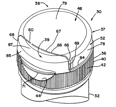
The closure structure 30 includes a closure body 36 substantially
covered by a cap 37. The body 36 includes an annular body sidewall or
body skirt 40 having on an exterior thereof knurling or ribs 42, and a
partially circular plain area 44. The cap 37 includes a substantially flat
circular end wall 48 and a depending annular cap skirt or cap sidewall 52.
The cap 37 includes a lid part 38 and a cover part 39.
The cap includes a perimeter line of weakness 60 formed by a
through-cut made discontinuous by intermittent webs or bridges 66, or by a
reduced material thickness or notch, or by perforations, or by another known
method. The line of weakness 60 has a top segment 67 that extends across
the end wall 48 and side segments 68, 69 that extend down the skirt 52 at
opposite ends of the top segment 67. The line of weakness defines the
intersection of the lid part 38 and the cover part 39.
The cover part 39 provides a lifting tab 71 on a front side thereof,
arranged in registry with the plain area 44, the plain area 44 providing a
CA 02429538 2003-05-20
WO 02/062675 PCT/USO1/43328
- $ _
convenient space into which a user can insert a finger to underlie the tab 71
for eXerting an upward lifting force.
FIGURES 2 through 16 illustrate further features of the closure
structure 30. The lid part 38 is attached to the body 36 via a hinge 76
(FIGURES 3, 5, 12, and 13). The hinge 76 is preferably a snap action
hinge. Such a hinge is disclosed in the U.S. patent No. 5,642,824, the
disclosure of which is incorporated herein by reference thereto. In an
alternate embodiment, the lid part 38 need not be connected with a snap-
action hinge. A floppy hinge may be used instead.
As shown in FIGURE 1, the lid part 38 includes a partially annular
lid sidewall or lid skirt 78 and a partially circular lid top wall 79. The lid
skirt 78 includes side recessed wall portions 82, ~84 (FIGURES 4, 6, and 11)
which terminate outwardly proximate the cover part 39 (FIGURE 2). In this
regard, the lid part has a major diameter D1 (FIGURE 2) along a line
passing from front to back, and a minor diameter D2 along a line passing
laterally through the recessed wall portions 82, 84. The difference in
diameters accounts for the depths d3 (FIGURE 2) of the two recessed wall
portions 82, 84.
As shown in FIGURES 1-3, the cover part 39 includes a partially
annular cover sidewall or cover skirt 85 and a partially circular cover top
wall 87. The lid sidewall 78 and the cover sidewall 85 form the cap
sidewall 52 (FIGURE 1). The lid top wall 79 and the cover top wall 87
together form the cap top wall 48 (FIGURE 1).
The closure body 36 can include a tamper-evident portion 90
(FIGURE 3) on a bottom side thereof for preventing undetected removal of
the closure body from the container neck 32. The tamper-evident portion
includes a folded locking ring or band 92 (shown in FIGURES 5 and 6) and
a frangible j oint 96.
This frangible joint 96 includes frangible bridges 97 (FIGURES 3 and
4) integrally connected between the skirt 40 and the downwardly-projecting
CA 02429538 2003-05-20
WO 02/062675 PCT/USO1/43328
-9-
locking ring 92. The locking ring 92 is engaged to the container neck 32 in
such a way that upon first application certain features on the internal
surface
of the ring engage with features on the outer circumference of the container
neck, such as a flange 98 (FIGURES 5 and 6) to prevent its removal. Upon
first removal of the closure structure from the container, the interconnecting
frangible bridges 97 break and the locking ring remains secured to the
container neck, separated visibly and irreplaceably from the closure skirt.
Such tamper-evident bands are described for example in U.S. Patent Nos.
4,196,818 and 5,875,906, the disclosures of which are incorporated by
reference thereto.
An additional method to render the closure structure/container
connection resistant to unauthorized opening can be to incorporate into the
closure body and container finish mating portions a design that prevents the
closure body from being removed from the container. This can be
accomplished by the use of an appropriately designed snap-on style finish or
a one-way, non-removable screw-on finish system. An example of the latter
system is described in U.S. Patent No. 5,494,174.
It should be noted that although an upwardly projecting container
"neck" is illustrated for being received within the particular configuration
of
the closure body 36, the main part of the container (not shown) may have a
same or a different cross-sectional shape than the container neck 32 and
closure body skirt 40. In this regard, "neck" only refers to that portion of
the container that receives the closure structure, and is not limited to a
portion which is more narrow than adjoining portions of the container, or the
main body of the container. For example, the term "neck" also encompasses
the closure-structure-receiving portion of a tubular container, wherein the
neck has the same width as the remaining portions of the container.
FIGURES 5 and 6 illustrate the internal features of the closure
structure 30. The closure structure 30 is adapted to engage the container
neck 32. The closure body 36 includes a deck 100 above the sidewall 40.
CA 02429538 2003-05-20
WO 02/062675 PCT/USO1/43328
-10-
The sidewall 40 is hollow, and generally cylindrical. An annular shoulder
102 (FIGURE 5) is defined on top of the body sidewall 40. The closure
structure also includes a spout 106 extending upwardly from the deck 100.
The spout 106 has a sealing surface 107 that defines a dispensing orifice
108. The interior of the skirt 40 defines an internal thread formation 110.
The body sidewall 40 is adapted to receive and threadingly engage the upper
end of the container neck 32. The container neck 32 includes an exterior
thread formation 120. The skirt thread formation 110 is adapted to matingly
engage the thread formation 120 on the container neck.
Alternatively, the body sidewall 40 could be provided with some other
container connecting means, such as a snap-fit bead or groove (not
illustrated) in place of the thread formation 110 for engaging a container
groove or bead (not illustrated), respectively, in the container neck. The
closure body 36 could also be permanently attached to the container by
means of induction melting, ultrasonic melting, gluing, or the like, depending
on materials used for the closure body 36 and in the container. The closure
body 36 could also be formed as a unitary part, or extension, of the
container.
The closure body skirt 40 may have any suitable configuration. The
container could have an upwardly projecting neck or other portion for being
received within the particular configuration of the closure body 36, and the
main part of the container may have a different cross-sectional shape than the
container neck and closure body skirt 40.
The cap sidewall 52 defines at its extremity an annular seating surface
156 (FIGURE 5). When the cap 37 is closed, the seating surface 156
engages the annular shoulder 102 defined on the closure body 36.
The lid part 38 includes an orifice sealing member or "spud" 160
(FIGURES 5 and 11) which extends from a lid end wall 48 and which is
adapted to sealingly engage the dispensing orifice sealing surface 107 when
the lid part 38 is pivoted from the open position (illustrated in FIG. 15) to
a
CA 02429538 2003-05-20
WO 02/062675 PCT/USO1/43328
-11-
closed position (illustrated in FIG. 5). As will be recognized, the orif ce
sealing member 160 is of a complementary shape relative to the shape of the
dispensing orifice 108.
An annular sealing surface 170 is arranged below the deck 100, facing
the container neck 32, The surface 170 seals to a complimentary sealing
surface 174 of the container neck 32. As an alternative to the annular
surface 170, an annular "crab's claw" seal (not shown) could be used which
projects downwardly from the closure body deck 100 and is adapted to
resiliently engage the sealing surface 174 of the container.
The closure body 36 includes side guard walls 202, 204 (FIGURES 6
and 11) which are located adjacent to the side recessed wall portions 82, 84,
respectively (FIGURE 6). The guard walls 202, 204 are each spaced from a
deck side edge 210 of the deck 100 (FIGURE 11), so as to define a partially
annular channel 212, 214, respectively (shown in FIGURES 11, 12, and 16),
for tight receipt of the respective edge portions 82a, 84a of the recessed
wall
portions 82, 84.
Latching mechanisms lock the edge portions 82a, 84a into the
channels 212, 214. Preferably, the latching mechanisms are formed by
radially, inwardly extending beads 82b (FIGURES 11 and 12), 84b (FIGURE
12) of the edge portions 82a, 84a, and radially outwardly extending beads
210a (FIGURE 14), 210b (FIGURES 11 and 14) of the deck side edge 210,
which interlock to lock the edge portions 82a, 84a into the channels 212,
214.
The lid part 38 further includes a recessed front wall 220 (FIGURE
11 ), extending axially downwardly from the top wall 79 and contacting or in
close proximity to the deck 100 (FIGURE 7). The wall 220 is radially inset
from the line of weakness 60, thus forming a lifting lip 222 as shown in
FIGURE 7.
The cover part 39 is further snap engaged to the deck side edge 210
by a front latching mechanism which preferably includes a radially inwardly
CA 02429538 2003-05-20
WO 02/062675 PCT/USO1/43328
-12-
extending bead 226 of the cover part 39 which engages a radially outwardly
extending bead 228 of the deck side edge 210 (shown in FIGURES 7-10 and
17).
Although the latching mechanism bead pairs 82b/210a; 84b/210b; and
226/228 are preferably formed by protruding beads which override and
interlock, the scope of the invention also encompasses a groove that could be
provided adjacent one or both beads to receive a corresponding opposing
bead to increase the integrity of the snap engagement. Furthermore, the
invention encompasses other methods of snap engagement latching
IO mechanisms such as bead and groove; pin and hole (or socket); ball and hole
(or socket); hook and catch, or other known fastening arrangements.
FIGURES 7-12 show the closure after the cover part 39 has been
removed. To remove the cover part 39, a sufficient lifting or pulling force is
exerted on the lifting tab 71 (FIGURE 1) to exert a sufficient shear or
tensile
stress to break the webs 66 to separate the cover part 39 from the lid part 38
along the line of weakness 60. Once the cover part 39 is removed, the
recessed front wall 220 is exposed, as is the lifting lip 222. The lid part 38
can now be opened by applying a lifting force on the lip 222 to disengage
the beads 82b, 84b from the deck beads 210a, 210b and pivot the lid part 38
on the body 36 about the hinge 76.
When the lid part 38 and the cover part 39 are latched to the closure
body 36, the cap 37 is effectively latched or connected on four sides.
Referring back to FIGURE 2, the lid part 38 is (1) connected to the closure
body at 0 degrees at the hinge 76, (2) latched to the closure body at 90
degrees and 270 degrees via the latching beads pairs 82b/210a and 84b/210b,
and (3) latched to the closure body at I80 degrees via the front latching
beads 226/228, all recited angles being defined about a central vertical axis
A
of the closure 30 as shown in FIGURE 2. The only exposed prying surface
to lift the cap 37 from the body 36 is the cover part lifting tab 71.
CA 02429538 2003-05-20
WO 02/062675 PCT/USO1/43328
-13-
The cover part 39 is arranged to be lifted at the 180 degree position
at the lifting tab 71. Lifting or pulling the lifting tab 71 disengages the
beads 226/228, breaking the side segments 68, 69 of the frangible line of
weakness 60, while pivoting the cover part 39 about the top segment 67 of
the frangible line of weakness. The cover part 39 can be torn or broken
from the lid part 38 along the top segment 67. Removal of the cover part
exposes, and allows prying up of, the lifting lip 222 and pivoting of the lid
part 38 about the hinge 76 to disengage the bead connections at 90 degrees
and 270 degrees.
With the cover part removed, a crescent-shaped portion 230 (FIGURE
7) of the deck 100 is exposed. This portion 230 can carry information, such
as in the form of molded indicia 234 indicating the lid part may have been
opened, or other information or displays.
FIGURES 17 and 18 illustrate an alternate embodiment closure
structure 300. In this embodiment, an alternate lid part 338 includes a
substantially straight (non-recessed) sidewall . The body 336 does not
include guard walls. In this embodiment, the lid skirt is made sufficiently
rigid to resist undetected disengagement of the side beads caused by a
radially exerted force. Also, the first embodiment closure body/container
neck tamper-evident element 90 (FIGURE 5) is omitted in this embodiment.
It will be readily apparent from the foregoing detailed description of
the invention and from the illustrations thereof that numerous variations and
modifications may be effected without departing from the true spirit and
scope of the novel concepts or principles of this invention. For example,
although the closure structure of the invention is exemplified by a threaded
engagement with the container, the invention contemplates other fastening
techniques and implements for securing the closure structure to the container.
Other fastening might incorporate a friction fit facilitated by a closure
structure having a skirt with an inside diameter sized to provide a sliding or
telescoping engagement with a smooth, threadless container finish. In such
CA 02429538 2003-05-20
WO 02/062675 PCT/USO1/43328
-14-
an embodiment, the fitment and closure body would be provided with
abutment surfaces, for example, a bayonet type interlock or fastening
implement, which permit installation of the closure structure on the
container,
but which may be configured, for example, by relative rotation of the closure
body and container, to restrict upward movement of the closure body relative
to the container.