Note: Descriptions are shown in the official language in which they were submitted.
CA 02429696 2003-05-23
WO 02/42525 PCT/N001/00464
1
Devices to conduct current to or from the electrodes in electrolysis cells,
methods for
preparation thereof, and an electrolysis cell and a method for production of
aluminium by electrolysis of alumina solved in a melted electrolyte
Filed of the invention
io The present invention regards devices to conduct current to or from the
electrodes of electrolysis cells, methods for preparation thereof, and an
electrolysis cell
and a method for production of aluminium by electrolysis of alumina solved in
a melted
electrolyte.
BackgTound of the invention and prior art
Electrolysis is the chemical process which takes place at the electrodes when
direct current is passed through an electrolyte in contact with the
electrodes. More
specific, compounds which are dissociated into ions in the electrolyte is
reduced at the
cathode and oxidized at the anode, by means of an applied current. One of the
most
important electrolysis processes is electrolysis of alumina solved in a melted
halogenide
electrolysis bath, for example an electrolysis bath of cryolite. The process
which is
utilized when producing aluminium, the Hall-Heroult-process which was invented
simultaneously and independently by the American Hall and the Frenchman
Heroult, is
about one hundred years old and has not been developed further as far as other
processes
of electrolysis. This is probably due to the harsh conditions which are
required to perform
electrolysis and to keep the electrolysis bath in an operative condition, for
example a
temperature in the electrolyte up to 980 C.
By electrolysis, and in particular by electrolysis of alumina for production
of
aluminium, a significant loss is present in the form of a reduced current
efficiency and
loss of heat, and for production of aluminium the energy cost is a very
significant part of
the total cost. Technology which could provide better current efficiency would
lead to
significant savings. This problem is general when it comes to electrolysis,
and the
invention is in general applicable for the electrolysis industry, in addition
to that it could
be applicable within other industrial fields where corresponding problems are
found, for
example in other energy consuming industry and within the energy network.
However,
the present invention is in particular focused on aluminium production.
The terms voltage drop, conductivity, resistance and current efficiency are
used
interchangeably in the following as it is found natural and are used in
general by skilled
persons. It is assumed that skilled persons know the relationship between the
terms, for
SUBSTITUTE SHEET (RULE 26)
CA 02429696 2003-05-23
WO 02/42525 PCT/N001/00464
2
example by the Ohm's law and Faraday's law for electrolysis, and know how the
terms
are interrelated with the problem of the present invention.
In cells for electrolysis of alumina for production of aluminium it is today
utilized in general two main types of anodes, namely the so called prebaked
anodes and
anodes of the Soderberg type. It also exists non-carbon anodes and non-carbon
cathodes
which are relevant for utilization with the present invention, but these have
so far no or
little utilization and will therefore not be considered specifically. The
anodes are usually
fonned of carbon with an inner current bus bar, namely anode hangers and anode
bolt
(anode stud bolt), whereto current is applied. The current is passed from said
current
io conducting devices through the carbon of the anode and into the electrolyte
where
electrolysis takes place, and further into the cathode, optionally first
through a layer of
melted aluminium on the cathode, and to the current conduction devices of the
cathode,
and from there for example in series to the next electrolysis cell.
Voltage drop appears all over the electrolysis cell, of which the most
significant
is voltage drop takes place over the electrolyte. However, voltage drop also
appears to the
current conducting devices, which means the current bus bars of the anodes,
namely the
anode hangers and the anode bolts, and current bus bars of the cathodes.
Taking into
account that the amount of current through a typical electrolysis oven of
today for
production of aluminium is between 100000 and 300000 ampere, even a small
reduction
20 of the voltage drop will be very significant.
In the devices for conducting current at present materials as iron or steel
are used,
optionally with outer parts of copper or aluminium, and the design is so that
the voltage
drop is to be minimized. For a simple description, it is by the term steel in
the following
considered both iron- and steel alloys.
25 The current bus bars of the catliode are at present manufactured from
massive
steel in the part which is to be incorporated into the cathode, optionally
with ends
extending from the electrolysis cell, which ends are of another material with
better
conductivity, for example copper. The part of the anode hangers or anode bolts
which is
to be incorporated into the carbon is at present manufactured from steel,
while the upper,
30 upwardly extending part via a bimetal transition is manufactured from
aluminium. The
devices of today contain several welds, usually manual welds performed in
difficult
welding positions, with resulting poor quality with low conductivity and
strength. For
example, the bimetal transition results in three welds, namely a manual above
and a
manual below, in addition to the bimetal welding which is roll-welded at high
3s temperature and high pressure.
In practical utilization at present in anodes and cathodes of carbon, in the
areas
within and close to the electrode body (electrode mass), it is utilized
current bus bars of
massive steel. Efforts have been taken to replace this material with better
conducting
materials closer towards the electrolysis bath, which in practice has been
very difficult. In
SUBSTITUTE SHEET (RULE 26)
CA 02429696 2003-05-23
WO 02/42525 PCT/N001/00464
3
patent publication NO 162083 description is found on an anode hanger for
holding a
carbon containing anode in cells for production of aluminium. According to
said
publication the anode hanger for holding a carbon containing anode in cells
for
production of aluminium by electrolysis of the melt according to the Hall-
Heroult-
process, consists of an upper part of a metal such as aluminium, copper or
steel, which is
joined by an anode beam or something corresponding, and a lower current
conducting
steel part which is fastened to the upper part and which comprises a yoke with
downward
extending nipples whereto the carbon containing anode is secured, and said
anode hanger
is in particular distinguished in that the upper part is fastened to the lower
current
io conducting steel part by means of a cast joining of aluminium or copper. In
practice the
yoke according to NO 162083 is produced by filling a void in the yoke by
melted
aluminium which then solidifies and makes the inner part of the yoke, which
thereby is
supposed to be a better conductor. However, the anode hanger according to the
above
publication has by experience appeared not to be industrially applicable, by
several
is reasons. More specific it has been observed that the joining between the
cast aluminium
and the steel has not sufficient mechanical strength under the harsh
conditions to
withstand the thermal expansion. The components are disintegrated, in
particular the
joinings steel/aluminium, the carbon around the nipples is breaking up and the
carbon can
fall down into the electrolyte ("cowboy"). An uneven current conduction
appears both by
20 the known devices and the anode hanger according to NO 162083, indicated by
non-
uniform carbon deterioration. Despite significant efforts to provide
improvements with
respect to reduced voltage drop, so far it has not been possible to provide
devices which
are industrially applicable. Poor thermal conductivity is also a problem with
the prior art
devices. Accordingly, a significant demand for improvements exists.
Objective and technical effect of the invention
The objective of the present invention is to provide improvements with respect
to
reduced voltage drop, better electrical and tllermal conductivity and better
current
distribution, by to a larger extent utilizing materials having better
electrical and thermal
conductivity than steel which at the present is utilized, and by reducing the
number and
improve the quality of the welds. The achievements of the present invention
include
better conductivity of heat and current, with resulting consequences of the
operation, of
which in particular the possible maximum current through the cell is
important, and
further improvements can be provided with respect to manufacturing,
assembling,
replacements, prefabrication, incorporation and recovery of the devices.
SUBSTITUTE SHEET (RULE 26)
CA 02429696 2009-03-13
4
Summary of the invention
The objective of the invention is met most surprisingly by choice of specific
features
with respect to constructive design, materials and the methods for
manufacturing.
With the present invention it is provided a device for conducting current to
or from the
electrodes of an electrolysis cell.
Essential features of the invention is in particular that there are no arc
welds or fusion
welds in the longitudinal direction of the device between unequal materials,
but instead friction
weld or induction weld, and that no utilization is made of cast alloys, in
particular cast
aluminium, but preferably pure aluminium or soft copper are used as material
having better
electrical and thermal conductivity than steel.
In the detailed description different aspects of the invention are discussed
further.
Preferred embodiments of the invention, and methods in particular applicable
for the
manufacture thereof, and a cell for electrolytic production of aluminium by
electrolysis of
alumina solved in a melted electrolyte, and a method for production of
aluminium are
described in more detail below, with reference to the enclosed drawings.
Drawings
Figure 1 is a section which in principle illustrates the device according to
the invention.
Figure 2 is a drawing which shows an anode hanger having six nipples according
to the
invention, where the inner core of pure aluminium or copper is indicated in
two of the nipples,
with different transitions to the lower positioned massive steel nipple.
Figure 3 is a section through an anode hanger with three nipples according to
the
invention.
Figure 4 is a section through a further anode hanger having four nipples
according to
the invention.
Figure 5 illustrates an anode bolt according to the invention.
Figure 6 illustrates cathode bus bars according to the invention.
Figure 7 illustrates some further embodiments of the device according to the
invention.
Figure 8 illustrates further cathode bus bars according to the invention, and
a steel insert
according to the invention having convex recession into the core of the
intermediate segment of
a device according to the invention.
Figure 9 illustrates further cathode bus bars according to the invention.
CA 02429696 2003-05-23
WO 02/42525 PCT/N001/00464
Detailed description
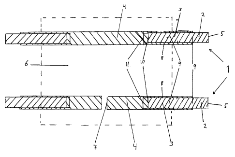
Reference is made to Figure 1, where it is illustrated a device 1 to conduct
current
to or from the electrodes of an electrolysis cell, which device provides both
increased
conduction of heat away from the electrolysis bath of the electrolysis cell
and reduced
5 electrical voltage drop, and thereby possibility for electrolysis at
increased current/current
density and reduced voltage drop, which device in the direction towards the
electrolysis
cell comprises three types of segments; at least one outer segment 2 joined
with at least
one intermediate segment 3 which again is joined with at least one inner
segment 4;
where the outer segment 2 has at least one end 5 which should extend out from
an
lo electrode body 6 towards an outer current circuit, and the outer segment is
coupled to at
least one intermediate segment 3 which again is coupled to at least one inner
segment
with at least one section 4 or end 7 in the electrode body; where the inner
segment 4 is
manufactured from steel, the intermediate segment is manufactured with a steel
lining 8
over an inner core of a material 9 with better electrical and thermal
conductivity than
steel, and the outer segment is manufactured from a material 9 with better
electrical and
thermal conductivity than steel, and the device or the components thereof has
optionally a
coating applied, and the device has optionally expansion joints or flexible
segments to
handle temperature induced movements,
and the device is distinguished in that the material 9 with better electrical
and
thermal conductivity than steel is chosen from the group consisting of
aluminium,
copper, silver, alloys and intermetals thereof, preferably pure aluminium and
soft copper,
the intermediate segment with core of the material 9 with better electrical
and
thermal conductivity than steel, extends into the electrode body, and
the joining between the inner segment and the intermediate segment is by means
of a friction weld or induction weld between the inner core of the
intermediate segment
and a steel insert with dimensions corresponding to said inner core, in that
the steel insert
in one end is friction welded or induction welded to the inner core of the
intermediate
section 10 and in the other end is friction welded or induction welded 11 to
the massive
inner steel segment, where the last mentioned weld also comprises the outer
steel lining
S.
The above mentioned steel insert will for some embodiments, where it is more
in
agreement with the common terminology in the art, be termed a small nipple.
Pure aluminium and soft copper, which melt at 658.5 C and 1083 C,
respectively, are preferably the materials to replace steel. Other materials
can also be
3s relevant, for example other aluminium alloys, alloys with lots of copper,
and silver, but in
particular the weldability and the costs are limiting factors. Aluminium
different from
pure aluminium can be useful, for example different aluminium alloys, such as
AA 6063,
but these will, however, in general provide lower quality welds with the
obligatory
welding methods, and provide reduced conductivity, and the increased strength
results in
SUBSTITUTE SHEET (RULE 26)
CA 02429696 2003-05-23
WO 02/42525 PCT/N001/00464
6
that by temperature induced movements of the steel are not so easily followed.
By similar
reasons soft, pure copper is preferred over for example electrolytic copper,
however, the
choice of type of copper or copper alloy is less critical than choice of
aluminium since
the weldability is better. Other materials, for example silver, are most
relevant as optional
coatings. However, it would be preferable to delimit the utilization of
different materials
to avoid contact voltage drops between different materials and to keep the
joining and
manufacturing simple. Therefore, it is in general most preferred to use pure
aluminium as
core in devices where the core temperature can be maintained below ca. 400 C
during
operation, and copper as core material where the temperature during operation
can be
io maintained under ca. 780 C, in both situations with an inner segment of
massive steel in
the direction towards the electrolysis bath. Devices with both steel, copper
and pure
aluminium in the core are useful, but in agreement with the above, only
preferred when
so are specified below. It is considered to be within the skill of the persons
in the art to
test different variations of the devices with steel, pure aluminium and/or
copper taking
into account the costs, voltage drop, temperature in the core, ease of
fabrication and
replacement, and other aspects mentioned or discussed herein.
The problems of pure electrical contact and probably also thermal between
better
conducting material and steel, appear to be solved by using friction welds or
induction
welds according to the invention. Thereby it is probably achieved better welds
over the
full cross-section, with significantly reduced content of oxides and other
unwanted
compounds. In the transition towards massive steel in the longitudinal
direction it is
required to utilize an intermediate section or an insert of massive steel, for
example a
smaller nipple having a diameter or a cross-section equal to or smaller than
the material
with better conductivity, because this surprisingly gives a significant
improvement with
respect to weldability and ease of fabrication. A uniform weld over the full
cross-section,
together with the preferred choice of materials and constructive features,
appear to be
essential. Optional problems by recrystallization of pure aluminium
surprisingly appear
to be eliminated by use of the welding methods and a process for manufacturing
according to the invention.
Conveniently 99.5 % by weight pure aluminium or aluminium of purer grade is
utilized, preferably 99.9 % by weight pure aluminium.
Electron beam welding or laser welding are possible alternative acceptable
welding methods.
In a preferred embodiment the steel insert between the inner core of the
intermediate segment and the inner segment is designed with a recession into
the inner
core of the intermediate segment, most preferred a convex recession 67, as
illustrated on
Figure S. Thereby increased welding area and improved mechanical, electrical
and
thermal joining is achieved.
SUBSTITUTE SHEET (RULE 26)
CA 02429696 2003-05-23
WO 02/42525 PCT/N001/00464
7
Further it might be preferable to have a point or an elevated centre area of
the
surfaces which are to be welded together by friction welding or induction
welding,
because this appears to result in reduced oxide content in the weld.
In the following some preferred embodiments of the invention are described in
further detail.
Reference is further made to Figure 2 which is an outline of an anode hanger 1
with six nipples, with a typical outside design, Figure 3 which is a section
of an anode
hanger with three nipples, and Figure 4 which is a section of another anode
hanger with
four nipples. On Figure 2 the transition towards massive steel nipple
according to the
io embodiments illustrated on Figures 3 and 4, respectively, is indicated in
one nipple for
each embodiment, respectively with the right hand hatch for Figure 3 and the
left hand
hatch for Figure 4. As indicated in Figure 2, the core of the material of
better
conductivity extends into most of the nipple length, as indicated for two of
the nipples.
Reference is made to Figure 3 which illustrates a device, characterized in
that it is
a device for conducting current to an anode of the prebaked type of carbon or
non-
carbon, more specific an anode hanger 12, for production of aluminium by
electrolysis,
where the device comprises an upper part 13 manufactured of pure aluminium or
copper,
a lower part 14, a so called yoke, where the upper parts of the yoke 14 have a
core 15 of
pure aluminium or copper with a steel lining 16, and the lower parts of the
yoke comprise
2o nipples 17 of massive steel; where the transition 18 from the upper part to
the core of the
yoke is without a bimetal transition, but instead is with a single weld pure
aluminium-
pure aluminium or copper-copper of the type friction weld, induction weld or
arc weld or
with a weld pure aluminium-copper of the type friction weld or induction weld
or is
designed in one massive piece; where the inner core 15 of pure aluminiuin or
copper in
the yoke 14 is shrink fitted into the outer steel lining 16 or the outer steel
lining is fitted
around the core, to the lower part of the core 15 it is friction welded or
induction welded
small steel nipples 19, whereto later larger massive steel nipples 17 have
been friction
welded or induction welded, where the nipples optionally have leaf-type design
or three
dimensional dendritic design or corrugated design, and where the upper part of
the device
is of pure aluminium or copper optionally having a large surface area and/or a
large
cross-section area for increased heat conduction, and/or with external
cooling, and the
device optionally has one or more expansion joints to take up temperature
induced
movements.
Further, reference is made to Figure 4, which illustrates a little different
device for conducting current to an anode of the prebaked type of carbon or
non-carbon,
more specific an anode hanger 20, for production of aluminium by electrolysis,
where the
device comprises an upper part 21 manufactured from pure aluminium or copper,
a lower
part 22, a so called yoke, where the upper parts of the yoke 22 have a core 23
of pure
aluminium or copper with a steel lining 24, and the lower parts of the yoke
comprise
SUBSTITUTE SHEET (RULE 26)
CA 02429696 2003-05-23
WO 02/42525 PCT/N001/00464
8
nipples 25 of massive steel; where the transition 26 from the upper part to
the core of the
yoke is without a bimetal transition, but instead is with a single weld pure
aluminium-
pure aluminium or copper-copper of the type friction weld, induction weld or
arc weld, or
with a weld pure aluminium-copper of the type friction weld or induction weld
or is
manufactured in one massive piece; where the inner core 23 of pure aluminium
or copper
of the yoke 22 is shrink fitted into the outer steel lining 24 or the outer
steel lining is
fitted around the core, to the lower part of the core 23 it is induction
welded small nipples
27 of steel, whereto later it have been induction welded larger massive steel
nipples 25,
where the small nipples 27 is recessed into the core of the yoke of pure
aluminium or
io copper in one end 28 and into the larger massive steel nipples in the other
end 29.
Another preferred embodiment of the device according to the invention, with
reference to Figure 5, is an anode bolt. More specific it is on Figure 5
illustrated an
anode bolt 30 (stud bolt) for conducting current to an anode of the Soderberg
type for
aluminium production by electrolysis of alumina solved into a melted fluoride
electrolyte, where the anode bolt comprises an upper part 31 of pure aluminium
and/or
copper with a lower part 32 with a core of pure aluminium and/or copper which
is shrink
fitted or enclosed into a steel lining 33, and a lower part 34 of massive
steel, where the
welded joint 35 towards the massive stee134 is in the form of a friction weld
or an
induction weld, via a smaller nipple 36 of steel, and where the surface 38
towards the
core optionally has been metallized and the surface 39 extending toward the
electrode
body optionally has a coating applied, for example a coating including
tungsten.
The optional outer coating provides better protection against upwardly rising
gases, for example oxygen, carbon dioxide and halogen containing gases, and up
to a
double life-time has been observed for anode bolts having such coating.
A third preferred embodiment of the device according to the invention is a
cathode
current bus bar (often termed cathode steel). Reference is made to Figure 6
which
illustrates a cathode bus bar 39 for conducting current from the cathode in a
cell for
production of aluminium by electrolysis of alumina solved in a melted
electrolyte, where
the device 39 comprises an inner segment 40 of steel, where the inner segment
in one or
3o both ends via a steel insert 40a is coupled to an intermediate segment 41
with a copper
core 42 covered with an outside steel lining 43, and an outer segment 44 of
copper
extending further out from the intermediate segment, in that the outer steel
lining 43 on
the intermediate segment comprises flat steel or iron/steel of other form
which is welded
thereon and which can enclose the inner copper core 42, where the flat stee143
is
3s metallized with copper on the surfaces 45 facing the copper core, where the
outer
segment 44 of the copper extends further out than the outer steel lining,
sufficient to that
by introduction into an electrolysis cell the outer segment 44 can extend out
from the wall
of the electrolysis cell while the steel lining just extends out from the wall
of the
electrolysis cell, where the extending copper ends 44 are designed to be
friction welded
SUBSTITUTE SHEET (RULE 26)
CA 02429696 2009-03-13
9
or induction welded to a part 46 of copper or pure aluminium which goes
directly into an
external current circuit or are designed for being coupled thereto via a cup
47 or a fish joint of
copper or pure aluminium, a threaded joint or a shell-joint.
The invention also comprises further embodiments within the spirit of the
invention and
scope of the present patent application. Some of the further embodiments are
illustrated on
Figure 7, where the reference numerals 48 to 53 illustrate anode hangers, the
reference numeral
54 illustrates a further anode bolt, and the reference numerals 55 to 59
illustrate cathode bus
bars. For the cathode bus bars it is illustrated, with reference numerals 55
to 59, coupling
towards the outer current circuit by quick connection, fish joint, a threaded
joint, induction
weld or a shell-joint, respectively.
Reference is also made to the Figures 8 and 9, which illustrate some further
cathode bus
bars 60, 61, 62, 63, with induction welded copper bolt or -rod of respectively
shorter or longer
length, and coupling to the outer current circuit, and a particularly
preferred cathode bus bar 64
according to the invention is illustrated on Figure 9, with 4 intermediate
segments and outer
segments orientated vertically downwards.
The cathode bus bar 64 comprises more than two intermediate segments 65
connected
to more than two outer segments 66, in that the intermediate segments and the
outer segments
extend vertically down from the electrode body or horizontally out from the
electrode body.
Thereby a particular low voltage drop and heat conduction is achieved.
The invention does also comprise methods particularly suitable for
manufacturing the
devices according to the invention, more specific the most preferred
embodiments thereof.
Accordingly the invention comprises a method for manufacturing an anode hanger
according to the invention whereby small steel nipples are friction welded or
induction welded
to massive pure aluminium bolt or copper bolt of equal diameter; the outer
steel lining is
optionally provided with a coating on the outside and the inside; the outer
steel lining is shrink
fitted or encased onto the inner core of pure aluminium or copper of the yoke;
the lower
massive steel nipples are friction welded or induction welded to the smaller
steel nipples and
the lower parts of the core of the yoke with outer steel lining; the upper
part is welded to the
pure aluminium or copper in the yoke, whereby the upper part of pure aluminium
or copper
either is going directly over into one or more of the nipples of the yoke,
whereto the remaining
nipples with a core of pure aluminium or copper are welded, or are welded
directly to the core
of the yoke, without an arc weld or fusion weld when joining different
materials, but with
friction weld or induction weld; the yoke is formed to its intended form,
preferably by
CA 02429696 2009-03-13
induction bending nipples in the area having a core of pure aluminium or
copper to intended
position, at choice before, in between or after welding.
The invention also comprises a method for manufacturing another anode hanger
5 according to the invention whereby small nipples of steel or copper are
induction welded to
massive pure aluminium bolt or copper bolt of larger diameter or cross-
section, wherein a
recession adapted to the smaller nipples has been preformed; the small nipples
of steel or
copper are induction welded to the massive steel nipples of larger diameter or
cross-section,
whereby it has been preformed recessions adapted to the smaller nipple in the
larger massive
10 steel bolt; the outer steel lining is provided with optional coatings on
the outside and inside; the
outer steel lining is shrink fitted or encased onto the inner core of the pure
aluminium or copper
of the yoke; the upper part is welded to the pure aluminium or copper of the
yoke, whereby the
upper part of pure aluminium or copper either goes directly over into one or
more of the
nipples of the yoke, whereto the remaining nipples having a core of pure
aluminium or copper
are welded, or are welded directly to the core of the yoke, without arc weld
or fusion weld
when joining different materials, but with friction weld or induction weld;
the yoke is formed
to its intended form, preferably by induction bending nipples in areas with
core of pure
aluminium or copper to intended position, at choice before, in between or
after welding.
Further, the invention comprises a method for manufacturing an anode bolt
according
to the invention whereby small steel nipples are friction welded or induction
welded to the
lower position part of pure aluminium or copper, whereby the steel nipples
have diameter equal
to or smaller than the pure aluminium or copper; whereby the lower part of
pure aluminium or
copper is shrink fitted into or is encased with an outer steel lining; whereby
a lower part of
massive steel is welded by friction or induction, via the steel nipple, to the
inner core of pure
aluminium or copper; whereby the lower part of pure aluminium or copper goes
directly over
to the upper part of pure aluminium or copper or is welded thereto, in the
case of welding
between equal materials, by induction, friction or arc welding, in the case of
weld between
different materials, by induction or friction; whereby optional coatings have
been pre-applied
to the steel surface around the circumference towards the inner core and on
the surface towards
the electrode body.
The invention also comprises a method for manufacturing a cathode bus bar
according
to the invention whereby the inner massive steel segment is prepared by arc
welding onto it a
steel sheeting, for example in a height of 50 mm, whereby the steel segment is
positioned
vertically and the steel sheeting is adapted with an opening for the inner
copper core of the
intermediate segment, where after the copper core with a steel insert
prewelded by friction or
CA 02429696 2009-03-13
11
induction is positioned into the sheeting and is induction welded to the inner
massive steel
core, in one or both ends, where after the copper core is lined with four
metallized flat irons or
flat steels, where after the four flat steels are pressed and held into
position against the inner
copper core under high pressure and high temperature, while the four flat
steels are arc welded
together, and the outer ends are prepared before or after according to the
intended type of
connection to the external current circuit.
Further, the invention comprises a cell for electrolytic production of
aluminium by
electrolysis of alumina solved in a melted electrolyte, distinguished in that
the cell comprises
anode hangers according to the invention and/or anode bolt according to the
invention and
cathode bus bars according to the invention. In a cell there are typically for
example 8 anode
hangers along each longitudinal side, which make a total of 16, or for cells
of the Soderberg-
type, 48 anode bolts. At present there are for example 6 to 48 cathode bus
bars per cell. The
numbers can be outside the above disclosures.
The invention also comprises a method for production of aluminium,
distinguished in
that the electrolysis cell according to the invention is utilized, whereby the
production is
undertaken at a relatively high current density or a high current, and a low
voltage drop and a
low anode-cathode distance.
Dimensions, cross-sections and number of the devices according to the
invention, and
the methods for preparation, are typical according to the prior art, or can be
chosen based on
typical considerations by skilled persons, with the proviso that the
distinctive features of the
invention are maintained.
Example
An anode hanger according to the invention was prepared by the preferred
method of
the invention described for the device. Friction welding was used for joining
towards the
massive steel nipples and a smaller steel nipple, and from the smaller steel
nipple to the core of
99.5 % by weight pure aluminium. Measurements of electrical parameters were
between the
points a and b on Figure 3, and the temperature was measured under b in Figure
3. The massive
bolt of pure aluminium in the core of the nipples had a diameter of 100 mm,
the friction welded
smaller steel nipple had a diameter of 100 mm and a length of 50 mm, the outer
steel lining
was a pipe with an outer diameter of 140 mm and an inner diameter of 100 mm.
The lower
massive steel nipple had a diameter of 140 mm. The upper part with dimensions
of 170 x 120
mm of pure aluminium was arc welded to the yoke and the upper part of the yoke
was encased
with a steel lining by manual arc welding. Remark that the specified
dimensions are only
CA 02429696 2009-03-13
lla
typical dimensions for an anode hanger, and that dimensions may vary
considerably. The
friction welding was performed with equipment and procedures from Black's
Equipments,
Doncaster, England. The results of the measurements are given in the Tables I
and 2.
As it appears from Table 1 the resistance over the fixed measurement distance
was
reduced from typically 5-6 micro ohm to typically 1.3 micro ohm. In a cell it
is typically 16
anode hangers and the total current of the cell is typically ca. 150 kA. The
voltage drop over
the anode hanger is reduced by ca. 30 mV, and calculated according to
Faraday's law of
electrolysis this amounts to more than 1.5 ton additional aluminium per
CA 02429696 2003-05-23
WO 02/42525 PCT/N001/00464
12
year per cell. For a typical plant having for example 600 ovens this amounts
to 900 tons
extra aluminium. The current efficiency will increase by ca. 1.5 %.
Table 1
Electrical parameters, measured values
According to the Voltage, Current Resistance
invention mV KA micro ohm
Yes 9-9-9 6.0 1.5
Yes 12-10-10 7.4 1.5
Yes 10-8-10 9.3 1.0
Yes 9-8-10 6.8 1.3
Yes 13-11-13 7.3 1.7
Yes 13-12-13 7.4 1.7
No, standard 40-36-46 8.3 4.5
anode hanger
No, standard 47-38-57 7.9 6.0
anode hanger
No, standard 44-39-46 7.6 5.7
anode hanger
Table 2
Temperature measurements in C
Anode hanger Outer nipple Intermediate nipple Inner nipple
According to the 268 221 238
invention
According to the 297 287 318
invention
Standard, not according to 371 410 362
the invention
It is assumed that the improvements are due to better possibilities as a
result of the
invention for performing electrolysis at high current, low voltage drop and
low anode-
cathode distance, without creation of process disturbances.
SUBSTITUTE SHEET (RULE 26)
CA 02429696 2003-05-23
WO 02/42525 PCT/N001/00464
13
As it appears from Table 2 it is a significant reduction of temperature in the
nipples with the anode hanger according to the invention, in that the
reduction of
temperature was in the range from 44 to 189 C. The temperature in the nipple
was
reduced from in average 381 C to in average 272 C. The implications are
significant
with respect to current and heat losses, for example it is possible to
increase the current
strength without occurrence of process disturbances. The temperature reduction
is due to
that pure aluminium is a far better heat conductor than steel. A somewhat
similar effect
will be achieved with copper. It is considered that conditions with respect to
further
reduced flow velocities in the melt results in further decrease in heat
transfer number
io bath/coating (crust) and metal/coating, which increase the demand for
better heat
conduction through the current conducting devices.
Skilled persons may based on the patent claims and the description with
enclosed
figures be able to set forth many different embodiments which are not
specifically
described but are inside the spirit and scope of the invention as these appear
from the
1s patent claims. For example it may be useful to exclude the inner segment of
massive
steel, whereby the device may have an outer segment, with a steel lining on
the inner
part, of pure aluminium or copper, induction- or friction welded to the
intermediate
segment of preferably copper, with a steel lining. Further, it would be
preferable with a
copper coating towards the anode beam on the anode hangers and the anode bolts
with
20 the upper segment of pure aluminium, where the copper coating
(metallization) is formed
to a plough form pointing upwards to lead away oxide and other matter from the
contacting area towards the anode beam, in addition to that repair of the
scratches on the
contact surface can be made easier and at lower costs. Further, the steel
lining on the
intermediate segment on the devices according to the invention can be rolled
to the inner
25 core at high temperature and high pressure, in particular for embodiments
with a circular
cross-section. Circular cross-sections may be preferable with respect to the
cost for the
raw materials. Compared to the prior art the devices according to the
invention are
preferable even though the intermediate segment is not extending into the
electrode body,
but is joined towards the inner segment at the outside of the electrode body.
Accordingly,
3o also embodiments which only in part make use of the distinguishing features
of the
invention, can be preferable compared to prior art.
SUBSTITUTE SHEET (RULE 26)