Note: Descriptions are shown in the official language in which they were submitted.
CA 02430000 2009-12-04
RETARDER, PARTICULARLY PROVIDED AS A BRAKING DEVICE OR
AUXILIARY BRAKING DEVICE FOR VEHICLES OR THE LIKE,
ESPECIALLY RAIL VEHICLES
Specification
The invention relates to a retarder, as a braking
device or auxiliary braking device for vehicles or the
like, in particular rail vehicles, having a stator
comprising at least two axially spaced-apart stator
halves, which each have magnetic field coils, and a rotor
which is disposed between the at least two stator halves,
the rotor being coupled in a manner fixed against relative
rotation to an axle or shaft of the vehicle and the stator
being coupled with the vehicle, or an undercarriage of the
vehicle.
The term "retarder" is understood herein to be an
electrical eddy-current brake, which is intended to
reinforce or replace the service brake, for instance of
rail vehicles, utility vehicles, or the like in certain
situations. The braking action of a retarder arises from
the buildup of a magnetic field, which counteracts the
rotation of a rotor because of the induction of eddy
currents in the rotor. The rotor is connected, for
instance to the cardan shaft of the vehicle, in a manner
fixed against relative rotation. The magnetic field can
be generated for instance by four magnet coils or pairs of
magnet coils, which can each be added in succession
depending on the braking power individually required. One
such retarder is described in detail in German Patent
Disclosure DE 39 08 234 Al, for instance.
From Japanese Patent Disclosure JP 61266064, a rotor
with the characteristics recited at the outset is already
known. According to this, it is provided that an eddy
current brake be used in a rail vehicle; the rotor is
1
connected to the wheel axle in a manner fixed against
relative rotation, and the stator comprises coils disposed
on both sides of the rotor. A disadvantage of the known
apparatus is the low braking action, which can be ascribed
to the fact, among others, that the coils are distributed
over only approximately a semicircle of the rotor.
With this as the point of departure, it is the
object of the invention to disclose an eddy current brake
of the type defined at the outset, which is distinguished
by strong braking action, a compact design, and high
operating performance. In addition, the eddy current
brake of the invention should be suitable in particular
for rail vehicles.
In the retarder having the characteristics recited
at the outset, this object is attained according to the
invention essentially in that the rotor is formed by at
least one rotor disk divided into two parts, comprising
two adjacent rotor halves, which are joined to one another
in a radially inner annular region, oriented toward the
axle or shaft, in particular by means of a screwing means
or similar connecting means, and are disposed in a
radially outer annular section, which is essentially
adjacent to the magnetic field coils of the stator, with
axial clearance from one another.
Because of these provisions, a retarder with a
strong braking action, compact structure and high
performance is made available that is especially well
suited to rail vehicles. Because of the special design of
the rotor as a rotor disk divided in two, where the outer
annular sections are disposed with axial clearance from
one another, it is assured that the rotor can withstand
the thermal stress that occurs from the heat development
during the activation of the retarder. Because of this
provision of the axial spacing apart of the outer annular
sections of the two rotor halves, the possibility of a
relative motion of these rotor halves to one another is
afforded; this relative motion occurs as the result of
variable thermal expansion, especially at high braking
2
CA 02430000 2003-05-26
capacities. Moreover, in the region of the clearance
located between the rotor halves, the rotor can undergo
additional cooling. It is assured by the invention that
the rotor halves of the rotor have a certain flexibility
in the axial direction, so that forces of gravity or the
like that can occur because of the thermal stress will be
taken into account.
In a first advantageous refinement of the invention,
disposed on an outer side of the essentially annular
stator, or of the respective outer stator half, is a
further outer, preferably one-piece rotor disk, which is
connected in a manner fixed against relative rotation to
the axle or shaft. In particular, the laterally outward-
oriented magnetic fields of the stator, or of the adjacent
stator halves, are likewise utilized to generate a braking
moment, since further rotor disks, which are preferably
embodied in one piece, are positioned in these outer
regions of the stator or of the stator halves.
In another aspect, associated with the stator, or
the two stator halves, axially spaced apart from it, is a
further stator section, which is comparable in shape and
structure to the stator halves, so that a second rotor
disk, divided into two parts and connected in a manner
fixed against relative rotation to the axle or shaft, is
disposed in a gap formed by one stator half and the
further stator section. In this embodiment, middle rotor
disks divided in two are thus provided, which are disposed
in the interior of a stator in three pieces. The
possibility additionally exists of providing two further,
outer rotor disks on the outside of the two outer stator
sections of the stator that is divided into three pieces.
Overall, the braking moment of the retarder can be
increased considerably as a result, with only an
insignificant increase in the structural size.
For mechanically stabilizing the two rotor halves of
the rotor disk, which is at least divided into two pieces,
in the region of the radially outer annular sections
oriented toward one another, it is attractive in an
3
CA 02430000 2003-05-26
advantageous feature of the invention to provide a
toothing geometry, in particular a corresponding and
partly meshing toothing and counterpart toothing, which
preferably have a circular- annular structure. Because of
this provision, the mechanical stability of the rotor
divided into two pieces is increased considerably, and in
addition the surface area between the two rotor halves is
increased because of the toothing structure provided.
It is also especially advantageously attractive that
the rotor, in particular the rotor disks or rotor halves
of the rotor, and/or the stator as well, in particular the
stator halves or the stator section, are formed by
components that are divided in the radial direction and
that after installation are solidly joined to one another
by connecting means. Because of this provision, the
retarder can for instance be mounted on the axle of a rail
vehicle without having to take off the wheel sets to do
so.
Advantageously, the stator and in particular the
stator halves or the stator section are joined to the
vehicle or to an undercarriage via adjustable mounts.
It is also recommended that the stator is connected
to a wheel suspension, or is fixed on it, via variable or
adjustable tightening elements. This provision,
particularly in conjunction with the use of the retarder
in rail vehicles, proves advantageous because in freight
trains, for instance, the axles can shift by several
decimeters in the axial direction relative to the
undercarriage or car. Because of this provision, there is
accordingly no need to provide some arrangement with which
the stator can follow such relative shifts. Instead,
because of its connection to the wheel suspension, the
stator is subjected to the same displacements as the
rotor. Particularly, in a railroad car, it is attractive
that the retarder is assigned its own power supply for
supplying the magnetic field coils and optionally the
electronic controller of the retarder, which power supply
is preferably formed by a generator and optionally
4
CA 02430000 2003-05-26
downstream accumulators, since as a rule these cars have
no power supply of their own. The generator can be driven
via the axle or shaft, for instance.
Particularly whenever the retarder is used in a
locomotive, it is attractive that an intermediate gear is
disposed between the axle or shaft and the retarder. In
such locomotives, there is a generator for power supply
purposes anyway, so that the generator need not be
furnished separately.
In another advantageous feature of the invention,
the retarder is encapsulated in a housing, preferably
comprising aluminum or the like, and the rotor disks are
acted upon by a fluid bath, in particular by a coolant
fluid. Because of this provision, the thermal stress on
the retarder that occurs in the braking event can be
minimized, since special cooling of the rotor disks is
made possible by means of the coolant fluid.
In still another advantageous feature of the
invention, by means of a pump, such as an electric pump,
the coolant fluid is circulated in a closed loop between
the housing and a heat exchanger by which the thermal
energy can be extracted from the retarder securely and
quickly.
In a constructive feature of the invention, it
proves advantageous that the rotor disks are secured to
the axle or shaft by means of tightening elements, and
inner and outer annular elements are provided which can
preferably be wedged to one another in the axial direction
via corresponding oblique faces or conical faces, in
particular by means of screws or similar means. By
tightening these screws, for instance, in conjunction with
the conical outer jacket faces of the inner and outer
annular elements, a pressing force in the direction of the
axle or shaft is exerted on the outer annular element.
The rotor disks are secured to the respective outer
annular elements by means of a screw fastening or the
like.
It has also proved advantageous that a needle
CA 02430000 2003-05-26
bearing is disposed between the outer annular element and
the annularly embodied stator, or similar bearing.
Further objects, advantages and possible
applications of the present invention will become apparent
from the ensuing description of exemplary embodiments in
conjunction with the drawings. All the characteristics
described and/or shown in the drawings, on their own or in
arbitrary useful combination, form the subject of the
present invention, regardless of how they are summarized
in the claims or what the claims dependencies are.
Shown are:
Fig. 1, an elevation view of one possible embodiment
of an eddy current brake of the invention, disposed on an
axle of a rail vehicle;
Fig. 2, a side view of the eddy current brake of
Fig. 1;
Fig. 3, a.plan view on the eddy current brake;
Fig. 4, a longitudinal section through the eddy
current brake of Fig. 1;
Fig. 5, a longitudinal section through a further
embodiment of an eddy current brake of the invention,
disposed on an axle of a rail vehicle;
Fig. 6, a longitudinal section through an eddy
current brake of the invention with integrated cooling;
Fig. 7, a plan view on a further embodiment of an
eddy current brake of the invention;
Fig. 8, a schematic view of an eddy current brake of
the invention, disposed on the undercarriage of a
locomotive; and
Fig. 9, a middle rotor disk, in section with
toothing geometry.
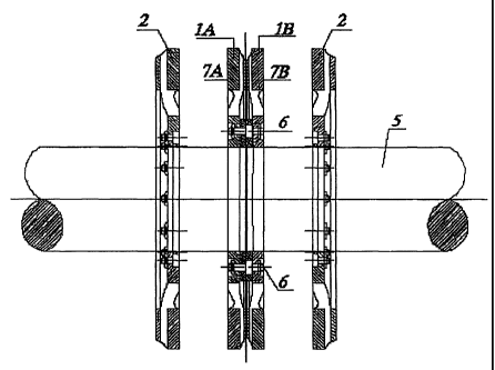
The retarder of Fig. 1 has a number of magnet coils,
which are mounted concentrically about a shaft or for
instance an axle 5 of a rail vehicle on annular coil
bodies or stators 3. One outer rotor disk 2, which is
connected to the axle 6 in a manner fixed against relative
rotation, is located at a slight spacing in front of the
poles of the coils on each of the outer two sides of the
6
CA 02430000 2003-05-26
CA 02430000 2003-05-26
stator 3. The stator housing is divided into two pieces,
so that between the two stator halves 3a, 3b, there is a
middle rotor disk 1, which is likewise connected to the
axle 5 in a manner fixed against relative rotation.
When the coils are excited by electrical current,
magnetic fields with alternating field directions occur at
each of the poles located on the same face ends of the
coil packets. In the braking event, eddy currents are
then induced in the rotor disks 1, 2 that rotate in these
nonhomogeneous magnetic fields, and the eddy currents
exert a braking moment on the rotor disks 1, 2 that is
transmitted to the axle 5.
Fastening the stator halves 3a, 3b of the stator is
done by means of a mount 4, for instance on the chassis of
a rail vehicle or motor vehicle.
It can be seen from Fig. 4 that the middle rotor 1
is embodied in two parts, with one rotor half la and a
second rotor half lb. The two rotor halves la, lb are
joined together in the radially inner region by means of
screwing means 6. On their radially outer ends, in the
region of the annular sections 7a, 7b opposite the pole
plates of the coils, the two rotor halves la, lb are
movable in the axial direction, which can be attained for
instance by means of a special toothing geometry 20 of the
parts contacting one another of the rotor halves la, lb.
It is understood that the middle rotor disk 1, like the
outer rotor disk 2, has cooling conduits for aspirating
cooling air.
By means of the axial mobility of the rotor halves
la, lb of.the middle rotor disk 1, it is attained that in
operation of the retarder, at the attendant high
temperatures between the pole plates of the stator 3 and
the adjoining annular surface of the respective rotor
disks 1, 2 or rotor half la, lb, the same geometric
conditions can become established, so that overall, the
same braking action originates at each rotor 1, 2, or each
rotor half la, lb.
The variant of Fig. 5 is distinguished from the
7
version of Figs. 1-4 in that the rotor disks la, lb, 2 are
mounted on the axle 5 of the rail vehicle via clamping
rings. Annular elements, which comprise an outer annular
element 9 and an inner annular element 10, are associated
with the individual rotors la, lb, 2 and the stators 3.
The outer jacket of the inner annular element 10 is
embodied conically. The outer annular element 9 comprises
half-shells, which are fixed by means of a toothing, or
set of teeth and an axially extending retaining element.
By tightening each screw 8, in conjunction with the
conical outer jacket face of the inner annular element 10,
a pressing force onto the axle 5 is exerted onto the outer
annular element 9. The fastening of the rotors 2 to the
respective outer annular elements 9 is done by means of
screwing means 6.
A bearing, preferably a needle bearing 11, is
additionally located between the outer annular element 9
and the stators 3.
The mounting of the stators 3 is not done to the
chassis, since in freight trains the axles 5 can shift
axially by more than approximately 42 mm. Instead,
tightening elements are provided, which are fixed to the
wheel suspension and can also be retightened.
Since railroad cars, both freight cars and as a rule
passenger cars as well, have no power supply of their own,
it is recommended according to the invention that an
electric generator be provided in addition, for supplying
the coils of the retarder and for supplying the
electronics for controlling the retarder and its
associated accumulator.
The variant of Fig. 6 differs from the variant of
Fig. 5 essentially in that the retarder is encapsulated by
means of a housing 21, and the rotor disks la, lb, 2 run
in a fluid bath 12 for the sake of cooling. A coolant
fluid 13 serves not for braking the rotors, as in
hydrodynamic retarders, but instead serves solely to cool
the rotor disks la, lb, 2. As the material for the
encapsulation, aluminum or the like can be considered, to
8
CA 02430000 2003-05-26
enable good heat dissipation in addition. The coolant
fluid 13 is brought into circulation by means of an
electric pump 14 and delivered to a heat exchanger 15. It
can be appreciated that for the rotation of the rotors la,
lb, 2 in the fluid bath 12, suitable seals are provided on
the outer housing.
Both the suspension and the energy supply are done
here as in the variant of Fig. 5.
In the exemplary embodiment of Fig. 7, two such
middle rotor disks 1, embodied as rotor pairs la, lb, are
disposed in the interior of the retarder, and as a result,
for comparable geometric dimensions, the braking force of
the rotor and thus its performance can be enhanced still
further.
It is understood, however, that it is also possible
for the retarder 16, as shown schematically in Fig. 8, to
be disposed on the undercarriage 19 of a rail vehicle,
especially a passenger car; in that case, an intermediate
gear 17 is provided between the retarder 16 and the axle
5. The generator 18, which already exists in such rail
vehicles at present, for the power supply is located on
the side opposite the retarder 16.
9
CA 02430000 2003-05-26
List of Reference Numerals
1 - Middle rotor disk
la - Rotor half
lb - Rotor half
2 - Outer rotor disk
3 - Stator
3a - Stator half
3b - Stator half
3c - Stator section
4 - Mount
- Axle
6 - Screw fastening
7a - Annular section
7b - Annular section
8 - Disk
9 - Annular groove
- Annular groove
11 - Needle bearing
12 - Fluid bath
13 - Cooling fluid
14 - Electric pump
- Heat exchanger
16 - Retarder
17 - Intermediate gear
18 - Generator
19 - Undercarriage
- Toothing geometry
21 - Housing
CA 02430000 2003-05-26