Language selection

Search

Patent 2430041 Summary

Third-party information liability

Some of the information on this Web page has been provided by external sources. The Government of Canada is not responsible for the accuracy, reliability or currency of the information supplied by external sources. Users wishing to rely upon this information should consult directly with the source of the information. Content provided by external sources is not subject to official languages, privacy and accessibility requirements.

Claims and Abstract availability

Any discrepancies in the text and image of the Claims and Abstract are due to differing posting times. Text of the Claims and Abstract are posted:

  • At the time the application is open to public inspection;
  • At the time of issue of the patent (grant).
(12) Patent Application: (11) CA 2430041
(54) English Title: ATOMIZED LIQUID BOILER
(54) French Title: CHAUDIERE A LIQUIDE ATOMISE
Status: Deemed Abandoned and Beyond the Period of Reinstatement - Pending Response to Notice of Disregarded Communication
Bibliographic Data
(51) International Patent Classification (IPC):
  • F22B 29/00 (2006.01)
  • B01B 01/00 (2006.01)
  • B01D 01/14 (2006.01)
  • F22B 01/18 (2006.01)
(72) Inventors :
  • MOODY, EUGENE I. (Canada)
(73) Owners :
  • EUGENE I. MOODY
(71) Applicants :
  • EUGENE I. MOODY (Canada)
(74) Agent: MARKS & CLERK
(74) Associate agent:
(45) Issued:
(22) Filed Date: 2003-05-26
(41) Open to Public Inspection: 2004-11-26
Availability of licence: N/A
Dedicated to the Public: N/A
(25) Language of filing: English

Patent Cooperation Treaty (PCT): No

(30) Application Priority Data: None

Abstracts

Sorry, the abstracts for patent document number 2430041 were not found.

Claims

Note: Claims are shown in the official language in which they were submitted.
Sorry, the claims for patent document number 2430041 were not found.
Text is not available for all patent documents. The current dates of coverage are on the Currency of Information  page

Description

Note: Descriptions are shown in the official language in which they were submitted.


p a
CA 02430041 2003-05-26
ATOMIZED LIa~UID BOILER
FIELD OF THE INVENTION
This invention relates to the use of a pressurized gas to deliver a liquid
to a heated surface for the purpose of vaporizing the liquid.
BACKGROUND OF THE INVENTION
Heating a liquid to the point of vaporization has traditionally been
accomplished by introducing large volumes of liquid in coalesced or atomized
form to a heated surface. This process takes place within an enclosed space
commonly referred to as a boiler or steam generator. The resulting vapor
can then be delivered to demand points where the heat or work energy of the
vapor is used:
In processes where a coalesced liquid is introduced to a heated
surface, most of the liquid component is used to transport that portion of the
liquid which is to be vaporized. In doing so, most of the heat energy is
consumed by the transport molecules, not the vaporized molecules.
When an atomized Liquid is applied fo a heated surface, it is impossible
to have an even distribution of the liquid and thus it coalesces. This results
in
a similar problem as that described above where heat energy is lost to the
liquid component.
It is clear that traditional methods of vaporization have inherent
drawbacks associated with loss of heat energy. This loss of heat energy
ultimately drives upwards the cost of the overall process. Thus, there is a
clear need for a process that more efficiently utilizes the heat energy to
accomplish the task of vaporization.
SUMMARY OF THE INVENTION
In accordance with an aspect of this invention, a liquid boiler apparatus
for vaporizing a liquid, said apparatus comprises:
a heat source,
a boiler heated by said heat source,
1

CA 02430041 2003-05-26
said boiler being adapted to receive a liquid in mist or droplet form and
a transport gas,
wherein said transport gas facilitates movement of said liquid through
said boiler, and wherein said liquid is vaporized and subsequently delivered
to a demand point.
BRIEF DESCRIPTION OF THE DRAWINGS
Preferred embodiments of the invention are shown in the drawings
wherein:
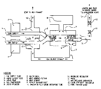
Fig. 1 is a schematic of a liquid-tube boiler configuration where the
gaslliquid mixture passes through a heat source.
Fig. 2 is a schematic of a firetube boiler configuration where the
gas/liquid mixture passes around a heat source.
DETAILED DESCRIPTION OF THE PREFERRED EMBODLMENTS
As shown in Figures 1 and 2, a transport gas is supplied through gas
inlet tube 1 while a liquid to be vaporized is supplied through liquid inlet
tube
2. In order to convert the liquid into mist or droplet form, the liquid
component
passes through an atomizer 5. Upon leaving the atomizer 5, the atomized
liquid mixes with the transport gas in mixing area 16. The transport gas
serves to facilitate transport of the atomized liquid through the apparatus.
The atomized liquidltransport gas mixture is transported to the heated boiler
area 6 causing the atomized liquid to vaporize. To enter the heated boiler
area 6; the gas and liquid components are delivered at sufficient pressure so
as to overcome any back-pressure within the vaporization apparatus. The
delivery of the gas component may be accomplished using a compressor 4
while the delivery of the liquid component may be facilitated using pump 3.
Alternatively, the gas may originate from a pressurized source, eliminating
the
need for a compressor. To assist in providing sufficient heat energy for
vaporization, the gas and liquid components are subjected to a pre-heat
exchanger before entering the boiler area 6. Gas supplied through gas inlet
tube 1 passes through gas pre-heat exchanger 13 while liquid supplied
2

CA 02430041 2003-05-26
through liquid inlet tube 2 passes through liquid pre-heat exchanger 14.
The vaporized liquid/transport gas mixture exits the heated boiler area
fi through discharge tube 10. The apparatus is capable of producing
vaporized liquidltransport gas mixtures of various pressures depending on the
end use. One embodiment has end-pressures in the range of 2000-3000 psi.
The discharge pressure is adjustable to suit a particular application: In one
embodiment, as the mixture moves through discharge tube 10, the pressure
is adjusted using a pressure regulator 11 and a valve 12 before the vaporized
mixture continues to an application point where the work or heat energy is
consumed.
The boiler may be of either liquid tube configuration (Fig. 1 ) or fire tube
configuration (Fig. 2). In either configuration a heating medium 8 (i.e. hot
gases, hot liquids) heats boiler area 6 by flowing through plenum 7,
losing/transferring heat energy to boiler area 6. The heat medium then
moves through discharge duct 9 to gas pre-heat exchanger 13 and liquid pre-
heat exchanger 14, ultimately continuing to discharge duct 1 fi.
The heated gas/liquid vaporized mixture. is then directed to a demand
point where the heat or work energy of the vapor is used. Examples of.heat
energy-based applications include heating buildings or other secondary
mediums. Examples of work energy-based applications include the powering
of steam turbines or reciprocating steam engines.
The process of the current invention has certain advantages over prior
steam generating technologies. The first advantage is that only the amount
of liquid that.can be vaporized immediately on contact with the heated surface
is allowed to enter the boiler. Secondly, the liquid is transported by a
pressurized gas and does not have the opportunity to coalesce as it is in
constant motion within the boiler. Thirdly, the absence of coalesced water
means substantially all the heat energy at the point of contact between the
liquid molecule and heated surface is transferred for the purpose of
vaporization and not to pre-heat liquid molecules transporting those to be
vaporized. These advantages translate into increased heating efficiency and
lower overall cost.
3

CA 02430041 2003-05-26
Although preferred embodiments of the invention have been described
herein in detail, it will be understood by those skilled in the art that
variations
may be made thereto without departing the spirit of the invention.
4

Representative Drawing
A single figure which represents the drawing illustrating the invention.
Administrative Status

2024-08-01:As part of the Next Generation Patents (NGP) transition, the Canadian Patents Database (CPD) now contains a more detailed Event History, which replicates the Event Log of our new back-office solution.

Please note that "Inactive:" events refers to events no longer in use in our new back-office solution.

For a clearer understanding of the status of the application/patent presented on this page, the site Disclaimer , as well as the definitions for Patent , Event History , Maintenance Fee  and Payment History  should be consulted.

Event History

Description Date
Inactive: IPC from MCD 2006-03-12
Application Not Reinstated by Deadline 2005-12-21
Inactive: Dead - Application incomplete 2005-12-21
Deemed Abandoned - Failure to Respond to Maintenance Fee Notice 2005-05-26
Deemed Abandoned - Failure to Respond to Notice Requiring a Translation 2004-12-21
Application Published (Open to Public Inspection) 2004-11-26
Inactive: Cover page published 2004-11-25
Inactive: Incomplete 2004-09-21
Inactive: Courtesy letter - Evidence 2003-12-01
Inactive: First IPC assigned 2003-08-01
Inactive: IPC assigned 2003-07-31
Application Received - Regular National 2003-06-27
Inactive: Filing certificate - No RFE (English) 2003-06-27

Abandonment History

Abandonment Date Reason Reinstatement Date
2005-05-26
2004-12-21

Fee History

Fee Type Anniversary Year Due Date Paid Date
Application fee - small 2003-05-26
Owners on Record

Note: Records showing the ownership history in alphabetical order.

Current Owners on Record
EUGENE I. MOODY
Past Owners on Record
None
Past Owners that do not appear in the "Owners on Record" listing will appear in other documentation within the application.
Documents

To view selected files, please enter reCAPTCHA code :


To view images, click a link in the Document Description column (Temporarily unavailable). To download the documents, select one or more checkboxes in the first column and then click the "Download Selected in PDF format (Zip Archive)" or the "Download Selected as Single PDF" button.

List of published and non-published patent-specific documents on the CPD .

If you have any difficulty accessing content, you can call the Client Service Centre at 1-866-997-1936 or send them an e-mail at CIPO Client Service Centre.

({010=All Documents, 020=As Filed, 030=As Open to Public Inspection, 040=At Issuance, 050=Examination, 060=Incoming Correspondence, 070=Miscellaneous, 080=Outgoing Correspondence, 090=Payment})


Document
Description 
Date
(yyyy-mm-dd) 
Number of pages   Size of Image (KB) 
Abstract 2004-11-25 1 2
Claims 2004-11-25 1 2
Description 2003-05-25 4 172
Drawings 2003-05-25 2 52
Representative drawing 2003-10-01 1 14
Filing Certificate (English) 2003-06-26 1 158
Reminder of maintenance fee due 2005-01-26 1 109
Courtesy - Abandonment Letter (incomplete) 2005-01-10 1 166
Courtesy - Abandonment Letter (Maintenance Fee) 2005-07-20 1 175
Correspondence 2003-06-26 1 13
Correspondence 2004-09-16 1 18