Note: Descriptions are shown in the official language in which they were submitted.
CA 02430076 2005-07-18
LIGHT WITH A TRANSPARENT PANEL
The present invention relates to a light (luminaire) with a
light source or connection means therefor and a transparent
panel extending transversely to the direction of emission.
A light of this type belongs to a known lighting technology
principle and is described for example in DE 299 06 884 U.
An essential part of such a light are at least one
receptacle for at least one light source that generates the
light required to illuminate a space (room), a transparent
panel that is arranged between the receptacle and the space
to be illuminated and whose outer surface facing the space
forms an emission surface, and a base member on which the
light source or connection means therefor and the panel are
secured.
With known lights of the above type the panel of the light
is arranged so that it is enclosed by the base member. The
panel in many cases is secured to the base member in such a
way that it rests against an inner arm of the base member
extending roughly parallel to the panel.
With built-in lights an edge strip in the form of an outer
arm may optionally in addition project outwardly from the
base member roughly parallel to the panel, which serves to
cover the installation gap of an installation opening so
that the installation gap is not visible from the
surrounding space.
In these modifications the base member comprises edge strips
that are visible from the space to be illuminated, which
strips are arranged in the case of a light of a lighting
fascia on at least two oppositely facing sides of the light,
and in the case of an
CA 02430076 2003-05-27
WO 02/44612 PCT/EP01/13753
2
individual light are arranged over the whole perimeter
of the light and are visible as dark regions especially
when the light is on.
A light panel is described in DE 296 02 576 U1 that is
inserted into a ceiling covering and has a flat dome-
shaped reflector, a light source arranged therein and a
glass panel whose width corresponds to the width of the
reflector and that rests on flat edge sections of the
reflector. The panel and the reflector, which in their
edge regions are thus superimposed on one another in a
sandwich-like arrangement, are secured to the underneath
of a holding frame that is in turn secured to the
existing ceiling.
During operation of an installed light a light pattern
prQduced by the luminous radiation that is of varying
brightness and/or variously bright lit surfaces is/are
generated at the emission surface of the panel, which
are caused by the light source appearing as a surface or
profile and by its environment or the reflecting
surface. On the one hand this is attributed to the fact
that the light intensity of the light emitted at the
emission surface of the panel is greater in the
immediate region of the light source than adjacent to
the light source, which as a rule is arranged in the
central region of the panel, i.e. in the lateral regions
of the emission surface. Secondly, this is attributed
to the fact that the distance between the light source
and the panel increases in the lateral regions of the
panel and the light is incident at smaller angles on the
panel and has to illuminate a larger surface.
CA 02430076 2008-06-19
Jun-19-08 07:04pm From-SIIv6AS T-495 P.005/010 F-873
3
a=n order to homogenise the light pattern it is already
known to provide a diffuse or opal panel. Although
differences in the light panel and diferences in the
brightness caused for example by the structure of the
light source are reduced, nevertheless in practise the
light is undirected, with the result that a certain
amount of glare occurs. The latter in any case
interferes if the light is observed at a low angle from
the side.
The object of the invention is to improve a light in
terms of glare suppression. The invention also aims to
avoid or at least reduce differences in the light
pattern, for example recognizable structures of the light
source, and differences in the brightness of the light
pattern_
This object is achieved by a light constructed in
accordance with the present invention_
Accordingly, in one aspect of the present invention there
is provided a light, comprising:
a light source or connection means therefor;
a transparent panel extending transveraely to a
directian of light emission, provided with a
microstructure shaped to direct light in a single
direction; and
a reflector that comprises reflecting surfaces,
wherein light homogenization means are provided that
ensure that a light intensity of light entering the
transparent panel is roughly equal in all parts of the
transparent panel, and wherein the light homogenization
means are formed by an opal inner panel or an opal inner
film arranged between the light saurce and the
CA 02430076 2008-06-19
Jun-19-08 Ot:04pm From-SIIBAS T-495 P.006/Ot0 F-8T3
3a
transparent panel and resting in an inside on or against
the transparent panel, and wherein the light
homogenization means are furthe=ore formed by one of a
covering, a layer and a grid, wherein the grid is
reflecting or partially reflecting.
Lights with panels having a microstructure have only
recently been introduced onto the market. In these
lights the light shines laterally or from a narrow side
IO onto the panel, and the light exits broadside at the
microstructure of the panel in a substantially glare-free
manner.
The invention is ba:aed ari the knowledge that this effect
is also utilisable and advantageous for a generic light
according to the invention. In the modifications
according to the invention light from the at least one
light source passes transversely through the panel
CA 02430076 2003-05-27
WO 02/44612 PCT/EPO1/13753
4
comprising the microstructure, the light rays being
emitted at the emission surface without any significant
glare. In order to avoid or at least to reduce
variously bright regions of the light pattern
recognisable at the emission surface during operation of
the light and caused for example by the light source
itself, it is advantageous to provide the transparent
panel not only with a microstructure, but also with
light homogenisation means that ensure that the amount
of light or intensity of the light entering the panel is
approximately equal in all parts of the panel. In this
way variously bright regions and structures in the light
pattern recognisable at the emission surface of the
light during operation are avoided or at least reduced.
Several modifications that in each case individually and
also in combination achieve the object are proposed
according to the invention. The light homogenisation
means may thus be formed by various measures, which may
be used alternatively or in combination.
A first possibility consists in the use of a film having
a scattering effect, which can be arranged directly on
the inside of the panel or spaced therefrom. The
scattering effect may be different at different places
and may be adapted to the respective amount of light or
light intensity of the light occurring there.
Another light homogenisation means may be formed by a
scattering panel arranged between the panel and the
light source, which scatters the light passing
therethrough. This means too can have a different
scattering effect at different places that is adapted to
CA 02430076 2003-05-27
WO 02/44612 PCT/EPO1/13753
the respective light intensity of the incident light
there.
A further measure consists in shaping and/or structuring
5 the reflector or its reflecting surface so that a
scattering effect, in particular a desired light
distribution, is achieved. This scattering or
reflection effect may also be different at different
places and adapted to the respective light intensity of
the light that occurs there.
Within the scope of the invention the aforedescribed
means or also other means according to the invention may
be formed by means reducing the passage of light in such
a way that the degree of reduction decreases with the
distance from the lamp. In this modification the
relevant means or the panel exhibits its lowest light
transparency in its central region or in its region
directly opposite the light source, and exhibits a
greater transparency with increasing distance from the
light source, whereby in its outer region or in the
region of its greatest distance from the light source it
may be completely or clearly transparent. As a result
less light passes through the panel in the directly
opposite region of the light source and more light
passes through the panel with increasing distance from
the light source, and correspondingly more light is also
emitted at the emission surface. In this way the
luminous radiation and the light pattern produced at the
emission surface are homogenised in the desired way by
the purposeful light distribution, and in addition light
contrasts and differences in brightness are avoided or
at least reduced. In this connection the radiation loss
is kept low since with increasing distance from the
CA 02430076 2003-05-27
WO 02/44612 PCT/EPO1/13753
6
light source the transparency and light transmission
increase. Since the light transparency of the panel is
least or is damped in the region directly opposite the
light source, the lamp structure or the lamp shape in
the light pattern is specifically smoothed out so that
it is not recognisable. Preferably the light
transmission of the panel is in each case so great with
respect to the distance from the light source that the
light pattern or the emission produced at the emission
surface, or the light intensity of the emitted light in
the region of the emission opening of the light, is
substantially identical.
The means according to the invention may be arranged on
the panel itself or on an inner panel or film arranged
between it and the light source, or alternatively may be
arranged on the reflector.
The means may be partially reflecting, the amount of
reflection decreasing with increasing distance from the
light source. In this way a low-loss light distribution
is achieved on account of the partial reflection.
The aforementioned advantages can also be achieved if
the reflecting surface of the reflector comprises a
scattering structure, for example in the form of grooves
or grids, and/or if an opal scattering panel is arranged
behind the light source in the direction of emission,
viewed from the floor of the base member. By means of
these measures the light rays are multiply scattered,
which likewise leads to a reduction or avoidance of
differences in brightness and produces an homogenisation
of the light pattern in the aforedescribed sense.
CA 02430076 2005-07-18
7
The modifications according to the invention are also very
advantageous in combination with a base member whose edge is
at least partially covered by the panel and in which the
base member and the panel converge only at the edge of the
panel and form a free space within the edge that permits a
direct passage of light from the light source up to the edge
of the panel. Such a free space may extend in a convergent
or inclined manner with respect to the edge of the panel.
In particular in such lights that in their functional
position are spaced from a ceiling, for example a wall-
mounted light or a light suspended by suspension means, in
many cases an indirect illumination of the space above the
light and of the ceiling is desirable. In order to achieve
this, it has already been proposed to design the light with
an additional lamp that is arranged above the reflector and
is provided to give indirect illumination. This measure
leads to a large installation height of the light, which is
undesirable if it is desired to utilise the existing
vertical space as far as possible as free space.
Furthermore this design leads to a complicated installation.
Another object of an aspect of the invention is to provide a
light that permits indirect illumination with a simpler and
smaller installation height.
According to another aspect of the present invention there
is provided a light with a light source or connection means
therefor, with a reflector and with a transparent panel
extending transversely to the direction of emission, which
forms a first light emission zone, wherein a part of the
reflector is replaced by a further transparent panel that
forms a further light emission zone.
CA 02430076 2005-07-18
8
In the light of this embodiment, part of the reflector is
replaced by a further transparent panel that forms an acute
angle with a first transparent panel. In this design the
further panel replaces the reflector, and also replaces a
housing wall of a light base part or light housing that may
be present in the region of the reflector. In this way a
laterally upwardly directed emission surface for an indirect
illumination can be created, wherein the emission surface or
the further panel may extend rectilinearly or in a rounded
manner. It is advantageous if the further panel is arranged
with the first panel in a divergent manner, whereby an
emission surface that is effective for indirect illumination
not only laterally but also on the upper side is produced.
The first and the further panel may in their mutually
divergent position be composed of two parts or may be formed
as a single part, for example by bending a suitably large
panel, or may be shaped or formed by injection moulding.
With a one-part design as well as with a two-part design the
panels may be mounted on a light source housing or may form
the latter. In this connection they may be rigidly joined to
two side panels so as to form a single unit, or may be
mounted together with these side panels as individual parts
also on the light source housing.
With lights it is customary to secure the latter with a
housing frame enclosing the latter to a carrier, for example
to a wall or ceiling. This arrangement is on the one hand
complicated since the light has to be dismantled if work,
for example maintenance work, is to be carried out on the
light, apart from the removable parts of the light at its
mounting point, work has to be carried out for example on
the wall or ceiling. This applies also to the reassembly of
the light after executing the work.
CA 02430076 2005-07-18
9
Another object of an aspect of the invention is to provide a
light wherein its mounting on a carrier is simplified.
According to yet another aspect of the present invention
there is provided a light with a light source or connection
means therefor, and with a transparent panel extending
transversely to the direction of emission, wherein the light
is employed in a fork-like holder that is suitable for
securement to a wall or ceiling.
In the light of this embodiment, the light is employed in a
fork-like holder that is suitable for securement to a
carrier such as a wall or ceiling.
This design according to the invention enables, in the case
of a desired fashionable design of the light, the latter to
be completely prefabricated and mounted in a simple way on
the carrier so that it is used in the holder that is mounted
or can be mounted on the said carrier. Accordingly only a
few procedures have to be carried out to secure the light,
namely insertion of the light into the fork-like holder.
This simplification also applies to the dismantling of the
light as well as to work, for example maintenance work, on
the light since such work does not have to be carried out at
the mounting position of the light, for example using a
ladder, but can be carried out in a comfortable and safe
workplace after dismantling the light. In addition this
CA 02430076 2003-05-27
WO 02/44612 PCT/EP01/13753
design is characterised by a simple form of construction
since a fork-like holder can be produced in a simpler
and more cost-effective way.
5 Advantageous modifications of several embodiments of the
invention are described in more detail hereinafter with
the aid of simplified drawings, in which:
Fig. 1 shows a cross-section of a light according to
10 the invention;
Fig. 2 shows a cross-section of a modified design of
a light according to the invention;
Fig. 3 shows a cross-section of a further modified
design of a light according to the invention;
Fig. 4 shows the detail identified by X in Figs. 1
to 3 in a light in a further modified design;
Fig. 5 shows a cross-section of a further modified
design of a light according to the invention;
Fig. 6 is a plan view of the light according to
Fig. 5;
Fig. 7 shows the partial section VII-VII in Fig. 5;
Fig. 8 is a perspective view of the light according
to Fig. 5 showing the structural parts in
exploded form.
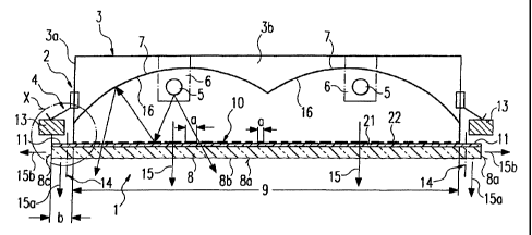
The main parts of the light identified overall by the
reference numeral 1, for example in the form of a built-
in light, are a base carrier 2 with a base member 3,
here in the shape of a frame or an inverted trough, on
which or on oppositely facing side walls 3a or on the
perimeter are provided distributed holding elements 4
for securing the light 1 on a light carrier, which
elements are mounted so that they can swivel outwardly
and inwardly and are preferably also mounted in a
CA 02430076 2003-05-27
WO 02/44612 PCT/EPO1/13753
11
height-adjustable manner (not shown). In addition the
light 1 comprises: one or more, for example two, light
sources 5 or lamps, for example gas-filled tubes,
arranged here in the interior of the base member 3,
which can be detachably mounted on the base member 3 by
means of plug-in sockets 6, a reflector 7 for the at
least one light source 5, and a panel 8, which in the
present embodiment is flat or of laminar design, with an
emission surface 8a on the broad side that is for
example larger than an emission opening 9 in the base
member 3 of the light 1 and thus covers not only the
emission opening 9, but also edge strips 11 at least on
oppositely facing edges of the base member 3.
In the present embodiment the edge strips 11 are formed
by edge arms lla projecting laterally from the free
edges of the side walls 3a, the free edges of the edge
arms 11a being able to be bent into edge arms lib facing
away from the panel 8, for the purposes of their
stabilisation. An edge region llc of the base member 3
is.formed in this way. The purpose of the edge
strips 11 is for example to cover an installation gap in
an installation opening in a ceiling 13 in which the
light 1 is installed as a built-in light, wherein the
edge strips 11 overlap the edge of the installation
opening and rest against the underneath of the
ceiling 13. The panel 8 is held in place on the base
member 3 by one or more laterally arranged detachable
retaining devices 14.
During operation of the light 1 equipped with
conventional operating means such as for example a
ballast and connection elements for at least one light
source 5 of the lamp, the light generated by the light
CA 02430076 2003-05-27
WO 02/44612 PCT/EP01/13753
12
source(s) 5 is emitted through the emission opening 9
and from the emission surface 8a into the space to be
illuminated. In order to illustrate this emitted light,
a resulting main light beam is in each case represented
as an arrow and identified by the reference numeral 15.
The light 1 and its emission opening 9 or its panel 8
may be oblong in shape, for example rectangular or
square. The shape may also be rectangular and oblong,
the side walls 3a and/or the edge strips 11 being
arranged on the long sides. Oppositely facing side
walls 3b that are joined to the side walls 3a and form
the already mentioned trough may also be present on for
example the narrower front sides. In such a case the
light 1 is an individual light, wherein the edge
strips 11 are also arranged on the two remaining sides,
here the narrower transverse sides, i.e. are arranged
peripherally.
The design shown in Fig. 1 may however also comprise a
row of lights consisting of a plurality of lights 1
arranged after one another, a light 1 with an end-side,
transversely running side wall 3b being arranged in each
case at the ends of the row, while the lights 1 arranged
between the end-side lights 1 have groove-shaped base
members 3 or troughs without transversely running side
walls 3b. In such a design the panels 8 arranged behind
one another along the row of lights may rest against one
another at associated gaps (not shown). The respective
base carriers 2 and reflectors 7 may also rest against
one another at the respective gaps. The installation
opening should be designed to be suitably long having
regard to the number of lights 1 arranged after one
another. A tubular lamp is particularly suitable for
CA 02430076 2003-05-27
WO 02/44612 PCT/EP01/13753
13
such a design or for an individual light, the light 1
also being able to have a longitudinally extended
structural shape.
The reflector or reflectors 7 consist in a known manner
of two oppositely facing and - viewed in the
longitudinal direction of the light 1 - concavely
rounded reflecting walls 16 or of a tunnel-shaped
reflecting wall 16, which in the present embodiment form
for example a so-called double light or multiple light,
in which the light source 5 and the reflector 7 are
double or multiple. The respective reflector 7 or a
common reflector 7 for several light sources 5 is
secured, preferably in a detachable manner, to the base
member 3, as is customary, for example by means of catch
devices (not shown), which permit a user-friendly and
quick installation and dismantling via the emission
opening 9.
The panel 8 consists of transparent material, for
example plastics or glass. In this connection the
panel 8 may be completely transparent or partially
transparent, or opal. The panel 8 may have a structure
8b, in particular a microstructure, preferably a
microprism structure, extending transversely to the main
direction of emission 15, for example arranged on its
outer emission surfaces 8a, or on its inner, light-
receiving surface, whereby glare from the light 1 is
suppressed and the light pattern at the emission
surface 8a has less contrast and becomes more brilliant.
The structure 8b may be a preferably regular two-
dimensional structure and may be formed for example by
tooth-shaped or pyramidal protuberances that may be
arranged, preferably in a profiled manner, in rows
CA 02430076 2003-05-27
WO '02/44612 PCT/EPO1/13753
14
running transverse to one another. Such a structure 8b
ensures a glare suppression since the light is emitted
only within a restricted angular range. An observer
viewing from the side is not subjected to glare. The
emission surface 8a may for example also be rough or
matte. The emission surface 8a may however also be
smooth. The microprism structure 8b may be arranged on
the outside or inside of the panel 8.
The flat or laminar panel 8 is also able to act as a
light guide so that the light passes not only
transversely through the panel 8, but in the panel 8
itself is also guided transversely to the main direction
of emission 15 into the edge regions covering the edge
strips 11, with the result that the light is also
emitted from the emission surface 8a in these regions.
The dark edge regions of the light 1 that exist iri the
prior art are thereby also avoided or at least reduced.
Alternatively the panel 8 may be produced from opal
white material, preferably pearl diffusing material, in
particular from PMMA.
Furthermore the panel 8 may also serve to illuminate the
surrounding peripheral region, for example the
surrounding ceiling region in the case of a ceiling
light. This is made possible by the fact that the
panel 8 also has on its perimeter or its perimeter
surface an emission surface 8c at which light is emitted
and contributes to the brightness of the surroundings of
the panel 8 or of the light 1. The light rays emitted
in the regions covering the edge strips 11 and the light
rays emitted in the perimeter region are identified by
15a, 15b.
CA 02430076 2003-05-27
WO 02/44612 PCT/EPO1/13753
The ability of the panel 8 to guide the light
transversely to the main direction of emission 15
increases with increasing thickness of the panel 8. It
5 has been found in tests that a ratio of the thickness a
of the panel 8 to the width b of the covered edge or
edge strips 11 of about 1:3 to 1:1, preferably about
1:2, is suitable. With a width b of about 12 mm the
resulting thickness a of the panel 8 is about 4 to
10 12 mm, in particular about 6 mm.
The panel 8 preferably consists of a clear plastics
material, in particular transparent PMMA, the panel
having microprisms at least on its emission surface 8a.
15 These microprisms are optimised in terms of lighting
technology and are formed by steep inclined surfaces
known per se of for example pyramids or studs, the
inclined surfaces forming an obtuse angle W of
preferably about 116.5 . This ensures that the light
glare is suppressed according to the lighting standard
(1000 cd/m2 under acute angles larger than 65 relative
to the mid-axis or direction of emission 15). Below
this value the light should emit ca. 4000 cd/mz. The
tips of the pyramids are spaced from one another.
Such a panel 8 may for example be about 3 mm to about
8 mm thick. The panel behaves in a highly efficient
manner on account of its thickness, especially in a
transparent modification.
Particularly in the case of a structured emission
surface 8a reflected light beams 15b emerge at the
lateral emission surfaces 8c, which are aligned
transverse to the direction of emission 15 or inclined
CA 02430076 2003-05-27
WO 02/44612 PCT/EP01/13753
16
to the side remote from the direction of emission 15.
This is particularly favourable for making the
surroundings brighter, especially with lights that are
installed in or on the ceiling.
The light 1 comprises light homogenisation means 10 in
the region of the light path between the light source 5
and the microstructure 8b. By means of the means 10 the
light coming directly from the at least one light
source 5 and/or reflected by the at least one reflector
7 can be influenced in such a way that, during operation
of=the light 1, the light intensity of the light
incident on the panel and thus also of the light emitted
at the emission surface 8a is substantially equal. The
means 10 may also be provided by means reducing the
passage of light in such a way that the degree of
reduction decreases with the distance from the light
source 5. Differences in brightness and light intensity
differences or contrasts in the region of the emission
surface 8a are thus avoided or at least reduced iri the
functional operation of the light 1. This is desirable
in order on the one hand to improve the illumination of
the space, and on the other hand to avoid or to reduce
visually recognisable light differences at the emission
surface, and thereby also to improve the appearance of
the light.
The means 10 may also be mounted on an inner panel
arranged between the light source 5 and the panel 8.
In the embodiment according to Fig. 1 a film 21 or an
inner panel is arranged between the light source 5 and
the panel 8, preferably resting on or against the
panel 8, and is held for example on the panel 8 or on
CA 02430076 2003-05-27
WO 02/44612 PCT/EPO1/13753
17
the base member 3 that comprise the means 10. The light
homogenisation may also be achieved in each case if the
film 21 or the panel is partially transparent in the
region of the shortest distance to the light source 5,
this transparency increasing with increasing distance
from the light source 5. The film 21 or the inner panel
may for example be opal or matted.
The means 10 may also be formed by providing the panel 8
or the film 21 with a grid or a layer or a covering 22
that homogenises the light intensity of the light
reaching the panel 8 or exhibits a degree of light
reduction that decreases with the distance from the
light source. The layer or the covering 22 or the grid
may for example be imprinted. If the layer or the
covering 22 is formed as a grid, the light distribution
may be achieved if the grid width a decreases with
increasing distance from the light source 5 or the
distances between the grid increase.
Preferably the layer or the covering 22, or the grid,
are partially reflecting, wherein the degree of partial
deflection decreases with increasing distance from the
light source 5 and may preferably become zero.
In the embodiment according to Fig. 2, in which
identical or comparable parts are provided with the same
reference numerals, the reflecting surface 7a of the
reflector 7 comprises the means 10, namely a scattering
structure 23, for example behind the light source 5. In
this design the light rays reflected at the reflecting
surface 7a are scattered. This leads to a smoothing out
of the light profile in the light pattern and thus to
the desired homogenisation of the light pattern. The
CA 02430076 2003-05-27
WO 02/44612 PCT/EPO1/13753
18
means 10 may also be realised by a shaping and/or by a
different degree of reflection at different parts of the
reflecting surface (7a) such that the light intensity of
the light reaching the panel 8 is substantially the
same. The reflecting surface of the grid may also be
formed in a corresponding way.
In the embodiment according to Fig. 3, in which
identical or comparable parts are also provided with the
same reference numerals, a flat or preferably curved
inner panel 24 forming the means 10 is formed as a
light-scattering panel between the light source 5 and
the panel 8, and scatters the light rays. The light-
scattering panel 24 may be opal and/or may comprise the
already described microstructure 8a, in particular the
pyramidal structure, on its side facing the panel 8. If
the microstructure 8b is present, the light-scattering
panel 24 may be transparent.
The modifications according to the invention are in each
case suitable in isolation as well as in combination for
improving, in the sense of a light homogenisation, the
light pattern produced at the emission surface 8a during
functional operation.
The panel 8 may also be formed as a diffuser panel and
may be matte or opal. This means that it contains very
small particles that scatter the light. The diffuser
panel therefore scatters incident light rays from the
lamp in all directions. An observer standing outside
the incident illumination region of the light thus has
the visual impression of scattered light. This is
desirable insofar as the diffuser panel ensures a
largely uniform light emission.
= CA 02430076 2003-05-27
WO 02/44612 PCT/EP01/13753
19
The combination of a panel 8 formed as a diffuser panel
with a light-scattering panel 24 having the
microstructure 8b reduces the brilliance of the light
pattern, which may be desirable.
An enhanced brilliance is obtained if the panel 8,
preferably structured with pyramids, is combined with a
grid or a light-scattering structure 23 at the
reflecting surface 7a or if this panel 8 is combined
with the light-scattering panel 24, for example omitting
the formation of the panel 8 as a diffuser panel,
wherein the panel 8 may for example be transparent.
The aforedescribed means 10 according to the invention
for the light distribution may be formed in addition or
only on the light-scattering panel 24, which latter may
then be appropriately made for example opal and/or
coated and/or covered and/or provided with a grid.
The designs according to the invention are ideally
suitable for a so-called light field, in which several
lights 1 are arranged in cascade formation in one or
more rows running adjacent or crosswise to one another.
All embodiments may involve lights that are designed as
a built-in light or as a mountable light.
The designs according to the invention are preferably
suitable for a flat light with a flat dome-shaped
reflector 7. In a flat light the distance between the
light source 5 and the panel 8 is particularly small and
accordingly the differences in the light intensity of
the light emitted from the panel 8 and the differences
CA 02430076 2003-05-27
WO 02/44612 PCT/EPO1/13753
in brightness during operation are particularly large,
and the problem of a varying light pattern thus becomes
particularly important.
5 The invention enables a light 1 with an installation
height of about 50 mm to be realised, the desired light
properties thereby being achieved. For such a low
installation height it is advantageous to use for the at
least one light source 5 fluorescent lamps of 16 mm
10 diameter, which preferably extend rectilinearly.
The designs according to the invention are also suitable
in an extremely advantageous manner for the embodiment
according to Fig. 4, in which a free space 31 is
15 arranged between the edge region 11c and the inside of
the panel 8, which free space extends up to a bearing
surface part 32 arranged on the edge of the panel 8 and
that is part of the carrying member 3. The free
space 31 is preferably formed so as to converge towards
20 the edge. In the embodiment it is bounded by the inside
of the panel 8 and by the outer surface, facing towards
it and preferably flat, of an edge arm lla. The
boundary surfaces form an acute angle W1 of about 15 to
about 30 , preferably about 23 . As already explained
in the aforedescribed embodiment, the edge arm lla and
the preferably also present edge arm 11b may be joined
as one part to a side wall arm 3a1 forming the
associated side wall 3a, for example may be bent away
from it.
On account of the presence of the free spaces 31 that
laterally face one another or are present over the whole
perimeter, the light emitted by the light source or
lamp 5 or reflected from the oppositely facing
CA 02430076 2003-05-27
WO 02/44612 PCT/EPOl/13753
21
reflecting wall 16 can penetrate directly substantially
up to the edge of the panel 8 into the latter, whereby
the external and/or lateral emission in the region of
the auxiliary light rays 15a and 15b is improved and
intensified. In this way light is increasingly emitted
in the region of the edge of the panel 8 and accordingly
the surroundings are increasingly illuminated, whereby
the contrast of the light 1 or panel 8 with respect to
the surroundings and to the central region of the
panel 8 is reduced.
Within the scope of the invention one or more retaining
devices 14 may be arranged on oppositely facing sides of
the light 1 inside the edge region llc, as shown in
Fig. 4. In this design the retaining elements
associated with the base member 3 may preferably be
detachably secured to the inside of the base member. In
the embodiment according to Fig. 4 the at least one
retaining device 14 is formed by a catch device 41 with
a catch pin 42 that can be engaged by a movement away
from the side facing the space to be illuminated
together with at least one catch element 43 arranged on
the base member 3. On account of at least one
spring-elastically effective catch element, this catch
device 41 is formed in such a way that when the catch
pin 42 is inserted the catch element 43 automatically
gives way and snaps into place. To release the catch
pin the catch device 41 can be overridden by a manual
tractive force on the catch pin 42, i.e. by exerting a
manually applicable tractive force on the catch pin 42
the catch element or elements 43 automatically give way,
with the result that the locking action is released and
the panel 8 can be removed from the base member 3. The
panel 8 can be installed by a user-friendly insertion of
CA 02430076 2003-05-27
WO 02/44612 PCT/EPO1/13753
22
the at least one catch pin 42, the at least one catch
element 43 automatically giving way and engaging with
the catch pin 42. The catch pin 42 protruding
internally from the panel 8 preferably consists of
transparent material and can engage the panel 8 in a
hole 44. A pinhead 45 that is optionally present
engages in a countersunk hole 44.
At least one small air gap should be arranged between
the inner panel or film 21 and the panel 8 in order not
to interfere with the light-conducting function of the
panel 8. The air gap is provided by an abutment surface
or bearing surface of the internal additional panel or
film 21.
In the embodiment according to Figs. 5 to 8 the light
identified overall by the reference numeral 51 is
likewise aligned towards the light emission in a main
direction of emission 52 in a first emission zone, which
in the situation according to Fig. 5 is aligned
vertically downwards. Also, in a lateral region B the
light 51 is aligned upwardly for a light emission in
order to illuminate the space over this lateral region B
or the ceiling space in the manner of an indirect
illumination. To this end the light 51 comprises a
preferably flat first transparent panel 54 that is pre-
arranged roughly in the centre and transverse to the
main direction of emission 52 of a light source 55. In
addition the light 51 comprises a preferably also flat
second transparent panel 56 that extends in the lateral
region B, likewise transverse to the main direction of
emission 52, but spaced laterally with respect to the
latter.
CA 02430076 2003-05-27
WO 02/44612 PCT/EPO1/13753
23
The panels 54, 56 are walls of a light source
housing 57, which according to Fig. 5 is in the shape of
a tunnel or dome, wherein the lateral region B is
arranged with respect to the main direction of emission
52 on one side, in Fig. 5 for example on the left-hand
side of the light 51 or of the light source housing 57,
and forms a ceiling wall section 58 of the tunnel-shaped
or dome-shaped light source housing 57. The ceiling
wall section facing the axis of the main direction of
emission 52 is identified by the reference numeral 59
and is formed by a reflector 61 that extends from the
central ridge region behind the light source 55
laterally as far as the edge region of the light source
housing 57 on this side. In the embodiment the ceiling
wall sections 58, 59 extend upwardly in a convergent
manner from the oppositely facing lower side edges
62, 63, and coincide in the ridge region, the tunnel-
shaped or dome-shaped contour thereby being formed. The
reflector 61 is as regards its reflecting surface 61a
curved concavely at least in the ridge region or over
its whole width. The curvature may be progressive up to
the ridge region in order to reflect the light rays
emitted from the light source 55 into the main direction
of emission, the resultant direction being identified by
the arrow 52. In the embodiment the ceiling wall
sections 58, 59 extend substantially from the lateral
edges 62, 63 of an associated floor wall section of the
light source housing 57, which is formed by the first
panel 54. The light source housing 57 thus has a
substantially triangular cross-sectional shape, whose
corner remote from the main direction of emission 52 may
be rounded in the ridge region.
CA 02430076 2005-07-18
24
In the embodiment the second panel 56 extends over the whole
lateral region B, in which connection it may start from the
associated side edge 62 and extend up to the facing edge of
the reflector 61. The external edges of the panels 54, 56
may be tightly connected at the side edge 62 to a side wall
section (not shown) of the light source housing 57. In the
case of the substantially triangular shape of the light
source housing 57 the panels 54, 56 extend as far as the
common corner region, where they may tightly abut one
another or are joined to one another, so that they are
formed by a prefabricatable one-piece panel structural part.
In the embodiment the second panel 56 arranged divergently
with respect to the first panel 54 forms an acute angle W2
with the said first panel 54, which may for example be about
15 to 60 and is preferably about 20 . The panels 54, 56
may in the region of the side edge 62 directly start from
one another or may be joined to one another by a rounded or
straight panel section 64. The one-piece panel structural
part may be directly formed in this shape, for example by
injection moulding or by bending about a common bending line
(not shown), or may be bent about two bending lines 65a, 65b
arranged above one another, for example in the heated state
at least in the region of the at least one bending line. On
the oppositely facing side edge 63 the reflector 61 extends
preferably as far as the associated edge of the first panel
54. The light source housing 57 described so far may be
closed by side walls 66, shown in Fig. 7, on the two
remaining oppositely facing sides, which in the embodiment
extend from the first panel 54 in the cross-sectional shape
of the light source housing 57 as far as the second panel 56
and up to the
CA 02430076 2003-05-27
WO 02/44612 PCT/EPO1/13753
reflector 61, and may be securely joined to the panels
54, 55, for example by a plug-in connection or by
bonding or welding. The side walls 66 may consist of
transparent or opaque material, and in the first case
5 may thus be involved in a lateral light emission.
Mechanical and electrical connection means for the light
source 55 are arranged in the light source housing 57,
and preferably comprise a gas discharge lamp, preferably
10 in the form of one or two tubes. The one or two
connection means arranged in oppositely facing end
regions of the light source housing 57 may be formed by
a conventional plug-in socket whose socket bodies 67 are
arranged in the ridge region and are secured internally
15 on the light source housing 57. In the embodiment two
electrical connection means are arranged adjacent to one
another for two tubular gas discharge lamps 68, in each
case on a common socket body 67. The light source
housing 57 is preferably designed lengthwise in the
20 longitudinal direction of the gas discharge lamps 68 so
that the width Bl shown in Fig. 5 is less than the
length L of the light source housing 57 shown in Fig. 6.
The light source housing 57 is rigidly or detachably
25 connected to a base carrier 71, by means of which or
with which it can be positioned jointly on a holding
device in the existing space. The base carrier 71 is
preferably arranged substantially in the spatial region
above the reflector 61, wherein the cross-sectional
shape of the base carrier 71 extends from the side
edge 63 as far as the apex region, preferably up to the
second panel 56, and expands the associated section of
the light source housing 57, in the present case roughly
into the right-hand half of the light source housing 57,
CA 02430076 2003-05-27
WO 02/44612 PCT/EP01/13753
26
to form a rectangularly shaped structural body. The
base carrier 71 is preferably a hollow box with a side
wall 73 extending upwardly from its side edge 63, from
the upper edge of which side wall there preferably
extends in one piece a ceiling wall 74 as far as the
apex region, preferably up to the second panel 56. In
order to stabilise this edge of the ceiling wall 74 an
upwardly extending arm 75 may be arranged on the edge,
and is preferably bent upwardly. In order to prevent
the arm 75 protruding beyond the upper side, the ceiling
wall 74 in the relevant edge region b may be bent
downwardly so that the arm 75 terminates roughly with
the upper side of the second panel 56. The edge region
of the reflector 61 facing the second panel 56 is
connected, preferably detachably, to the for example
downwardly bent ceiling wall 74, and can be screwed in
from the inside or outside in a space-saving manner by
for example a cap screw 76 engaging both parts in
matching holes, for example a so-called self-tapping
screw. The light source housing 57 is stabilised by the
abutment of this edge region of the reflector 61 on the
ceiling wall 47. In addition, in the ridge region the
reflector 61 may be supported via its inside on a
stepped surface 77 of the socket member 67 arranged in a
mirror-image manner. The opposite side edge of the
reflector 61 is detachably secured to the side wall 73
of the base carrier 71. On this side edge the reflector
61 may comprise an upwardly bent arm 78 that may serve
for the abutment or securement to the side wall 73.
This side edge of the reflector 61 is preferably
positioned on the base carrier 71 or on its side wall 73
by means of a plug-in socket 79.
CA 02430076 2003-05-27
WO 02/44612 PCT/EPO1/13753
27
Electrical connection and/or operating components for
the light 51 may be arranged in the free space 81 above
the reflector 61, for example an electrical ballast 82
that is joined or can be joined to a power supply cable,
which may pass through a passage in the side wall 73 or
ceiling wall 74 and is connected to at least one further
connection cable (not shown) together with the at least
one connection element 67a of the socket.
As can be seen from Figs. 7 and 8, the base carrier 71
may comprise two further side walls 83 extending from
the side wall 73 and the ceiling wall 74 up to the ridge
region, which contribute to the stabilisation and
laterally overlap the latter in its position connected
to the light source housing 57.
In order to connect the light source housing 57 to the
base carrier 71, a releasable connection is provided,
preferably in the form of a plug-in socket 84, into
which the light source housing 57 can be inserted by
means of a substantially horizontal movement, and which
can be prevented by securement means, preferably by
clamps, from coming loose. The plug-in socket 84 may
co-operate with the panels 54, 56. U-shaped clamping
elements 85, whose arms are clamping arms that engage
the panels 54, 56 with a clamping force, are preferably
arranged on the lower edge facing the first panel 54 and
on the upper edge of the base carrier 71 facing the
second panel. The clamping arms preferably comprise at
their free edges convergent rounded or inclined
insertion surfaces that facilitate the insertion of the
panels 54, 56, wherein the clamping arms are elastically
splayed and press against the broad sides of the panels
54, 56 in a clamping manner. The clamping elements 85
CA 02430076 2003-05-27
WO 02/44612 PCT/EPO1/13753
28
may be secured to the edges of the base carrier 71 in
the form of U-shaped bars or in the form of a plurality
of clamping pieces arranged in a distributed manner.
The plug-in socket 79 may be formed by the gusset-shaped
free space between the side wall 73 and the facing arm
of the clamping element 85. The lower edge of the
reflector 61 is positioned in an interlocking manner in
this free space, having regard to the rigidity of the
reflector 61.
A fork-like holder 86 with a holder base 87 and holding
arms 88 protruding horizontally therefrom, whose length
corresponds to the width Bl of the light 51, is provided
for the positioning of the light 51 formed by the light
source housing 57 and the base carrier 71 in the space
to be illuminated, so that the free space existing
between the holder arms 88 roughly corresponds to the
corresponding size of the light 51. The holder arms 88
may in their free end regions be matched on the upper
side to the shape of the light source housing 57, for
example may be suitably rounded or inclined. The
relevant inclined surfaces are identified by 89. To
retain the light 51 on the holder base 87, carrying
elements 91 are arranged at least on the mutually facing
sides of the holder arms 88 or also on the facing side
of the holder base 87. In the embodiment the carrying
arms 91 are arranged on the lower edge of these parts,
and may be formed by protruding carrying arms, which for
example are formed continuously on the associated edge
of the parts carrying them. A plug-in socket 92 is
thereby formed, into which the light 51 from a region
can be inserted horizontally to vertically. At least
CA 02430076 2003-05-27
WO 02/44612 PCT/EPO1/13753
29
one securement element (not shown) is provided in order
to secure the light 51 in the plug-in socket 92.
In the embodiment the light 51 and the holder 86 are
capable of being mounted on a support (not shown), for
example a wall of a room, or are capable of being
mounted on a ceiling in the suspended position. One or
more brackets or pendants may serve for this purpose,
which are connected or can be connected at one end to a
securement element for mounting on the ceiling and at
the other end to the holder 86, for which purpose
connecting elements 93 may be arranged on the holder 86,
in this case on the upper side of the holder base 87.
For a lateral securement, securement elements 94 may be
arranged on the rear side of the holder base 87, for
example for fastening screws for screwing into the
support, which may be accessed by lateral recesses (not
shown) in the holder base 87.
The holder base 87 and preferably also the holder
arms 88 may be box-shaped hollow bodies and may consist
for example of sheet metal. The holder base 87 may be a
so-called ceiling sail that projects from an air-
conditioning unit (not shown), wherein heating and
cooling ribs (not shown) through which liquid flows
extend along the holder base 87.
The first panel 54 may correspond as regards its design
and function to the panel 8 of the aforedescribed
embodiments. It may for example include on its lower
side or upper side a microstructure 8b to suppress
glare. Aforedescribed light homogenisation means 10 may
also be provided.
CA 02430076 2003-05-27
WO 02/44612 PCT/EPO1/13753
In the embodiment the panels 54, 56, 66 consist of
transparent material, for example glass or plastics, in
particular PMMA. A panel 8 that is for example
microstructured, in particular microprism-structured, on
5 the underneath or upper side is arranged on the first
panel 54, the length of the panel 8 corresponding to the
length L of the first panel 54 and its width being such
that, when resting on the first panel 54, it extends
from the side edge 63 as far as the opposite edge 62 or
10 extends into the region of the hollow valley of the one-
part panel body. A light homogenisation means 10 is
arranged in the region of the light path between the
light source 55 and the panel 8, which means may be
formed for example as a film 21 and may rest on the
15 panel 8.
A second inner panel 95 may be arranged interiorly of
the second panel 56, which scatters the light exiting to
provide indirect illumination, whose resultant direction
20 of emission is shown by the inclined, upwardly extending
arrow 96 in a second emission zone. This may be an opal
panel or one from which the light exits in a diffuse
manner. A diffuser-pearl panel 95 is provided in the
embodiment. The thickness of the panels 54, 56, 66, 95
25 may for example be about 3 mm. The thickness of the
panel 8 may correspond to that of the aforedescribed
embodiments.
In the last described embodiment, with panels 54, 94 and
30 56, 95 lying adjacent to or abutting one another, the
clamping elements 85 are sufficiently large so that
their arms overlap the present panels in the
aforedescribed way.
CA 02430076 2003-05-27
WO 02/44612 PCT/EPO1/13753
31
In the embodiment a web 97 projects outwardly from the
lower edge of the side wall 73, the free edge of the web
being able to be stabilised by an upwardly bent arm 98.
The web 97 and the arm 98 rest on the adjacent edge of
the holder base 87. An installation gap 99 between the
base carrier 71 and the light 51 and the holder 86 is
thereby formed, in which the power supply cable can run.