Note: Descriptions are shown in the official language in which they were submitted.
2000P21335W0 CA 02430217 2003-05-22
PCT/DE 01/04437
- 1 -
Description
Method for preventing chemical crosstalk in enzyme-
linked reactions, and associated arrangement
The invention relates to a method for preventing
chemical crosstalk in enzyme-linked reactions using a
microreaction array having at least two reaction
chambers for receiving substances which react
chemically or biochemically with other substances. In
addition, the invention also relates to an arrangement
for carrying out the method.
Combinatorial analysis and synthesis are nowadays in
increasingly widespread use for the development of new
active ingredients in the life sciences industry
(pharmaceuticals), food technology, agro technology
(crop science), in medical diagnostics and also to
solve a very wide range of objectives in general
biotechnology. To carry out these methods, what are
known as microtitration plate techniques with reaction
wells in an array structure are used, employing either
96 or even 384 wells for simultaneous reaction on an
array surface of, for example, approx. 12 x 8 cm2. The
density of these arrays will increase further in
future, which means that different types of chemical
reactions have to take place in reaction chambers
arranged ever closer together.
US 6,143,496 A has disclosed a PCR (Polymerase Chain
Reaction) method, in which, in an array having a
multiplicity of reaction chambers, individual reactions
take place next to one another at elevated
temperatures. In this array, there are suitable means
for isolating specimen chambers, which can also be
achieved, for example, by means of a displacement
liquid. In particular, it is important to reduce the
specimen volume or to prevent evaporation of water. The
same problem in connection with a PCR method is
2 0 0 0 P213 3 5W0 CA 02430217 2003-05-22
PCT/DE 01/04437
- la -
discussed in WO 01/34842 A2, which claims an earlier
priority but was not published before the priority date
of the present application.
The situation is in principle different with what are
known as DNA chips, as are known from various
publications. The situation is taken to extremes, for
example, with an array of different DNA probe molecules
which are arranged at a spacing of only a few tens of
micrometers and with a density of, for example, a few
hundred positions per few mm2 on a planar substrate,
known as the DNA chip. If molecules which can move
freely are involved in the analytical detection of, for
example, unknown DNA, chemical crosstalk occurs with
such dense arrays.
For a number of reasons, for example on account of the
high specificity and the low detection limit,
CA 02430217 2003-05-22
WO 02/41992 PCT/DE01/04437
- 2 -
biochemical analysis often uses enzyme-linked detection
methods. By way of example, what are known as ELISA
(Enzyme-Linked ImmunoSorbent Assay) tests are in
widespread use in medical diagnostics and in the
research sector. (Literature reference c.f. B. Alberts
et al. (eds.), Molekularbiologie der Zelle [Molecular
biology of the Cell] (1997), 3rd edition, page 216, VCH
Weinheim) . Methods using enzyme markers in a known
redox (re)cycling are also employed for applications in
the field of the DNA chip (A.v.d.Berg, P. Bergveld
(eds.) Proceedings of the TAS '94 Workshop (1994),
pp. 249 to 254, Kluwer Academic Publishers Dordrecht).
In all cases mentioned in the specialist literature,
the enzyme is not free in the liquid phase of the
arrangement, which is also known as an assay, but
rather is bonded and therefore, as an "enzyme label"
marks the primary substance to be detected. In this
case, the bonding of the enzyme molecules to the
substance to be detected is always stoichiometric.
Amplification occurs in that the enzyme converts added
substrate molecules at high speed. This conversion is
quantified, for example, optically or
electrochemically, depending on the substrate used
and/or the product formed. For this purpose,
irrespective of the method used, in particular the
increase in concentration of the product P, i.e. the
time-dependent function dc(P)/dt, is monitored.
If assays of this type are carried out in an array, as
described in detail in the prior art, reaction products
which can move freely and are formed by the enzyme can
also reach adjacent enzyme-free array positions, where
they may simulate the presence of the enzyme label.
This phenomenon is known as crosstalk, which leads to
measurement errors and may therefore give false
results.
Working on the basis of the above, it is an object of
CA 02430217 2003-05-22
WO 02/41992 PCT/DE01/04437
- 2a -
the invention to provide methods and associated
arrangements which, compared to the prior art, ensure
increased reliability by avoiding
CA 02430217 2009-03-13
20365-4737
- 3 -
crosstalk and thereby ruling out "false positive" results.
An increased accuracy is intended to produce improvements in
particular in the effectiveness of the measurements.
In one aspect, the invention relates to a method
for preventing chemical crosstalk in enzyme-linked detection
reactions, using a microreaction array with at least two
reaction chambers for receiving substances which chemically
or biochemically react with one another, comprising the
following measures: locally delimited reaction chambers are
used as a first volume, the reaction chambers are connected
to one another via a second volume, known as the supply
volume, enzyme-linked reactions take place in the individual
reaction chambers differentiated by species and/or
quantitatively, the mass transfer between reaction chambers
and the supply volume is permitted or prevented in one or
both directions as required, wherein the mass transfer is
prevented by a housing top part that closes off the reaction
chambers by means of a mechanical ram.
In another aspect, the invention relates to the
arrangement as described above, wherein the reaction
chambers have a volume of less than 1jil. Refinements of
the arrangement are given in the dependent device claims.
CA 02430217 2009-03-13
20365-4737
- 3a -
In the method according to the invention, locally
delimited reaction chambers are used as a first volume,
and the reaction chambers can be connected to one
another via a second volume, known as the supply
volume, and in the individual reaction chambers
chemical or biochemical reactions take place
differentiated by species and/or quantitatively.
Reactions differentiated by species are understood as
meaning qualitatively different processes. In this
case, equally, mass transfer between reaction chambers
and the supply volume is permitted or prevented in one
or both directions as required.
A significant advantage of the invention is that,
despite the fact that the reaction.chambers are closely
adjacent, disruptive crosstalk, which may distort the
measurement results, is rendered impossible, and the
selectivity is thereby improved. Moreover, the
invention also increases the detection sensitivity,
i.e. the detection limit is shifted toward smaller
quantities.
For practical realization of the detection sensitivity
increase, it is appropriate for the change in
substrate/product concentration over the course of time
to be increased as far as possible. In the method
according. to the invention, this is achieved by a
targeted reduction in the reaction volume to
significantly less than 1 m,
CA 02430217 2003-05-22
WO 02/41992 PCT/D801/04437
- 4 -
in particular to the region of 1 nanoliter (1 nl), and
an associated increase in the substrate product
concentration changes.
The arrangements according to the invention are in each
case arrays of more than two positions, and typically a
few hundred positions, on a few square millimeters,
preferably 1 to approx. 10 mm2, arranged on a planar
substrate. The array is in each case designed as an
array of reaction chambers or reaction spaces and
advantageously forms part of a vessel with a supply
volume which is jointly accessible to the reaction
chambers. A supply volume of this type can be produced,
for example, by embedding the reaction chamber array in
a flow cell, via which the overall fluid handling of
the chemical/biochemical substances required for the
detection or synthesis reaction can be performed.
In a first preferred embodiment of the invention, by
pressing a mechanical device onto the substrate, the
reaction chambers formed by the individual array
positions can be separated from one another by means of
an elastic membrane or layer which lies opposite the
planar substrate in the flow cell and may consist, for
example, of silicone rubber, so that crosstalk is
effectively prevented. A device of this type may, for
example, be in the form of a cover, a ram or a sealing
membrane, by means of which the cavities formed by the
reaction chambers are closed off. Closing off the
cavities also causes the volume of the liquid spaces
above the individual array positions to be reduced, so
that the change in concentration of the
substrate/product which is initiated by the
chemical/biochemical reactions is increased.
Consequently, therefore, the detection sensitivity is
also advantageously increased.
CA 02430217 2003-05-22
WO 02/41992 PCT/D}301/04437
- 5 -
In another preferred embodiment of the invention, the
same effect can be achieved by positioning a layer of
barrier liquid on top. As soon as a suitable barrier
liquid which cannot mix with the liquid in the reaction
cavities fills the flow channel, the same effects are
achieved as with the array cavities being closed up by
means of a silicone ram. The barrier liquid is, for
example, silicone oil. In an advantageous variant of
this embodiment, the reaction chambers are filled with
hydrogel, in order in this way to impart mechanical
stability to the water-containing reaction chambers
when the barrier liquid enters the flow channel. The
hydrogel used may, for example, be polyacrylamide,
which has the required properties with respect to
silicone oil.
In a refinement of the claimed method which is
independently inventive, it is also possible to make
use of different chemical solubility characteristics of
the substances and materials involved. In this
embodiment of the arrangement according to the
invention too, the reaction chambers are advantageously
filled with a hydrogel. Different solubility
characteristics between hydrogel reaction chamber and a
suitable liquid phase in the flow channel of the supply
volume ensures that reaction starting materials from
the liquid phase enter the hydrogel phase but reaction
products can no longer leave the hydrogel phase. An
example of a reaction starting product of this type is
the enzyme substrate.
Further details and advantages of the invention will
emerge from the following description of figures
illustrating exemplary embodiments with reference to
the drawing in conjunction with the patent claims. In
the figures:
Figure 1 diagrammatically depicts a measurement
structure according to the invention,
CA 02430217 2003-05-22
WO 02/41992 PCT/DE01/04437
- 5a -
illustrating the measuring method, on the one
hand, and the disruptive crosstalk, on the
other hand,
CA 02430217 2003-05-22
WO 02/41992 PCT/DE01/04437
- 6 -
Figure 2 diagrammatically depicts, in three substeps,
an example of an arrangement for mechanically
closing the cavities,
Figure 3 diagrammatically depicts, in the form of
three substeps, a corresponding arrangement
for closing the cavities by means of barrier
media, and
Figure 4 diagrammatically depicts, in the form of
three substeps, a third arrangement in which
the cavities are closed off by utilizing
different solubility characteristics of the
media involved.
In the figures, parts which are identical or have a
similar action are denoted by identical or
corresponding reference numerals. The figures are in
part described jointly in the text which follows.
In Figure 1, 1 denotes a substrate with a planar
surface which is formed, for example, by the
crystallographic surface of a silicon chip. An array of
optical/electrical detectors 2, 2', ... is produced on
the substrate 1 at array positions 8, 8', ... and can
be used to carry out bioanalytical tests using enzyme-
linked reactions, for which purpose probe molecules, on
the one hand, and analyte molecules, on the other hand,
are used. On the array position 8, 8', ... there are
different probe molecules 110, 120, ..., so that
different analyte molecules can be detected on each
specific array position.
In detail, in Figure 1, for a method for bioanalytical
testing, a first probe molecule is denoted by 110 at
array position 8 and a second probe molecule is denoted
by 120 at array position 8', an analyte molecule is
denoted by 200 and an enzyme label is denoted by 300.
By way of example, the probe molecule 110 reacts
CA 02430217 2003-05-22
WO 02/41992 PCT/DE01/04437
- 6a -
specifically with a complementary analyte module 200
and thereby immobilizes an enzyme label 300 in a
position-specific manner in the array. An enzyme
substrate 400 which is then added as starting material
is converted into a product 500 by the catalytic effect
of the enzyme label 300.
CA 02430217 2003-05-22
WO 02/41992 PCT/D801/04437
- 7 -
In Figure 1, therefore, the analyte molecule 200 can
react only with the probe molecule 110 but not with the
probe molecule 120. The increase/decrease in
substrate/product can be measured at each array
position 8 , 8' ,... of the wafer 1 with the aid of the
optical or electrical detector 2, 2', ... located
there. In particular electrical detectors have
metrological advantages.
In accordance with the prior art, it is endeavored to
keep the array positions 8, 8', ... and the distances
between them as small as possible. A problem in the
prior art is that what is known as chemical crosstalk
may occur between the individual positions 8, 8', ...
This means that either enzyme substrate 400, which has
been defined above as the starting material, or the
reaction product 500 may move from a first array
position 8 to a second array position 8'. If a
neighboring position is reached, a false signal is
generated, simulating a positive result. In practice,
this is also referred to as a "false positive" signal.
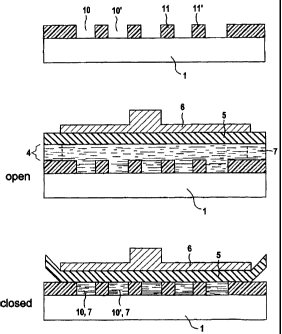
In Figures 2 to 4, for different alternatives
individual reaction chambers 10, 10', ... with an
individual volume of in each case less than 1 l are
arranged in an array configuration. The reaction
chambers 10, 10', ... are operationally separated from
one another.
Figure 2 illustrates three substeps describing the
actuation of an arrangement in which the reaction
chambers 10, 10', ... are separated by walls 11, 11',
... The walls 11, 11' can be produced in a particular
geometric embodiment by means of photopatterned,
circular polymer rings with an internal diameter of,
for example, 150 m, an external diameter of, for
example, 180 m and a height of, for example, 50 m.
The reaction chambers 10, 10', ... are filled, for
CA 02430217 2003-05-22
WO 02/41992 PCT/DE01/04437
- 7a -
example, with reaction starting material, e.g. an
enzyme substrate, dissolved in an electrolyte 7,
CA 02430217 2003-05-22
WO 02/41992 PCT/D801/04437
- 8 -
the electrolyte 2 being supplied to the individual
reaction chambers via a supply volume 4.
In Figure 2, the reaction chambers 10, 10', ... can be
closed off by a housing top part 5 by means of a
mechanical ram 6. In the open state, a supply volume 4
holding a liquid electrolyte is located above the
cavities. In Figure 2, the reaction spaces 10, 101,
..., as chambers which are open when the housing top
part 5 is removed, are filled with an
electrolyte/starting material 7 flowing through them,
the reservoir for the electrolyte 7 not being shown in
detail in this figure. After the reaction cavities 10,
10', ... have been filled with electrolyte/starting
material 7, the housing top part 5, which may comprise,
for example, a silicone membrane, is placed onto the
walls 11, 11', ..., which, as mentioned above, consist
of polyimide, by means of the ram 6. In this way, the
reaction spaces 10, 10', ... are closed off, so that
mass transfer is then prevented.
In Figure 3, the lower region is of similar
construction to that shown in Figure 2. In a particular
embodiment, which is not visible in the drawing
presented in Figure 3, the walls 11, 11', ... may be
specially produced by photopatterned, circular polymer
rings with an internal diameter d (d=2r) of, for
example, d=150 m, an external diameter of, for
example, D=180 m, a height h of, for example, h=5 m.
The reaction cavities which result from dimensions of
this type, with a filling volume of approximately
0.1 nl (r2nh = (75 m)2*3.14*5 m) are in this
particular embodiment filled with a hydrogel 3 with a
high capacity to take up water, e.g. polyacrylamide.
Then, a probe DNA for specific DNA detection can be
introduced in immobilized form into the hydrogel 3.
To carry out the assay, the reaction chambers 10, 10',
... are once again supplied with buffer, reagents and
CA 02430217 2003-05-22
WO 02/41992 PCT/DE01/04437
- 8a -
ultimately enzyme substrate via the common supply
volume 4. After the hydrogel 3 of each reaction chamber
10,
CA 02430217 2003-05-22
WO 02/41992 PCT/D801/04437
- 9 -
10' has been brought into equilibrium with buffer
containing enzyme substrate and the enzymatic
conversion has commenced, the supply volume 4 is
flooded with a barrier liquid, e.g. silicone oil. The
result of this is that the liquid above the reaction
chambers is displaced by silicone oil. The hydrogel
structure is responsible for the mechanical stability
of the reaction chambers. Since enzyme product is
insoluble in silicone oil, it is prevented from
diffusing out of the hydrogel toward neighboring
reaction chambers. Therefore, the reaction product can
increase greatly in the reaction chambers without
reaching the neighboring reaction chambers. Therefore,
high sensitivity and high selectivity are equally
present.
In both exemplary embodiments as shown in Figures 2 and
3, it is significant that the individual reaction
cavities 1 0 , 10' , . . . are first of all filled with the
electrolyte 7 passing through them from the supply
volume 4 and then a material, for example a silicone
oil 9, which forms phase boundaries with the
electrolyte 7, is applied. The phase boundary ensures
that mass transfer is then no longer possible and
disruptive distortions are prevented.
In the specific variant of the embodiment shown in
Figure 3, the reaction chambers 10, 10', ... are filled
with hydrogel 3, e.g. polyacrylamide, in order, in this
way to impart mechanical stability to the water-
containing reaction chambers 10, 10', ... when the
barrier liquid 9, e.g. silicone oil, enters the flow
channel.
In terms of its structure, Figure 4 once again
substantially corresponds to Figure 2. In a
corresponding way to Figure 2 and Figure 3, the
reaction chambers 10, 10' are filled from the supply
volume 4 by liquid passing through. In this case,
CA 02430217 2003-05-22
WO 02/41992 PCT/DS01/04437
- 9a -
however, the reaction starting materials, which are
denoted here by E, have the ability, on account of
their specific solubility characteristics, to penetrate
into the
CA 02430217 2003-05-22
WO 02/41992 PCT/D801/04437
- 10 -
electrolyte 7 located in the reaction chambers 10, 101,
... after they have been filled.
In the arrangement as shown in Figure 4, the reaction
in the reaction chambers then takes place in the same
way as has already been described above. On account of
the specific solubility characteristics of the reaction
product which forms and which is denoted here by P,
however, mass discharge of P is not possible in the
reaction. Therefore, the disruptive crosstalk is once
again prevented. In this embodiment, too, in a
corresponding way to Figure 3, the reaction chambers
are advantageously filled with a hydrogel 3.
The process described and the associated arrangements
can be used particularly successfully in medical
diagnostics and biotechnology. The prevention of
crosstalk as a significant source of errors which is
now achieved makes it possible to obtain more accurate
results than has hitherto been possible.
-1----------.