Note: Descriptions are shown in the official language in which they were submitted.
CA 02430357 2003-05-30
HYBRID POWER SUPPLY SYSTEM
This invention claims priority to prior Japanese patent application JP
2002-156757, the disclosure of which is incorporated herein by reference.
Bac_k~round of the Invention:
This invention relates to a hybrid power supply system comprising a load
(which is also operable as a power generator), an energy storage, a
bidirectional
DC/DC converter (that is, a bidirectional DC (Direct Current)-to-DC (Direct
Current) converter).
In recent years, attempts have increasingly been made to achieve a
hybrid power supply adaptable to drastic load variation and having a
regenerative energy recovery function by combining a secondary battery
capable of producing a stable output power and an electric double layer
capacitor excellent in large-current charge/discharge characteristics.
However,
merely by connecting the electric double layer capacitor and the secondary
battery, it is impossible to extract the energy stored in the electric double
layer
capacitor. In order to extract the energy, it is required to provide an
additional
circuit.
Referring to Fig. 1, a conventional power supply system having a
regenerative energy recovery function will be described. Fig. 2 shows a
circuit
diagram of the power supply system illustrated in Fig. 1. The power supply
system illustrated in Figs. 1 and 2 is disclosed in Japanese Unexamined Patent
Publication No. 2000-253503 (JP 2000-253503 A) as a regenerative energy
recovery apparatus for an electric vehicle. The power supply system comprises
a secondary battery 80 as an energy storage, an electric double layer
capacitor
CA 02430357 2003-05-30
2
10, and a DC/DC converter 112 inserted between the secondary battery 80 and
the electric double layer capacitor 10. In a normal running condition, a
motorlinverter 90 (which is operable as a load) is driven by the secondary
battery 80. In a braking condition, energy produced by the motor/inverter 90
(which serves as a power generator in this event) is stored in the electric
double
layer capacitor 10. The energy stored in the electric double layer capacitor
10
is supplied to the secondary battery 80 through the DC/DC converter 112 and a
rectifying element (diode) 111 to charge the secondary battery 80. With the
above-mentioned system, the energy recovery efficiency in the braking
condition
is improved.
However, the energy recovered as mentioned above is returned to the
secondary battery and then used. In a situation where the energy is used, for
example, during acceleration, the secondary battery discharges a large
current.
This results in rapid deterioration of the secondary battery and occurrence of
loss due to internal resistance.
In the above-mentioned power supply system comprising the secondary
battery, the electric double layer capacitor, and the motor as a power
generator,
it is most desirable to supply electric power to the motor as a load from the
secondary battery when stable electric power is required and from the electric
double layer capacitor when large electric power is required. In this manner,
it
is possible to fully exhibit respective characteristics of the secondary
battery and
the electric double layer capacitor. It is a major problem to establish a
system
capable of achieving such high-efficiency energy management.
The above also applies to a power supply system using an energy
storage other than the secondary battery. fn order to establish a power supply
system adaptable to drastic Toad variation and capable of providing stable
output
power, it is an important problem to achieve a hybrid system including the
energy
storage and the electric double layer capacitor.
CA 02430357 2003-05-30
3
A bidirectional DC-DC converter is disclosed in Japanese Unexamined
Patent Publication No. 2000-333445 (JP 2000-333445 A).
Another bidirectional DC/DC converter is disclosed as a bidirectional
step-up and step-down chopper circuit in Japanese Unexamined Patent
Publication No. 2001-268900 (JP 2001-268900 A).
~ummar~r of thg Invention:
It is an object of this invention to achieve a hybrid power supply system
capable of achieving high-efficiency energy management.
Hybrid power supply systems according to this invention are as follows:
1 ) A hybrid power supply system comprising: an electric double layer
capacitor (10) having a pair of capacitor terminals (11 and 12), an energy
storage (70a), and first and second bidirectionai DC/DC converters (30a and
30b), wherein the pair of capacitor terminals of the electric double layer
capacitor
are connected to a load (60a) through the first bidirectional DC/DC converter
and
are connected to the energy storage through the second bidirectional DC/DC
converter.
2) A hybrid power supply system as described in the above-mentioned
paragraph 1 ), wherein at least one of the first and the second bidirectional
DC/DC converters is a symmetrical DC/DC converter which comprises an
inductor (31 ) having a pair of inductor terminals and a pair of switching
portions
(32 and 33) connected to the pair of inductor terminals to be symmetrical with
each other with respect to the inductor, the symmetrical DC/DC converter being
operable as every one of a step-up converter and a step-down converter when a
particular one and a remaining one of the pair of switching portions serve as
an
input switch and an output switch, respectively, the symmetrical DC/DC
converter being also operable as every one of the step-up converter and the
step-down converter when the particular one and the remaining one of the pair
of
switching portions conversely serve as the output switch and the input switch,
CA 02430357 2003-05-30
4
respectively,
3) A hybrid power supply system as described in the above-mentioned
paragraph 1 ), wherein the load comprises a power generator (90).
4) A hybrid power supply system as described in the above-mentioned
paragraph 1 ), wherein the energy storage comprises a secondary battery (80).
5) A hybrid power supply system as described in the above-mentioned
paragraph 1), wherein the electric double layer capacitor comprises a
plurality of
electric double layer capacitors (10') connected in series, the system further
comprising a voltage balancing unit (20) for balancing respective voltages of
the
plurality of electric double layer capacitors connected in series.
6) A hybrid power supply system as described in the above-mentioned
paragraph 1), further comprising: an additional energy storage (70b) and an
additional bidirectional DC/DC converter (30b'), the pair of capacitor
terminals of
the electric double layer capacitor are also connected to the additional
energy
storage through the additional DC/DC converter.
7) A hybrid power supply system as described in the above-mentioned
paragraph 1), further comprising: an additional bidirectional DC/DC converter
(30a'), the pair of capacitor terminals of the electric double layer capacitor
are
also connected to an additional load (60b) through the additional DC/DC
converter.
Brief Description of the D~Wina~
Fig. 1 is a block diagram of a conventional power supply system having
a regenerative energy recovery function;
Fig. 2 is a circuit diagram of the power supply system illustrated in Fig. 1;
Fig. 3 is a block diagram of a hybrid power supply system according to a
first embodiment of this invention;
Fig. 4 is a circuit diagram of the hybrid power supply system illustrated in
Fig. 3;
CA 02430357 2003-05-30
Fig. 5 is a block diagram of a hybrid power supply system according to a
second embodiment of this invention;
Fig. 6 is a circuit diagram of the hybrid power supply system illustrated in
Fig. 5;
Fig. 7 is a block diagram of an electric double layer capacitor and a
voltage balancing unit which are used in the hybrid power supply system
illustrated in Fig. 5;
Fig. 8 is a block diagram of a hybrid power supply system according to a
third embodiment of this invention;
Fig. 9 is a circuit diagram of the hybrid power supply system illustrated in
Fig. 8;
Fig. 10 is a block diagram of a hybrid power supply system according to
a fourth embodiment of this invention;
Fig. 11 is a circuit diagram of the hybrid power supply system illustrated
in Fig. 10; and
Fig. 12 is a block diagram of a symmetrical DC/DC converter which may
be used as each of bidirectional DC/DC converters in the hybrid power supply
systems illustrated in Figs. 3, 4, 5, 6, 8, 9, 10, and 11.
Description of the Pr~ferr~.d Embodiments:
According to this invention which will presently be described, there is
provided a hybrid power supply system including an electric double layer
capacitor, an energy storage, and first and second bidirectional DCIDC
converters, the first bidirectional DC/DC converter connecting a laad and the
electric double layer capacitor, the second bidirectional DC/DC converter
connecting the energy storage and the electric double layer capacitor, the
hybrid
power supply system being operable in the manner such that the electric double
layer capacitor supplies energy to the load through the first bidirectional
DC/DC
converter to assist the energy storage when a larger current is required due
to
CA 02430357 2003-05-30
6
load variation and that, in a normal condition, the energy stored in the
electric
double layer capacitor is supplied to the energy storage through the second
bidirectional DC/DC converter to be stored in the energy storage. With this
structure, the hybrid power supply system is excellent in energy usability.
Preferably, at least one of the first and the second bidirectional DC/DC
converters is a symmetrical DC/DC converter which includes an inductor having
a pair of inductor terminals and a pair of switching portions connected to the
pair
of inductor terminals to be symmetrical with each other with respect to the
inductor. The symmetrical DC/DC converter is operable as every one of a
step-up converter and a step-down converter when a particular one and a
remaining one of the pair of switching portions serve as an input switch and
an
output switch, respectively. The symmetrical DC/DC converter is also operable
as every one of the step-up converter and the step-down converter when the
particular one and the remaining one of the pair of switching portions
conversely
serve as the output switch and the input switch, respectively. With this
structure, the hybrid power supply system is improved in degree of freedom in
design and high in versatility.
Preferably, in case where regenerative energy recovery is carried out by
using a load as a power generator, electric energy produced by the load is
supplied as regenerative energy to the electric double layer capacitor through
the first bidirectional DC/DC converter. With this structure, the hybrid power
supply system is improved in energy recovery rate and in energy usability.
Preferably, a secondary battery is used as the energy storage. With
this structure, the regenerative energy stored in the electric double layer
capacitor is efficiently supplied to the secondary battery through the second
bidirectional DC/DC converter. Thus, the hybrid power supply system is high in
versatility.
CA 02430357 2003-05-30
7
The hybrid power supply system may include a plurality of electric
double layer capacitors connected in series. In this case, the hybrid power
supply system further includes a low-loss voltage balancing (or equalizing)
apparatus for balancing (or equalizing) voltages of the electric double layer
capacitors. With this structure, the hybrid power supply system can utilize
the
performance of the electric double layer capacitor to the full extent.
According to this invention, there is also provided a hybrid power supply
system including an electric double layer capacitor, a plurality of energy
storages,
and a plurality of bidirectional DC/DC converters, the electric double layer
capacitor being connected to the energy storages through the bidirectional
DC/DC converters different from one another, respectively, and to a plurality
of
loads through the bidirectional DC/DC converters different from one another,
respectively. With this structure, it is possible to freely distribute the
amount of
energy to be stored in the energy storages and to freely distribute the energy
to
be used.
Now, hybrid power supply systems according to several embodiments of
this invention will be described with reference to the drawing.
First Embodiment
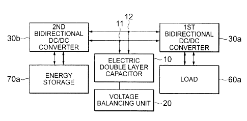
At first referring to Fig. 3, a hybrid power supply system according to a
first embodiment of this invention will be described. Fig. 4 shows a circuit
diagram of the hybrid power supply system illustrated in Fig. 3. In Figs. 3
and 4,
the hybrid power supply system is applied to a regenerative energy recovery
system of an electric vehicle. The hybrid power supply system includes an
electric double layer capacitor 10 having a pair of capacitor terminals 11 and
12,
first and second bidirectional DC/DC converters 30a and 30b, a secondary
battery 80 as an energy storage, and a motor/inverter 90 as a load. More
specifically, the pair of capacitor terminals 11 and 12 of the electric double
layer
capacitor 10 are connected to the motor/inverter (the load) 90 through the
first
CA 02430357 2003-05-30
8
bidirectional DC/DC converter 30a and are connected to the secondary battery
(the energy storage) 80 through the second bidirectional DC/DC converter 30b.
The first bidirectional DC/DC converter 30a controls the motor/inverter
90. At a start and during acceleration when a large current is required, the
second bidirectional DC/DC converter 30b controls an output power of the
electric double layer capacitor 10 and electric power is supplied from both of
the
electric double layer capacitor 10 and the secondary battery 80 to the
motor/inverter 90.
Hereinafter, the first bidirectional DC/DC converter 30a is defined as a
driving/regenerative bidirectional DC/DC converter while the second
bidirectional DC/DC converter 30b is defined as a charging/discharging
bidirectional DC/DC converter.
During deceleration, the motor/inverter 90 is used as a power generator.
Electric energy produced by the motor/inverter 90 is converted by the first
bidirectional DC/DC converter 30a into electric energy having a voltage
corresponding to the specification of the electric double layer capacitor 10.
Then, the electric energy is charged to the electric double layer capacitor
10.
On the other hand, in a normal running condition, the energy is supplied from
the
secondary battery 80 to the motor/inverter 90. 1n case where the energy in the
secondary battery 80 is decreased to some extent, the electric double layer
capacitor 10 charges the secondary battery 80 through the second bidirectional
DC/DC converter 30b. In case where the energy in the electric double layer
capacitor 10 is decreased, the secondary battery 80 supplies supplemental
energy to the electric double Payer capacitor 10 through the second
bidirectional
DC/DC converter 30b.
With this structure, it is possible to freely transfer any desired amount of
energy among the secondary battery, the capacitor, and the motor from a
desired one to another, irrespective of a voltage level of each of these
devices.
CA 02430357 2003-05-30
9
Second Embodiment
Referring to Fig. 5, a hybrid power supply system according to a second
embodiment of this invention includes an energy storage 70a and a load 60a.
The hybrid power supply system further includes a voltage balancing unit 20.
Fig. 6 shows a circuit diagram of the hybrid power supply system illustrated
in
Fig. 5.
Referring to Fig. 7, illustration is made of a combination of the electric
double layer capacitor 10 and the voltage balancing unit 20 which are used in
the hybrid power supply system illustrated in Figs. 5 and 6.
In Figs. 5, 6, and 7, the electric double layer capacitor 10 includes a
plurality of electric double layer capacitors 10' connected in series and in
parallel.
The voltage balancing unit 20 is for balancing respective voltages of the
plurality
of electric double layer capacitors connected in series and in parallel.
Inasmuch as the electric double layer capacitors 10', which are
connected in series in the manner illustrated in Fig. 7, are different in self-
discharge characteristic from one another, voltages gradually become
nonuniform and the energy density of the electric double layer capacitor 10 is
lowered when charging/discharging operations are repeated. Therefore, in
order to maintain the energy density of the electric double layer capacitor
10, the
voltage balancing unit 20 is operated at an appropriate timing to level the
voltages of the electric double layer capacitors 10'. The voltage balancing
can
be carried out in various manners, for example, by the use of a constant
voltage
element such as a Zener diode, by switching series-parallel connection, and by
transferring the energy between the electric double layer capacitors (see
Japanese Unexamined Patent Publication No. 2001-136660 (JP 2001-136660
A) and see EP1198050A1).
CA 02430357 2003-05-30
Third Embodiment
Referring to Fig. 8, a hybrid power supply system according to a third
embodiment of this invention includes first and second energy storages 70a and
70b connected to the electric double layer capacitor 10 through a primary
second bidirectional DC/DC converter 30b and a secondary second bidirectional
DC/DC converter 30b', respectively. Fig. 9 shows a circuit diagram of the
hybrid power supply system illustrated in Fig. 8. In Figs. 8 and 9, the
primary
and the secondary bidirectional DC/DC converters 30b and 30b' may be of the
same type or different from each other. The number of the energy storages
may be any desired number.
Fourth Embodiment
Referring to Fig. 10, a hybrid power supply system according to a fourth
embodiment of this invention includes a plurality of loads 60a and 60b
connected
to the electric double layer capacitor 10 through a primary first
bidirectional
DC/DC converter 30a and a secondary first bidirectional DC/DC converter 30a',
respectively. Fig. 11 shows a circuit diagram of the hybrid power supply
system
illustrated in Fig. 10. In Figs. 11 and 12, the loads 60a and 60b connected to
the
electric double layer capacitor 10 may be of the same type or different from
each
other. The number of the loads may be any desired number. Generally, the
energy storage is not restricted to the secondary battery but may be any
device,
such as a fly wheel, which can be charged and discharged. Similarly, the load
is not restricted to the motor but may be of any type.
As each of the bidirectional DC/DC converters 30a, 30a', 30b, and
30b'illustrated in Figs. Figs. 3, 4, 5, 6, 8, 9, 10, and 11, use may be made
of a
symmetrical DC/DC converter which is a bidirectional DC/DC converter capable
of freely controlling voltage step-up and step-down operations and which is
illustrated in Fig. 12.
CA 02430357 2003-05-30
11
The symmetrical DC/DC converter is proposed in Japanese Patent
Application No. 2001-369532 (Date of filing: December 4, 2001) and is
disclosed
in Japanese Unexamined Patent Publication No. 2002-238250 (JP 2002-238250
A) (Date of publication: August 23, 2002). The symmetrical DC/DC converter is
also disclosed in EP 1211791 A1 (Date of publication: June 5, 2002) (Date of
filing: December 4, 2001 ).
In Fig. 12, the symmetrical DC/DC converter includes an inductor 31
having a pair of inductor terminals and a pair of switching portions 32 and 33
connected to the pair of inductor terminals to be symmetrical with each other
with respect to the inductor 31. The symmetrical DC/DC converter is operable
as every one of a step-up converter and a step-down converter when a
particular
one and a remaining one of the pair of switching portions 32 and 33 serve as
an
input switch and an output switch, respectively. The symmetrical DC/DC
converter is also operable as every one of the step-up converter and the step-
down converter when the particular one and the remaining one of the pair of
switching portions 32 and 33 conversely serve as the output switch and the
input
switch, respectively,
More specifically, the symmetrical DC/DC converter includes the
inductor 31, first and second switching portions 35 and 36 having one ends
connected to one end of the inductor 31, third and fourth switching portions
37
and 38 having one ends connected to the other end of the inductor 31, first
through fourth terminals T1, T2, T3, and T4 connected to the other ends of the
first through the fourth switching portions 35, 36, 37, and 38, respectively,
and a
pair of capacitors 34 connected between the first and the second terminals T1
and T2 and between the third and the fourth terminals T3 and T4, respectively.
The second and the fourth terminals T2 and T4 are connected to each other.
Table 1 shows the states of the first through the fourth switching portions
35, 36, 37, and 38 in case where the first and the second terminals T1 and T2
CA 02430357 2003-05-30
12
are used as input terminals while the third and the fourth terminals T3 and T4
are
used as output terminals and in case where the first and the second terminals
T1
and T2 are used as output terminals while the third and the fourth terminals
T3
and T4 are used as input terminals. For each case, the step-up operation and
the step-down operation are shown.
Table 1
1 st, 2nd 3rd, 4th 35 36 37 38
Terminals _ Terminals
I O Ste -u~ ON OFF D SW
t t
t
npu u
pu
Ste -down SW D ON OFF
O i Ste -a D SW ON OFF
t t
t
u npu
pu
Ste -down ON OFF SW D
In Table 1, "ON" and "OFF" represent a short-circuited or a closed state
and an opened state, respectively. "SW" is a controlled state where ON/OFF is
intermittently switched under PWM control or the like so that an appropriate
step-up or a step-down ratio is obtained. "D" represents a rectifying state of
performing a rectifying operation.
Thus, the symmetrical DC/DC converter is operable as every one of the
step-up converter and the step-down converter when a particular one and a
remaining one of the pair of switching portions 32 and 33 serve as the input
switch and the output switch, respectively. The symmetrical DC/DC converter
is also operable as every one of the step-up converter and the step-down
converter when the particular one and the remaining one of the pair of
switching
portions 32 and 33 conversely serve as the output switch and the input switch,
respectively,
By the use of the symmetrical DC/DC converter which is a bidirectional
DC/DC converter capable of freely controlling voltage step-up and step-down
operations and which is illustrated in Fig. 12, the electric double layer
capacitor
more efficiently absorbs the energy and the energy can be extracted at a
CA 02430357 2003-05-30
13
desired voltage during discharging. Thus, it is possible to improve the degree
of freedom in design of the hybrid power supply system and the versatility.
For example, it is assumed that the hybrid power supply system of this
invention is applied to a hybrid vehicle. In the past, the scale or the
capacity of
the secondary battery is determined in dependence upon the maximum output
power of the motor. According to this invention, the electric double layer
capacitor can provide the supplemental energy required for the maximum output
power of the motor. As a consequence, it is sufficient for the secondary
battery
to provide the energy required for electrical components and normal running.
Therefore, it is possible to achieve the performance equivalent or superior to
that
presently attained and to reduce the size. Therefore, not only the energy
usability but also the transportation efficiency is improved. Since large
current
charging/discharging operations are carried out by the electric double layer
capacitor, the secondary battery as the energy storage is extended in
lifetime.
According to this invention, it is possible to establish a hybrid power
supply system small in size, light in weight, long in lifetime, and high in
energy
usability and having a performance substantially equivalent to that of the
conventional power supply system. If the hybrid power supply system of this
invention is applied to a transportation equipment such as an electric
vehicle, the
transportation efficiency is considerably improved.