Note: Descriptions are shown in the official language in which they were submitted.
CA 02430360 2003-05-29
EYEWEAR AND SYSTEM
FIELD OF THE INVENTION
The present invention relates to eyewear and particularly, to a system of
eyewear
having a number of different features including adjustable arms and
interchangeable lenses.
BACKGROUND OF THE INVENTION
Conventional eyewear, such as sunglasses, have a number of drawbacks. For
example,
the arms are typically a single moulded piece that is not easily adjustable. A
conventional ear
support for a pair of eyeglasses is formed as a one-piece ear stem, the length
of which is fixed.
If the length of the ear support is not proper, one might feel uncomfortable
v~aring the
eyeglasses. Particularly, a smaller length can cause aching of the
user°s ears, while a longer
length can hinder the lens frame from being properly seated on the user's
nose. Furthermore,
lenses are typically mounted in a fashion that makes it difficult to change
them. Although
conventional sunglasses may be suitable for use at the beach, they may not be
suitable for all
events, such as social occasions.
Accordingly, it is desirable to be able to modify eyewear to suit different
environments. To do so conveniently requires that fragile or delicate
components such as
lenses be readily available for use when desired and protected and accessible
when stored.
Furthermore, existing mechanisms for changing lenses can be awkward due to
relatively large
forces required to remove locking mechanisms. The small size of the parts
involved can also
make it difficult for the user maintain the necessary grip to perform the lens
changing
operation comfortably.
SUMMARY OF THE INVENTION
It is an object of the present invention to obviate or mitigate at least one
problem
associated with the prior art.
According to an aspect of the present invention, an eyewear system, includes:
at Least
one pair of lenses; an eyewear frame including a pair of lens frames, the lens
frames
connected by a bridge, each lens frame releasabiy holding a corresponding lens
of the at least
one pair of lenses; a locking element for clamping the bridge of the eyewear
frame and
CA 02430360 2003-05-29
z
preventing the lens frames from releasing the held lenses; the locking element
having a "C"
shaped cross-section, the locking element including a planar main portion, an
upper portion
relatively proximate to the nosepiece of the eyewear and a lower portion
relatively distant
from the nosepiece, the upper and lower portions attached at substantially
right angles to the
main portion, a descending upper flange attached to the uppex portion and a
rising lower
flange attached to the lower portion, and a tab provided on the rising lower
flange, the tab
protruding from the plane of the rising lowex flange and extending away from
the main
portion, the tab serving as a grip for manual manipulation of the locking
element by the user
and serving as a lever when removing the locking ele~nant from the eyewear
frame by rotating
the locking element about the upper portion; at Least one side support for
holding the eyewear
frame to a head of the user; releasable mounting means fox mounting the at
least one side
support to the eyewear frame; and a nosepiece mounted to the frame for spacing
the eyewear
frame from a face of the user.
In order to organize and store the components of an eyewear system, it is
desirable to
have a carrying case capable of protecting the components of the system while
not in use yet
compact enough to allow it to be easily carried by the user. In addition, the
system includes
different lenses for use in different environments or while performing
different activities. For
example, Light Equalization System lenses can be used to eliminate up to 100%
of harmful
W-A and LJV-B light rays. They self calibrate light frequencies to provide a
crisp contrast
and sharp definition. The top surface hard coat is scratch resistant. By
contxast the limiter
lenses are very dark lenses for exceptionally sunny days. The enhancer lenses
are high-
contrast lenses for dull, cloudy or hazy days.
To allow fox easier removal of side supports, namely the microslot arms, sport
arms or
headband from the eyewear frame and replacement of another one, an "S" shaped
complementary coupling member is provided on the side supports having planar
sidewalk for
engagement with a corresponding hollow in coupling members attached to the
eyewear frame.
The smooth featureless sidewalk of the complementary coupling member allows
easier removal of side supports compared with the prior art which included a
retaining
shoulder or other locking mechanisms which made it difficult to remove side
supports.
CA 02430360 2003-05-29
3
Advantageously, the eyewear system is more accessible, better organized and
more
portable due to the inclusion of the carrying case. The delicate items such as
lenses are
securely stored safe from scratches and breakage. Furthermore, changing the
lenses is greatly
facilitated by use of the tab on the vise lock lens transfer element.
BRIEF DESCRIPTI~N OF THE DRAWINGS
The features and advantages of the present invention will be described in more
detail
with reference to the accompanying drawings which illustrate the preferred
embodiments of
this invention, wherein:
Fig. 1 is an exploded perspective view of a pair of eyeglasses in the first
embodiment
of this invention;
Fig. 2 is an assembled perspective view of the eyeglasses in Fig. l, with an
impact
cushioning band detached from the lens frame;
Fig. 3a is a front plan view of the eyeglasses i.n Fig. 2 with the impact
cushioning band
removed therefrom for clarity;
Fig. 3b is a side view of the eyeglasses shown in Fig. 3a;
Fig. 4a is a partly schematic cross-sectional view taken along line B-B of
Fig. 3a,
where the lens receiving spaces are in a smaller-sized contracted state;
Fig. 4b is a view similar to Fig. 4a except that the lens receiving spaces are
in a large
sized normal state;
Fig. 5a is a partly schematic cross~ectional view taken along line A-A of Fig.
3a;
Fig. 5b is an exploded view of Fig. 5a;
Fig. 6 is a is a perspective view of a coupling member mounted on the right
side of
the lens frame; Fig. 6b is a bottom view of the coupling member shown in Fig.
6a;
Fig. 7a is a partly schematic cross-sectional view taken along line C-C of
Fig. 3a,
showing the engagement between the coupling member and the respective one of
the lens
retaining rims 10 at a section where a proj ection is provided;
Fig. 7b is a partly schematic cross-sectional view taken along line D-D of
Fig. 3a,
showing the engagement between the coupling member and the respective lens
retaining rim;
CA 02430360 2003-05-29
4
Figs. 8a and 8b illustrate the "S" lock complementary coupling member
according to
the present invention;
Fig. 9 is a perspective view of the right side ear stem;
Fig, 10a is an assembled schematic side view of an ear stem and an earpiece;
Fig. lOb is a view similar to Fig.10a, but with the earpiece being shown in
cross
section;
Figs. 1 la and 1 1b are perspective views of an earpiece and Fig. llc is a
rear view of the
earpiece;
Figs. 12a and 12b are cross-sectional views taken along lines E-E and F-F in
Fig.10a,
respectively;
Fig. 13 is a partly schematic side view of an earpiece and an ear stem,
showing the
earpiece in a position for adjustment;
Fig. 14 is a perspective view of the eyeglasses of this invention, wherein the
first stem-
type side support is replaced by the second strap type side support;
Figs. 15a and 15b are perspective views of a right side strap fastener of the
second
strap- type side support;
Fig 16a is a top view of a lens;
Fig. 16b is a partly schematic cross-sectional view showing the engagement
between
one of the lenses and the respective one of the lens retaining rims;
Fig. 17 is a perspective view of a cushioning band;
Fig. 18 is a front plan view of a pair of eyeglasses in a second embodiment of
this
invention, where a cushioning band is removed for clarity;
Fig. 19 is a partly schematic cross-sectional view taken along line G-G in
Fig. 18;
Fig. 20 is a perspective view of a carrying case according to another aspect
of the
present invention;
Fig. 21 is a plan view of the carrying case of Fig. 20;
Fig 22 is a front elevation view of the carrying case of Fig. 20;
Fig 23 is a right side elevation view of the carrying case of Fig. 20;
Fig 24 is a left side elevation view of the carrying case of Fig. 20;
CA 02430360 2003-05-29
Figs. 25a, 25b and 25c illustrate front, side and bottom views of a vise-lock
lens
transfer element according to the present invention;
Figs 26a, 26b and 26c illustrate front, bottom and enlarged views of a lens
adaptor
included in the present invention;
Figs. 27 to 36 illustrate changing the lenses of the present invention;
Figs. 37 to 42 illustrate changing the arm and headband of the present
invention;
Figs. 43 to 46 illustrate adjusting the microslot arms;
Figs. 47 to 49 illustrate installing the sport visor;
Fig. 50 illustrates cleaning the lenses;
Figs. 51 to 52 illustrate installing the optical adaptor;
Figs. 53 and 54 illustrate the attachment of the optical adaptor to the
eyewear in
sectional view; and
Figs. 55 and 56 illustrate the attachment of the optical adaptor to the
eyewear.
DETAILED DESCRIPTI~loT
Generally, the present invention relates to a system of eyewear having
numerous
features and advantages' as described below and illustrated in the drawings.
Referring to Figs. 1 to 3, a pair of eyeglasses 1 of a first preferred
embodiment of this is
shown to include a lens frame 2, a pair of lenses 4 mounted onto the lens
frame 2, and a side
support including a first side support G and a second side support 8 (see Fig.
14) The first side
support b is of a type that includes a pair of ear stems as shown in Fig 2,
while the second side
support 8 is of a type that includes a strap, as shown in Fig. 14. The first
side support 6 and
the second side support B are interchangeable to meet different needs.
The lens frame 2 which is formed integrally and made from a resilient
material, such
as plastic or polycarbonate, has a pair of lens retaining rims 10 that are
spaced apart in a first
direction on a plane of the lens frame 2. Each of the lens retaining rims 10
has an inner lateral
rim portion 12, an outer lateral rim portion 14, and an upper rim portion 18
connecting the
lateral rim portions 12, 14. The inner lateral rim portions 12 of the lens
retaining rims 10 are
disposed adjacent to each other. A bridge 20 extends in the first direction
and interconnects
the inner lateral rim portions 12 of the lens retaining rims. Preferably, the
front side ~f 2 the
CA 02430360 2003-05-29
6
bridge 20 is recessed with respect to front sides of the lens retaining rims
10. Each of the lens
retaining rims 10 further has a lens engaging inner periphery that confines a
lens receiving
space for receiving one of the lenses 4 therein.
A lens removing slit 22 is formed to communicate the two lens receiving spaces
formed by the lens retaining rims 10. The lens removing slit 22 eAtends iiom
the lens
engaging inner periphery of one of the lens retaining rims 10, through the
inner lateral rim
portion 12 of said one of the lens retaining rims 10 through the bridge 20,
ald through the
inner lateral rim portion 12 and the lens engaging inner periphery of the
other one of the lens
retaining rims I0. The lens removing slit 22 divides each of the inner lateral
rim portions 12
into an upper and a lower section 13, 15, and divides the bridge 20 into an
upper and a lower
section 20a, 20b. The upper section 13 and the Lower section 15 of each of the
inner lateral
rim portions 12, and the upper section 20a and the lower section 20b of the
bridge 20 are
normally spaced apart in a second direction transverse to the first direction.
The lens receiving spaces formed in the lens retaining rims 10 suitably
contain the
lenses 4 therein such that the lens engaging inner 2 periphery of each of the
lens retaining
rims 10 engages fittingly the outer periphery the respective one of the lenses
4. The lens
receiving spaces can be adjusted by forcing the upper section 20a and the
lower section 20b of
the bridge 20, as well as the upper sections 13 and the lower sections 15 of
the inner lateral
rim portions 12 toward each other so as to change the lens receiving spaces
from a larger-
sized normal state to a smaller-sized contracted state.
In the larger-sized normal state where the Lens receiving spaces are Larger in
size than
the lenses 4 to be inserted, the lenses 4 can be inserted easily into the lens
receiving spaces
and engage the periphery of a respective one of the lens retaining rims 10.
Once the lenses 4
are retained in position, the upper section 20a and the lower section 20b of
the bridge 20 and
the upper sections 13 and the lower sections I5 of the inner lateral rim
portions 12 are forced
together so as to change the lens receiving spaces into the smaller-sized
contracted state,
where the lenses 4 are firmly clamped by the inner periphery of the respective
one of the lens
retaining rims I0.
Referring to Figs. 4a and 4b, in the larger-sized normal state, the upper and
lower
sections 13, 15 of the inner lateral rim portions 12 are spaced apart by the
lens removing slit
CA 02430360 2003-05-29
7
22. The upper and lower sections 13, 15 of the inner Lateral rim portions IZ
have confronting
surfaces which are preferably formed with complementary abutment projections
13a and 1 a,
respectively that are staggered relative to each other in a third direction
transverse to thefirst
and second directions. When the upper and Lower sections 13, 15 are brought
into contact to
change the lens receiving spaces into the smaller-sized contracted state, the
confronting
surfaces of the upper and lower sections 13,15 abut fittingly against each
other in the third
direction.
Referring to Figs. 5a and Sb, the upper and lower sections 20a, 20b of the
bridge 20
are shown in an assembled and an exploded view, respectively. A.s with the
upper and lower
sections 13, 15 of the inner lateral rim portions 12, the upper and lower
sections 20a, 20b also
have confronting surfaces which are preferably formed with complementary
abutment
projections 23, 24. However, the complementary abutment projections 23, 24 of
the bridge 20
are not provided at the same side as the abutment projections 13a,15a of the
inner lateral rims
12. More specifically, the abutment projections 13a of the upper sections 13
are at the right
side as viewed in Figs. 4a and 4b, while the abutment projection 23 of the
upper section 20a
of the bridge 20 is at the left side thereof, as viewed in Figs. 5a and Sb.
Accordingly, the
abutment projections 15a of the lower sections 15 are at the left side
thereof, as viewed in
Figs. 4a and 4b, while the projection 24 of the lower section 20b of the
bridge 20 is formed at
the right side thereof. With such an arrangement, the shearing which occurs
between the
confronting surfaces of the upper and lower sections 13, 15 will be strictly
prevented. For
instance, the movement of an upper section 20a of the bridge 20 ~by a shearing
force applied in
the direction normal to the lenses 4 will be constrained by either the lower
section 20b of the
bridge 20 or by the lower section 15 of the inner lateral rim portions 12,
depending on which
direction the shearing force is applied.
To bring the upper and lower sections 20&, 20b of the bridge 20 and the upper
and
lower sections 13,15 of the inner lateral rim portions 12 into contact, a
fastener 25 is mounted
onto the bridge 20 for flanking the upper and lows sections 20a, 20b of the
bridge 20 and for
clamping the same together. As shown in Figs. 5a and Sb, the fastener 25
includes a front
plate portion 26 to be disposed on a front side of the bridge 20, an upper
hooking portion 27
extending rearwardly from a top edge of the front plate portion 26 for hooking
with the bridge
CA 02430360 2003-05-29
8
20 at a rear side of the upper section 20a of the bridge 20, and a lower
hooking portion
extending rearwardly from a bottom edge of the front plate portion 26 for
hooking with the
bridge 20 at a rear Bide of the lower section 20b of the bridge 20. The upper
and lower
hooking portions 27, 28 flank the upper and lower section 20a, 20b of the
bridge 20
thereberiveen. The upper hooking portion 27 has a bent distal end that extends
downwardly,
and the lower hooking portion 28 has a bent distal end that extends upwardly.
The lower section 20b of the bridge 20 has a tapering lower part f~rmed with
inclined
front and rear guide surfaces to guide engagement and disengagement between
the lower
hooking portion 28 and the lower section 20b of the bridge 20.
Preferably, the fastener 25 is formed integrally from a resilient material,
such as
polycarbonate or nylon zytel, to facilitate the mounting of the fastener 25
onto the bridge 20.
Further, as shown in Fig. 2, since the front side of the bridge 20 is recessed
with respect to the
front sides of the lens retaining rims I0, when the fastener 25 is mounted on
the bridge 20, the
front plate portion 26 of the fastener 25 is substantially flush with the
front sides of the lens
retaining rims 10 to provide an integral appearance.
A pair of hollow engaging parts is provided on the lens receiving rims 10 for
connecting the first side support 6 onto the Iens receiving rims 10. In this
embodiment, the
hollow engaging parts are formed on a pair of coupling members 30 which can be
mounted
detachably on the upper rim portions I 8 of the lens retaining rims 10. As
shown in Figs. 6a
and 6b, each of the hollow engaging parts 3I of the coupling members 30
extends rearwaidly
to confine an engaging space 32. An opening 32a is formed in each of the
engaging parts 31
to provide an access to the engaging space 32. Each of the hollow engaging
parts 31 is
disposed adjacent to the outer lateral rim portion 14 of the respective one of
the lens retaining
rims 10 for connecting with the first side support 6.
As clearly shown in Figs. 6a and 6b, each of the coupling members 30 further
has a
hollow mounting part 31a which has an open bottom side formed with at Ieast
one projection
31b. Refernng to Fig. 7a in conjunction with Fig. I, hook retainers 34 which
extend upwardly
are formed on the upper rim portions 18 of the lens retaining rims I O for
snap.fitting within
the respective mounting part 31a at a section where a projection 31b is
provided. As to the
remaining sections of the mounting part 31a where the projections 31a are not
provided, the
CA 02430360 2003-05-29
9
remaining parts 35 formed on the upper rim portions 18 may be fittingly
inserted into the
space defined by the mounting part 31a, as shown in Fig. 7b. On the vertical
walls of the
mounting part 31a adjacent to the projections 31b, through holes 36 may be
provided to
increase the flexibility of the engaging part 31.
The engaging part 31 further includes a locking rib 37 extending into the
engaging
space 32 for locking with the first side support 6, which will be described
hereinafter.
Preferably, each of the coupling members 30 is made from a resident material,
such as
nylon zytel, and has a front side that is substantially flush with front sides
of the lens retaining
rims 10 when the coupling members 30 are mounted thereon in order to provide
an integral
appearance, as shown in Fig. 2.
Referring back to Fig. 1, the first side support 6 includes a pair of hinge
members 36
and a pair of ear stems 38. Referring to Figs. 6a, 6b, la, 7b, 8a and 8b, the
eyewear frame is
provided with a pair of coupling members 30, each coupling member having an
engaging
space 32 having planar sidewalk, elongate ribs 37 provided on the planar
sidewalk to define
an "S"-shaped hollow in each coupling member. 'The side supports, such as
microslot arms
have "S"-shaped complementary coupling members 40a connecting element, such as
on the
hinge members 36 in the example of an arm or a corresponding member in a
headband. The
complementary coupling members have planar sidewalk 41, 43 for frictional
engagement
with the "S"-shaped hollow for attaching the side supports to the eyewear
frame.
Referring to Fig. 9, each of the ear stems 38 has a pivot end 44 which is
coupled
pivotally on the pivot portion 42 of a respective one of the hinge ~~nembers
36 for pivoting
movement about a vertical axis. The retaining portion 40 of the hinge member
36 is formed
with a locking groove 46 for engaging removably the locking rib 35 formed on
the engaging
part 31 of the coupling member 30, when the retaining portion 40 of the hinge
member 36 is
fitted into the engaging space 32. If desired, another pair of rib and groove
(not shown in the
drawings) can be formed on the engaging part 31 and the hinge member 36,
respectively, in
an orientation different from that of locking rib 35 and locking groove 46 so
as to ensure the
mufti-directional engagement between the hangs member 36 and the coupling
member 30.
Another advantage of the eyeglasses 1 of this invention resides in easy
adjustment of
the effective length of the stem-type first side support 6. As clearly shown
in Fig. l, each of
CA 02430360 2003-05-29
the elongated ear stems 38 has a series of positioning teeth 60 formed on a
top edge of a
support portion on which an earpiece 62 is mounted. Refernng to Figs. 10a,
10b, 1 la, 1 1b,
and 1 1e, the earpiece 62 includes an inclined leg portion 64, a bottom
support portion 66
extending forwardly from the top end of the inclined Leg portion 64, and a
parallel pair of
clamping rail portions 68 extending upwardly and forwardly from opposite
lateral edges of
the bottom support portion 66. The bottom support portion 66 is disposed
adjacent to the
bottom edge of the ear support portion of the ear stem 38. The parallel pair
of clamping rail
portions 68 flank the lateral sides of the ear support portion of the ear stem
38 and are in tight
contact with the lateral sides of the ear support portion of the ear stem 38
as shown in Figs.
12a and 12b. A parallel pair of arm portions 70 are connected to front ends of
the clamping rail
portions 68, respectively, and extend upwardly from and incline forwardly
relative to the
clamping rail portions 68. A bridge portion 72 interconnects top ends of the
arm portions 70
and is disposed above the top edge of the ear support portion 45 o:f the ear
stern 38.
As shown in Fig. l lc, a detent projection 74 is formed on the bridge portion
72 of
each of the earpieces 62. Fig. lOb shows the engagement between the decent
projection 74 of
the earpiece 62 and the ear support portion of the ear stem 38. The detent
projection 74 is
provided inside the U shape created by the bridge portion 72 and the parallel
pair of arm
portions 70. The projection 74 suitably snaps in one of the notches defined by
two adjacent
teeth 60 so as to retain the earpiece 62 at a desired position on the ear
support portion of the
ear stem 38 and lock the sliding of the earpiece 62. Since the clarr~ping
rails 66 are in tight
contact with the ear stem 38 and since the detent projection 74 en~ges a notch
defined by
two adjacent teeth 60, the earpiece 62 is hardly movable along the length of
the ear stem 38
during normal use.
Referring to Fig. 13 where the operation of the earpiece 62. is illustrated,
in order to
adjust the effective length of the first side support 6, the earpieces 62 are
first rotated
downwardly so as to disengage the detent projection 74 from one of the
engaging notches.
Then, the earpieces 62 can be urged to move forward or backward along the
length of the ear
stern 38 to adjust the effective length of the ear stern 38. Because of the
disengagement
between the detent projection 74 and the notch, and because of the reduced
friction force
between the clamping rails 66 and the ear stem 38 due to the inclined
orientation of the
CA 02430360 2003-05-29
11
earpiece 62, it is possible to force the earpiece 62 to move along the length
of the stem 38.
~nce the earpiece 62 has been moved. to a position corresponding to a desired
effective length
of the first side support 6, the earpieces 62 are rotated upwardly se as to
engage the detent
projection 74 once again into a selected one of the notches defined by
adjacent teeth 60.
Preferably, the earpiece 62 is formed integrally of a resilient plastic
material, such as
nylon zytel, and further includes an earpiece sock made from a cushioning
material, such as
monprene, and sheathed on the earpiece 62.
When the user or wearer of the eyeglasses mounted with the farst side support
6
engages in vigorous activities, such as sports, the first side support 6 might
be unable to hold
the lens frame 2 tightly onto the wearer's head, thereby causing inconvenience
to the wearer.
In this case, a pair of eyeglasses with an elastic strap as an ear support
might be desirable. The
second side support 8 can substitute for the first side support 6 to satisfy
the requirement of
always holding the lens frame 2 tightly onto the wearer' s head. Referring to
Fig.l4, the second
side support 8 includes a pair of strap fasteners 50 and a strap 52. As shown
in Figs. 15a and
15b, each of the strap fasteners 50 has a retaining portion 54 and a strap
engaging portion 56.
With the retaining portion 54 of each of the strap fasteners 50 inserted
fittingly into the
engaging space 32 of the respective one of the coupling members 30, the strap
fasteners 50
are mounted detachably onto the lens retaining rims 10. The strap engaging
portion 56, which
is connected to the retaining portion 54 and disposed outwardly of the
engaging space 32, is
secured to the respective end of the stxap 52 in a conventional manner.
It should be noted that since the engaging space 32 can be formed directly in
the upper
rim portion 18 of the lens retaining rims 10, it is possible for the strap
fasteners 50 to be
connected to the lens retaining rims 10 without using the coupling members 30.
While the strap fastener 50 is secured to the lens retaining rims 10 via the
engaging
part 31 of the coupling member 30 as mentioned above, the engagement between
the lens
retaining rims 10 and the strap fasteners 50 can be further secured with at
least a pair of
socket 56 and plug 60 provided on the lens retaining rams 10 and on the strap
fastener 50,
respectively. As shown in Fig. 15a in conjunction with Fig. 1, the outer
lateral rim portion 14
of each of the lens retaining rims 10 is formed with three sockets 56, and the
auxiliary
CA 02430360 2003-05-29
12
mounting portion 58 of each of the strap fasteners 50 is formed with three
plugs 60, which
engage fittingly and removably the respective one of the sockets 56.
Referring to Figs. 16a and 16b, the peripheral portion of each of the lenses 4
is formed
with a skirt projection 4a having a thickness that is measured iri a third
direction transverse to
the first and second directions and that is thinner than that of the lenses 4.
The lens engaging
inner periphery of each of the lens retaining rims 10 is formed with a
peripheral groove 11 for
engaging fittingly and removably the skirt projection 4a of the respective one
the lenses 4,
thereby mounting securely the lenses therein.
Preferably, the eyeglasses 1 further include a nosepiece 90 (shown in Fig. 1
), which is
made from a cushioning material such as silicone, and which is mounted on a
rear side of the
lens frame 2 at the lower sections of the inner lateral rim portions 12 and
the lower section of
the bridge 20.
Preferably, an impact cushioning band 92 made from a cushioning material, such
as
monprene, can be provided to absorb impact energy in case the eyeglasses 1 is
subjected to an
external impact. As shown in Fig. 17, the impact cushioning band 92 has a
downwardly
opening channel 94 which is elongated in the first direction. The upper rim
portions 18 of the
lens retaining rims 10 (or the coupling members 30, in case the coupling
rmembers 30 are
provided) are fitted removably into the channel 94 of the impact cushioning
band 92. An
intermediate portion 96 of the impact cushioning band 92 adjacent to the
bridge 20 has a
bottom edge formed with a retaining projection 98 for engaging removably a
bottom edge of
the lower section 20b of the bridge 20. Thus, the impact cushioning band 92
can be mounted
firmly onto the upper portions of the lens retaining rims 10. For fashion's
sake, the impact
cushioning band 92 can be made available in different colors.
Fig. 18 shows a pair of eyeglasses of the second preferred embodiment of this
invention. The eyeglasses 1 shown in Fig. 18 is substantially the same, in
structure, as the one
in the above-mentioned embodiment, except that three stop projections 80 are
provided on the
inner periphery of each of the lens retaining rims 10. As clearly shown in
Fig. 19, the stop
projections 80 are provided. on the inner periphery of the rims 10 at the
rearward side
adjacent to the wearer's eyes. The stop projections 80 extend radially and
inwardly and abut
against the skirt projection 4a at the rearward side, so as to prevent the
lenses 4 from popping
CA 02430360 2003-05-29
13
out of the lens frame 2 toward the user's eyes in the event of an external
force which usually
comes from the front side of the eyeglasses 1.
It will be appreciated that the number of the stop projections 80 is not
limited to three
and that the stop projections 80 can have various sizes and shapes as long as
the stop
projections 80 are provided on the rearward section of the inner periphery of
the lens retaining
rims 10.
A method of changing lenses is detailed in Figures 27 to 3~. Referring to
Figure 27,
the lenses are held tightly in place by the vise-lock located at the bridge of
the frame. To
remove the lenses, the eyewear should be held firmly so that one is looking at
the back (or
inside of the glasses as shown in Figure 27). The user should place a thumb on
the vise~ock
so that the user can feel the small notch that sticks out from the bottom of
the bridge area.
Referring to Figure 28, the user should, with a firm action, lever the
vis~lock notch
down and forward to ward the front (or outside) of the glasses as shown in
Figure 28. There
is no need to completely remove the vise-lock. Simply ensure that it is
released from the
bottom of the bridge area so that the frame can separate slightly.
Referring to Figure 29, the glasses should be tamed around so that the front
(or
outside) of the glasses are facing the user as in Figure 29. Now a little
pressure is used to
force the first lens out by pushing it forward (toward the user) from the top
of the frame. The
frame should be just loose enough to allow the lens to come free with a
minimum of effort.
Referring to Figure 30, this procedure should be repeated with the other lens
shown in Figure
30.
Referring to Figure 31, to insert the new lens, eyewear is held as shown in
Figure 31
and the lens gently inserted by pressing the eyewear down and toward the
bottom edge of the
frame. The lenses have a narrow channel in their edges that is designed to fit
snugly around
the ridges on the inside of the eyewear frame.
Referring to Figure 32, both hands push the lens toward the outside of the
frame and
into the ridge that holds it in place as shown in Figure 32. Handle the
eyewear with care at
this point since the lens has still not been locked secu~ly into position.
Referring to Figure 33, the previous two steps are repeated with the other
lens. The
second lens is more easily inserted if the eyewear is turned upside-down a.s
shown in Figure
CA 02430360 2003-05-29
14
33. The bottom of the lens should be inserted first whichmeans that the edge
that appears at
the top of Figure 33 is inserted.
Referring to Figure 34, the second lens is fit into place as with the first by
using both
hands to push the lens toward the outside of the frame and into the ridge that
holds it in plxe
as shown in Figure 34. Caution should be used so as to not dislodge the first
lens.
Referring to Figure 35, the glasses are turned so that they are up the right
way and the
front (or outside) is facing the wearer as in Figure 35. The lenses should
beboth fitted snugly
into the frame by gently squeezing the top and bottom of the frame together
with one hand.
Referring to Figure 36, with a firm action, the thumb and forefinger of the
other hand
lever the vise-lock down and backward toward the bridge of the frame until it
snaps into place
as shown in Figure 36. The eyewear lenses are now held securely.
Figures 37 to 42 illustrate a method of changing the side supports, namely the
arms
and the headband. Referring to Figure 37, to remove the arms, the eyewear is
firmly held so
that the user is looking at the back (or inside) of the glasses as shown in
Figure 37. ~ne of the
arms is gripped tightly by the user's thumb and forefinger very close to the
frame.
Referring to Figure 38, the thumb pushes down firmly with until the arm snaps
out of
the locking slot as shown in Figure 38. It may be necessary to wiggle the arm
slightly to
facilitate this with a new pair of eyewear. This procedure is repeated to
remove the other arm.
Referring to Figures 39 and 40, another arm or the headband with the side
shields is
inserted by simply reversing the procedure for removing them. This is begun by
gripping the
arm or the clip at the end of the headband between thumb and forefinger as
shown in Figures
39 and 40. The piece is moved under the appropriate locking slot. If the
headband is being
installed, the side shield must be in front of the frame so that it will
appear at the front of the
glasses. It is important that the correct piece is used because the right and
left arms and
headband clips are not interchangeable.
Referring to Figures 41 and 42, the forefinger firmly pushes so that the arm
or
headband clip snaps into the locking slot as shown in Figures 41 and 42. This
may require a
little wiggling with the headband clip to ensure that it is aligned correctly.
This procedure
repeated with the other arm or headband clip.
CA 02430360 2003-05-29
Figures 43 to 46 illustrate adjustment of the microslot arms. Referring to
Figure 43,
the Microslot arms are preferably adjusted while they are attached to the
eyewear frame so
that they can be tried on to get just the right fit. Begin by holding the base
of the arm in one
hand and the rubber earpiece in the other as shown in Figure 43.
Referring to Figure 44, thumb and forefinger are used to swing the earpiece
down
and toward the other hand as shown in Figure 44.
Referring to Figure 45, the earpiece is slid backward or forward along the arm
to the
desired location.
Referring to Figure 46, the earpiece is swung up and securely pinches the arm
by use
of thumb and forefinger as shown in Figure 18. One can feel it lock unto
place. This
procedure is repeated with the other Microslot arm. The user then tries the
eyewear on and
adjusts as necessary until the glasses fit securely and comfortably behind
ears.
Figures 47 to 49 illustrate installation of the sport visor. Referring to
Figure 47, the
user holds the eyewear so that the user is looking at the front (or outside)
of the glasses as
shown in Figure 47. Thumb and forefinger press the sport visor down onto the
center of the
eyewear frame.
Referring to Figure 48, the user presses down firmly on the sport visor so
that it
completely covers the vise-lock on the eyewear frame as shown in FigL~re 48.
Referring to Figure 49, both hands are used to squeeze the outer edges of the
sport
visor firmly onto the edges of the eyewear frame as shown in Figure 49. The
sport visor is
removed by simply pull it up and away from the frame.
Figure 50 illustrates cleaning of the lenses. Referring to Figure S0, moisture
or dust is
cleaned from your eyewear lenses by gently wiping them using the microfiber
cleaning mitt
or other soft, lint-free cloth. The eyewear can also be washed using any mild
soap and warm
water. Solvents or abrasive cleaner should be avoided since this may damage
the finish or
scratch the lenses.
The prior art lens transfer vise-lock element can be difficult to remove when
it is
snugly secured onto the frame. The lens transfer vise lock element is small
and does not have
a convenient feature for manual gripping by the user's fingers.
CA 02430360 2003-05-29
16
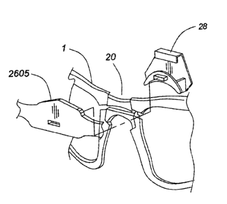
According to the present invention, the there is provided a locking element
such as
lens transfer vise-lock element 28 for clamping the bridge of the eyewear
frame and
preventing the Lens frames from releasing the held lenses. The locking element
has a "C"
shaped cross-section as seen in Figure 25b. The locking element including a
planar main
portion 2505, an upper portion relatively proximate to the nosepiece of the
eyewear and a
lower portion 2525 relatively distant from the nosepiece, a descending upper
flange 2515
attached to the upper portion and a rising lower flange attached to the lower
portion 2525.
A tab 2510 is provided on the rising lower flange. This tab serves three
functions:
providing a grip element for sure grip of the lens transfer visa-lock element
by the user;
serving as a lever to allow greater torque to be applied in removing the lens
transfer vise~lock
element from the bridge of the eyewear; and serving as a protrusion onto which
the optical
adapter can be mounted. The tab protrudes from the plane of the rising lower
flange and
extending away from the main portion. The tab allows the user to apply
leverage by pulling
on the end of the lever member. This causes the lens transfer viso-lock
element to rotate about
the top of the bridge, greatly facilitating the removal of the lens transfer
vise-Iock element
from the frame. In addition, the user's grip is much more secure and the
action of removing
the lens transfer vise-lock element can be performed more surely. The tab is
provided with a
locking tooth 2530.
An optical adapter 2600 is illustrated in Figures 26a, 26b and 26c. The
optical adaptor
allows the user to use corrective lenses when wearing the eyewear of the
present invention.
The optical adaptor is fitted with prescription corrective lenses and mounted
to the eyewear.
The optical adapter includes a central bridge portion 2605 having slot 2610.
The slot
corresponds with the shape of the tab 2510. Referring to Figures 53 to 56, the
oftical adapter
is mounted to the frame of the eyewear by orienting the frame of the optical
adaptor to match
that of the eyewear, placing the optical adapter behind the frame and seating
the slot over the
tab. Pressing on the bridge of the optical adapter while bracing the frarr~e
causes the slot to
slide along the tab until the optical adapter abuts against the back of the
frame. At this point,
the optical adapter is securely mounted onto the frame. Preferably a locking
tooth 2530 is
provided on the tab for mating with the corresponding recess 2615 in the wall
of the slot of
CA 02430360 2003-05-29
17
the optical adaptor to provide a positive engagement. Preferably the locking
tooth has a
ramped portion to facilitate mounting of the optical adaptor.
Figures 51 to 52 illustrate installation of the optical adaptor. Referring to
Figure 51,
the optical adaptor is installed on the inside of the frame as shown in Figure
51. The small
rectangular hole at the center of the adaptor is placed over the corresponding
notch on the
vise-lock above the bridge area of the eyewear frame. The optical adaptor is
then pressed
down firmly using your thumb until the optical adaptor snaps into place.
Referring to Figure 52, the optical adaptor is removed by gripping it with
thumb and
forefinger near the rectangular hole at the center as shown in Figure 52.
Pulling firmly on the
adaptor separates it from the frame. Wiggling the adaptor slightly can
facilitate removal. The
optical adaptor is not fitted with prescription lenses. The optical adaptor
comes with the
blank lenses that must be replaced with lenses fitted to the user's
prescription by a licensed
optician. The optical adaptor can be fitted with prescription lenses for most
people, however,
people wearing bifocals or requiring very strong corrective lenses, will not
be able to use the
optical adaptor.
A typical embodiment of the eyewear system includes: a frame; light
equalization
lenses; limiter lenses; enhancer lenses; microslot adjustable arms; sport
arms; sport visor; one
or more lens transfer vise-lock elements; a headband with side shields; an
adjustable neck and
head strap; an optical adapter; a microfiber cleaning unit; and a storage
case. Preferably the
microfiber cleaning unit is in the form of a storage bag.
The eyewear system of the present invention affords many advantages not
realized by
conventional eyewear. In order to facilitate the easy use, storage and access
to the different
components, the system includes a storage container such as a portable
compartmentalized
carrying case. The case ensures that the components are easily accessible when
desired for use
and protects fragile components such as the different sets of lenses when in
storage. Refernng
to Figures 20 to 23, the carrying case 2000 includes a bottom, a back wall
2020, a wrap
around front wall 2025 and a lid 2010. The lid is hinged to the back wall
along the fold 2040.
A suitable fastener such as a zipper 2005 is provided to allow convenient and
secure closure
of the case. Loops 2055 provided on the outside of the back wall allow the
carrying case to be
belt-mounted. A lanyard clip (not shown) is provided to allow the case to be
fastened to
CA 02430360 2003-05-29
18
clothing. The size of the carrying case allows handy storage, for example, in
a glove
compartment of a car.
The case is dimensioned to fit the folded eyewear into the main compartment.
The lid
is provided with an elongated pouch 2015, which is wide enough to store the
microslot
adjustable arms or the sport arms. It is also suitable for storing smaller
components such as
extra lens transfer vise-lock elements. Mounted to the back wall of the case
is a pair of dual
pouches 2030. Each dual pouch is divided into two pockets. The pockets can be
used to
separate lenses from other components in the case thereby minimizing the
possibility of
breaking or scratching the lenses.
Additional elements such as the headband or the sport visor can be stored in
the main
compartment when not in use. For example, the eyewear configuration
illustrated in Figure 1
includes a frame, light equalization lenses, microslot adjustable arms,
coupling members, and
a lens transfer vise-lock element. The remaining elements which include the
limiter lenses, the
enhancer lenses, the sport arms, the sport visor, any remaining lens transfer
vise~ock
elements, the headband, the adjustable neck and head strap, the optical
adapter and the
microfiber cleaning unit can be stored in the case as follows. The limner
lenses and enhancer
lenses are stored in the pockets of pouches 2030. The sport arms, additional
lens transfer vise
lock elements, the optical adapter and microfiber cleaning unit are stored in
the elongated
pouch. Preferably the optical adapter is stored inside the microfiber storage
bag. The
headband, adaptable strap and sport visor can be stored in the main
compartment, which has
ample room to include the eyewear of Figure 1 when not in use.
It should be understood that the above description is intended to be
illustrative and not
restrictive. A variety of modifications will be apparent to those skilled in
the art within the
sprit and scope of the invention as defined in the appended claims.