Note: Descriptions are shown in the official language in which they were submitted.
CA 02430436 2003-05-29
1
METHOD FOR INTRODUCING A GRANUhAR ORE INTO A ROASTING KIhN
This invention relates to a process of introducing granular
ore into a furnace for calcining the ore at temperatures from
400 to 1050°C, the ore forming a stationary fluidized"bed in
the furnace. When mentioning ore, ore concentrates are also
comprised.
Calcining the ore is an exothermal process. Usually, cooling
bundles are disposed in the stationary fluidized bed, in or-
der to cool the fluidized bed and maintain it at the desired
temperature. The transverse mixing of the solid material is
relatively weakly developed in the stationary fluidized bed;
it is impeded further by the cooling bundles. This leads to
the fluidized bed becoming hotter at the point of introduc-
tion of the ore than at points where no ore is supplied.
Moreover, much sulfur dioxide is obtained at the point of in-
troduction of the ore due to the reaction of the sulfide sul-
fur with the atmospheric oxygen, whereas at paints where lit-
tle or no ore is supplied, little sulfur dioxide can be ob-
tained, so that only little of the atmospheric oxygen offered
is consumed for calcining. In the furnace space above the
CA 02430436 2003-05-29
- 2 -
stationary fluidized bed, there are mostly temperatures above
900°C, and the gas velocities are below,l m/sec.
Because of the high viscosity of the gases, mixing of the gas
streaks rich in sulfur dioxide and of the gas streaks poor in
sulfur dioxide hardly occurs. Therefore, pronounced inhomoge-
neities with respect to temperature, sulfur dioxide concen-
tration and oxygen concentration occur in the furnace space.
In gas streaks which are poor in sulfur dioxide but rich in
oxygen, the undesired sulfatizing of the solid material pref-
erably occurs. This leads to the deterioration of the prod-
_ uct. Furthermore, sulfatized dust tends to form deposits on
the tubes of succeeding waste heat boilers, which deposits
can hardly be removed. The transport of heat from the calcin-
ing gas to the boiler tube is impeded thereby, the costs for
maintaining the boiler are increased, and its availability is
reduced.
It is the object underlying the invention that the ore to be
calcined should approximately uniformly be distributed on the
stationary fluidized bed from the outside. This introduction
should be effected in a rather inexpensive and reliable way.
In accordance with the invention, this is achieved in that
the ore is thrown onto the fluidized bed through an opening
in the furnace housing disposed above the fluidized bed, the
ore being accelerated by blades of a rotating impeller which
is disposed outside the furnace in the vicinity of the open-
ing. The opening in the furnace housing usually is disposed
in a side wall of the housing. In a furnace with large diame-
ter it is possible to provide a plurality of openings in the
furnace housing and to allocate impellers to each of these
openings.
By means of the inventive process, a substantially improved
homogeneity of the temperatures in the fluidized bed and also
in the furnace space above the fluidized bed is achieved. At
CA 02430436 2003-05-29
- 3 -
the same time, there is obtained a more homogeneous distribu-
tion of the sulfur dioxide and oxygen cqncentrations in the
furnace space. The undesired sulfatizing of dust is impeded,
and the product quality and also the operation of the suc-
ceeding waste heat boiler are improved thereby.
Expediently, the rotational speed of the impeller is designed
to be variable, in order to be able to vary the length of
throw upon introduction. It is furthermore expedient to de-
sign the impeller so as to be pivotable or movable with re-
spect to the furnace, whereby the throwing direction for the
ore can be varied. The movability of the impeller can also be
,. advantageous during maintenance work. The pivotability of the
impeller can for instance be produced in that the impeller is
mounted on a vertical, rotatable axle. Instead of the axle
there may also be provided a horizontal rail on which the im-
peller is disposed by means of a movable_supporting device.
For calcining purposes, granular ore is charged into the fur-
nace, e.g. zinc blende, gold ore or pyrite or concentrates of
these ores. The ores may e.g. be granulated prior to calcin-
mg.
Embodiments of the process will be explained with reference
to the drawing, in which:
Fig. 1 shows a vertical section through a calcining furnace
with associated impeller, and
Fig. 2 shows an embodiment of the impeller as seen against
the throwing direction.
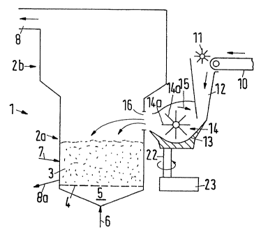
The calcining furnace (1) has a housing with a lower, ap-
proximately cylindrical housing part (2a) and an upper, ex-
panded housing part (2b). The ore to be calcined forms a sta-
tionary fluidized bed (3) on a grid (4) through which passes
CA 02430436 2003-05-29
- 4 -
fluidizing air, which comes from the distribution chamber
(5), in upward direction. The air, which preferably is pre-
heated, is supplied via line (6). If necessary, additional
fuel which may be solid, liquid or gaseous, is introduced
into the fluidized bed (3) through line (7) or also through a
plurality of lines. Exhaust~gas is discharged via the passage
(8) and supplied to a dedusting, cooling and cleaning (not
shown). Part of the calcined product is obtained via the pas-
sage (8), another part is obtained via the discharge'line
(8a).
The ore to be calcined, which may be moist, is supplied via a
conveyor belt (10), and a toothed roll (11) serves to commi-
nute lumps. The ore then drops through a duct (12) into a
trough (13) and is seized by a rotating impeller (14). The
direction of rotation of the impeller (14) is indicated by
the arrow (15). The blades (14a) of the impeller seize the
granular ore and throw it through the opening (16) in .the
lower housing part (2a) onto the fluidized bed (3).
Fig. 2 shows a view of the blades (14a) of the impeller, the.
horizontal shaft (15) belonging to the impeller, on which
shaft the blades are mounted, and of the motor (18) for driv-
ing the shaft (15), with a coupling (19) disposed therebe-
tween. As shown in Fig. 2, the trough (13) constitutes a sup-
porting device also for the motor (18). The impeller is
partly surrounded by a housing (20).
The impeller (14) and the trough (13), the motor (18), the
duct (12), the shaft (15) and the coupling (19) are designed
so as to be movable together, so that the throwing direction
of the impeller (14) is variable. This can be effected by
means of a vertical support (22) for these parts, and from a
stationary drive (23), this support can be swivelled about
its vertical longitudinal axis. Another possibility for
variation consists in that the rotational speed of the impel-
CA 02430436 2003-05-29
- 5 -
ler can be varied, whereby the length of throw of the ore
thrown through the opening (16) onto the fluidized bed (3)
can be varied. In this way, the introduction of the ore onto
the fluidized bed can be effected variably and virtually the
entire surface of the fluidized bed can be covered with ore
to be calcined.
Between the housing opening (16) and the outlet of the impel-
ler (14), which lies between the trough (13) and the upper
housing part (20), e.g. a tubular, flexible bellows may be
arranged, in order to prevent the exit of dust. For a better
clarity, this bellows was omitted in the drawing.
Example:
In a plant corresponding to the drawing, the procedure is as
follows:
A large calcining furnace for zinc blende concentrate (grain
sizes: 98 wt-o smaller than 50 hum) has an inside diameter of
12.5 m. It includes a stationary fluidized bed in which the .
zinc blende concentrate is calcined at about 950°C. Because
of the refractory lining, the furnace wall has a thickness of
450 mm. 40 t/h concentrate with a mean humidity of 8 wt-% are
continuously charged into the calcining furnace.
An impeller (14) with a hub diameter of 400 mm with 6 blades
(14a) having a width of 250 mm and a height of 80 mm delivers
this mass flow into the furnace. The distance of the swivel
axis (22) from the center of the furnace is 7.2 m. The rotat-
ing impeller delivers the ore concentrate into the furnace,
scattering both laterally and in throwing direction. In the
furnace, an ore heap is formed, whose highest point will fur-
thermore be used to describe the throwing behavior and is re-
ferred to as throwing point. The distance of the throwing
point from the swivel axis is referred to as length of throw.
CA 02430436 2003-05-29
- 6 -
The rotational speed of the drive (18) is varied such that
the smallest length of throw is 3.2 m and the largest length
of throw is 11.2 m. The horizontal opening angle of the scat-
ter range is about 25°; with a length of throw of 7.2 m, the
ore heap has a width of about 3.2 m. If the impeller is swiv-
elled from its central position by ~ 28° and the length of
throw is adjusted to be about 8.2 m, the lateral areas of the
furnace will also be reached. Rotational speed and~swivel
movement are now varied at the same time, so that the throw-
ing point in the furnace approximately describes a circular
path around the center of the furnace, the diameter of the
._ circular path being 8.0 m. The time for a revolution on the
circular path is 10 min. Thereby, a rather uniform distribu-
tion of the ore concentrate over the furnace cross-section is
achieved.