Language selection

Search

Patent 2430510 Summary

Third-party information liability

Some of the information on this Web page has been provided by external sources. The Government of Canada is not responsible for the accuracy, reliability or currency of the information supplied by external sources. Users wishing to rely upon this information should consult directly with the source of the information. Content provided by external sources is not subject to official languages, privacy and accessibility requirements.

Claims and Abstract availability

Any discrepancies in the text and image of the Claims and Abstract are due to differing posting times. Text of the Claims and Abstract are posted:

  • At the time the application is open to public inspection;
  • At the time of issue of the patent (grant).
(12) Patent: (11) CA 2430510
(54) English Title: A METHOD OF PREVENTING AIR BYPASS IN A FILTER BANK AND A FILTER ASSEMBLY
(54) French Title: METHODE PERMETTANT D'EMPECHER LA DERIVATION D'AIR DANS UN BANC DE FILTRES, ET FILTRE
Status: Deemed expired
Bibliographic Data
(51) International Patent Classification (IPC):
  • B01D 35/30 (2006.01)
  • B01D 46/10 (2006.01)
  • B01D 46/12 (2006.01)
(72) Inventors :
  • SUTTON, DARREL (Canada)
  • GRANVILLE, ARREN (Canada)
  • BENOIT, MIKE (Canada)
(73) Owners :
  • B.G.E. SERVICE & SUPPLY LTD. (Canada)
(71) Applicants :
  • B.G.E. SERVICE & SUPPLY LTD. (Canada)
(74) Agent: WOODRUFF, NATHAN V.
(74) Associate agent:
(45) Issued: 2008-04-08
(22) Filed Date: 2003-05-30
(41) Open to Public Inspection: 2004-11-30
Examination requested: 2005-03-18
Availability of licence: N/A
(25) Language of filing: English

Patent Cooperation Treaty (PCT): No

(30) Application Priority Data: None

Abstracts

English Abstract

A method of preventing air bypass in a filter bank and a filter assembly in accordance with the teachings of the method. Filter panels are inserted through an access opening of a filter bank. As the filter panels are inserted they are connected in side by side relation with " I" shaped connectors. The sides of adjoining filter panels are inserted into opposed channels of the " I" shaped connectors. The positioning of the " I" shaped connector prevents air bypass between the sides of adjacent filter panels.


French Abstract

Une méthode permettant d'empêcher la dérivation d'air dans un bac de filtres, et un filtre conformément aux instructions de la méthode. Des panneaux filtrants sont insérés par une ouverture d'accès d'un bac de filtres. € mesure que les panneaux filtrants sont insérés, ils sont raccordés côte à côte avec des connecteurs en I. Les côtés des panneaux filtrants contigus sont insérés dans des canaux opposés des connecteurs en I. Le positionnement du connecteur en I empêche la dérivation d'air entre les côtés de panneaux filtrants adjacents.

Claims

Note: Claims are shown in the official language in which they were submitted.


6

THE EMBODIMENTS OF THE INVENTION IN WHICH AN EXCLUSIVE
PROPERTY OR PRIVILEGE IS CLAIMED ARE DEFINED AS FOLLOWS:

1. A method of preventing air bypass in a filter bank, the
method comprising of the steps of:
providing a filter bank having a filter track,
consisting of parallel spaced tracks, which receives filter
in side by side abutting relation inserted through an access
opening;
providing a plurality of rectangular filter panels, each
filter panel having an opposed pair of first sides, an
opposed pair of second sides, two opposed faces, and a width
between the two opposed faces;
providing "I" shaped connectors, that are discrete from
the filter bank, having a length substantially the same as
the length of the opposed pair of second sides of the filter
panels and opposed channels having an inner dimension
substantially equal to the width of the filter panels; and
inserting the filter panels through the access opening
into the filter bank with the first sides of each filter
engaging the filter tracks and sequentially connecting the
filter panels in side by side relation with the "I" shaped
connectors by placing the second sides of abutting filter
panels into the opposed channels of the "I" shaped
connectors, such that the positioning of the "I" shaped
connector prevents air bypass between the second sides of
adjacent filter panels.


2. A filter assembly, comprising:
a filter bank having a filter track, consisting of
parallel spaced tracks, which is adapted to receive more than


7

one filter arranged in side by side abutting relation through
an access opening;
rectangular filter panels, each of the filter panels
having an opposed pair of first sides, an opposed pair of
second sides, two opposed faces, and a width between the
opposed faces;
"I" shaped connectors, discrete from the filter bank,
having a length substantially the same as the length of the
opposed pair of second sides of the filter panels and opposed
channels having an inner dimension substantially equal to the
width of the filter panels; and
the first sides of the filter panels engaging the filter
tracks and the filter panels being connected in side by side
relation with the "I" shaped connectors with the second sides
of abutting filter panels in the opposed channels of the "I"
shaped connectors, such filter the positioning of the "I"
shaped connector prevents air bypass between the sides of
adjacent filter panels.


3. The method as defined in claim 1, further comprising the
step of providing only a single side access opening as the
access opening.


4. The filter assembly as defined in claim 2, wherein the
access opening is a single side access opening.


5. A method of preventing air bypass in a filter bank, the
method comprising of the steps of: providing a filter bank
having a filter track consisting of parallel spaced apart
tracks for receiving at least two sequential arranged and


8

closely adjacent filter panels via an access opening in the
filter bank;
providing two filter panels with each of the two filter
panels having a pair of opposed first sides, a pair of
opposed second sides, a pair of opposed faces, a height
defined by a distance between the pair of opposed first sides
and a width defined a distance between the pair of opposed
faces;
providing at least one "I" shaped connector which is
separated and discrete from the filter bank, the at least one
"I" shaped connector having a length substantially equal to
the height of the two filter panels and having a pair of
opposed channels with suitable for receiving one of the
second sides of the two filter panels and an internal width
dimension substantially equal to the width of each of the two
filter panels: sequentially inserting the two filter panels
through the access opening, one after the other, such that
the first sides of each sequentially inserted filter panel
engages with and are guided along with the filter track; and
inserting the "I" shaped connector between the second
sides of the two sequentially inserted and adjacent filter
panels such that each one of the pair of opposed channels at
the "I" shaped connector receives one of the second sides of
the two filter panels and, during operation of the filter
bank, the "I" shaped connector, restricts air from bypassing
between the second sides of the two adjacent filter panels.


Description

Note: Descriptions are shown in the official language in which they were submitted.


CA 02430510 2003-05-30
1
TITLE OF THE INVENTION:
A method of preventing air bypass in a filter bank and a
Filter Assembly
FIELD OF THE INVENTION
The present invention relates to a method of preventing
air bypass in a filter bank in which fi1_ters are positioned
in side by side relation along a filter track, and a filter
assembly constructed in accordance with the teachings of the
method.
BACKGROUND OF THE INVENTION
In filter banks, filter panels are inserted through an
access opening into a filter track. The filter panels are
arranged along the filter track in side by side relation.
Air will always follow the path of least resistance. A
problem presently being encountered with filter banks is that
of air passing between the filter panels and bypassing the
filters altogether.
SU1~1ARY OF THE INVENTION
What is required is a method of preventing air bypass in
filter banks, and a filter assembly constructed in accordance
<?5 with the teachings of the method.
According to a first aspect of the present invention
there is provided a method of preventing air bypass in a
filter bank. A first step involves providing a filter bank
having a filter track with an access opening. A second step
involves providing rectangular filter panels. Each filter
panel has an opposed pair of first sides, an opposed pair of
second sides, two opposed faces, and a width between the two


CA 02430510 2003-05-30
2
opposed faces. A third step involves providing " I" shaped
connectors having a length substantially the same as the
length of the opposed pair of second sides of the filter
panels. The " I" shaped connectors have opposed channels
with an inner dimension substantially equal to the width of
the filter panels. A fourth step involves inserting the
filter panels through the access opening into the filter bank
and sequentially connecting the filter panels in side by side
relation with the " I" shaped connectors by placing the
second sides of adjoining filter panels into the opposed
channels of the " I" shaped connectors. The positioning of
the " I" shaped connector prevents air bypass between the
sides of adjacent filter panels.
According to a second aspect of the present invention
there is provided a filter assembly which includes a filter
bank having a filter track adapted to receive filter panels
in side by side relation through an access opening.
Rectangular filter panels are provided. Each of the filter
panels has an opposed pair of first sides, an opposed pair of
second sides, two opposed faces, and a width between the two
opposed faces. " I" shaped connectors are provided having a
length substantially the same as the length of the opposed
pair of second sides of the filter panels and opposed
'?5 channels having an .inner dimension substantially equal to the
width of the filter panels. The filter panels are connected
in side by side relation by the " I" shaped connectors with
the second sides of adjoining filter panels in the opposed
channels of the " I" shaped connectors. The positioning of
the " I" shaped connector prevents air bypass between the
sides of adjacent filter panels.
RDTTi!Ti~ TITi!Cf'DTDTTC1N ffTi' TT1F TIRnWTNCS


CA 02430510 2003-05-30
3
These and other features of the invention will become
more apparent from the following description in which
reference is made to the appended drawings, the drawings are
for the purpose of illustration only and are not intended to
in any way limit the scope of the invention to the particular
embodiment or embodiments shown, wherein:
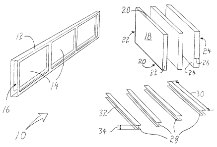
FIGURE 1 is a perspective view of the components
necessary to assemble the filter assembly in accordance with
the teachings of the present invention.
FIGURE 2 is a top plan view of the filter panels being
connected by " I" shaped connectors as they are inserted into
the filter track of the side access filter bank.
FIGURE 3 is a top plan view, in section, of a filter
assembly in a side access filter bank in accordance with the
1.5 teachings of the present invention.
FIGURE 4 is a side elevation detail view of an " I"
shaped connector.
FIGURE 5 is a perspective view of a front loading filter
bank.
FIGURE 6 is an end view in sequence illustrating a
filter being loaded in a back loading filter bank.
FIGURE 7 labelled as pRIOR ARTS is a perspective cut
away view of a filter assembly in a side access filter bank.
DETAILED DESCRIPTION OF THE PREFERRED E1~ODIMENT
The preferred embodiment, a filter assembly generally
identified by reference numeral 10, will now be described
with reference to FIGURES 1 through 5.
30 Referring to FIB ~, there is illustrated a PRIOR ART
filter assembly in a side access filter bank. The side
access filter bank is generally indicated by reference
numeral 200. Filter bank 200 has a filter track 202 (one
with capacity for three filters has been selected for


CA 02430510 2003-05-30
4
illustration). Air flow is indicated by arrows 206. It is to
be noted the air bypass which occurs between adjacent filter
panels 204.
Structure and Relationship of Parts:
Referring to gIG~ 1. the components which make up
filter assembly 10 are illustrated: a side access filter bank
12 having a filter track 14 with a single side access opening
16. Positioned in side by side relation along the filter
track are filter panels 18. Each filter panels 18 has an
opposed pair of first sides 20, an opposed pair of second
sides 22, two opposed faces 24, and a width 26 between the
two opposed faces. In the illustrated embodiment, filter
panels 18 are rectangular. " I" shaped connectors 28 having
a length 30 substantially the same as the length of the
opposed pair of second sides 22 of filter panels 18 and
having opposed channels 32 having an inner dimension 34
substantially equal to width 26 of filter panels 18.
?0
Operation:
The manner of assembly of filter assembly 10 in
accordance with the teachings of the preferred method will
now be described with reference to FIGURES 1 through 4.
?5 Referring to FIGURE 2, each filter panel 18 is sequentially
inserted into filter bank 12 through access opening 16. As
each filter panel 18 is inserted, each second side 22 is
fitted with an " I" shaped connector 28. Referring to FIGURE
4, " I" shaped connector 28 i.s adapted for a close tolerance
30 fit with each second side 22 of each filter panel 18 such
that inner dimension 34 and width 26 are substantially equal
resulting in a complete seal. Referring to FIGS 3~
completed filter assembly 10 is shown. In the illustrated
embodiment, " I" shaped connectors 28 are also used to seal


CA 02430510 2003-05-30
the ends of the chosen filter configuration. The overall
result is that air flow, following the path of least
resistance as indicated by arrows 36, is directed through
filter panels 18.
5
Variation:
The above described innovation is not limited in its
application to side loading filter assemblies, it is equally
applicable to front or rear loading filter assemblies.
Referring to FIGURES 5 and 6, in the illustrated embodiment,
filter tracks 38 are oriented so as to allow for front or
rear loading. " I" shaped connectors 28 remain in close
tolerance fit with filter panels 18. Referring to FIGURE 6~
filter panel 18 is loaded (from left to right) by tilting and
installing upwards and then resting in place.
In this patent document, the word "comprising" is used
in its non-limiting sense to mean that items following the
word are included, but items not specifically mentioned are
not excluded. A reference to an element by the indefinite
article "a" does not exclude the possibility that more than
one of the element is present, unless the context clearly
requires that there be one and only one of the elements.
It will be apparent to one skilled in the art that
modifications may be made to the illustrated embodiment
without departing from the spirit and scope of the invention
as hereinafter defined _in the Claims.

Representative Drawing
A single figure which represents the drawing illustrating the invention.
Administrative Status

For a clearer understanding of the status of the application/patent presented on this page, the site Disclaimer , as well as the definitions for Patent , Administrative Status , Maintenance Fee  and Payment History  should be consulted.

Administrative Status

Title Date
Forecasted Issue Date 2008-04-08
(22) Filed 2003-05-30
(41) Open to Public Inspection 2004-11-30
Examination Requested 2005-03-18
(45) Issued 2008-04-08
Deemed Expired 2020-08-31

Abandonment History

There is no abandonment history.

Payment History

Fee Type Anniversary Year Due Date Amount Paid Paid Date
Application Fee $300.00 2003-05-30
Registration of a document - section 124 $100.00 2003-07-16
Request for Examination $800.00 2005-03-18
Maintenance Fee - Application - New Act 2 2005-05-30 $100.00 2005-03-18
Maintenance Fee - Application - New Act 3 2006-05-30 $100.00 2006-03-16
Maintenance Fee - Application - New Act 4 2007-05-30 $100.00 2007-03-06
Final Fee $300.00 2008-01-17
Maintenance Fee - Patent - New Act 5 2008-05-30 $200.00 2008-04-01
Maintenance Fee - Patent - New Act 6 2009-06-01 $200.00 2009-05-29
Maintenance Fee - Patent - New Act 7 2010-05-31 $200.00 2010-05-10
Maintenance Fee - Patent - New Act 8 2011-05-30 $200.00 2011-05-30
Maintenance Fee - Patent - New Act 9 2012-05-30 $200.00 2012-05-08
Maintenance Fee - Patent - New Act 10 2013-05-30 $250.00 2013-05-07
Maintenance Fee - Patent - New Act 11 2014-05-30 $250.00 2014-05-21
Maintenance Fee - Patent - New Act 12 2015-06-01 $250.00 2015-04-09
Maintenance Fee - Patent - New Act 13 2016-05-30 $250.00 2016-05-30
Maintenance Fee - Patent - New Act 14 2017-05-30 $250.00 2017-03-16
Maintenance Fee - Patent - New Act 15 2018-05-30 $450.00 2018-04-13
Owners on Record

Note: Records showing the ownership history in alphabetical order.

Current Owners on Record
B.G.E. SERVICE & SUPPLY LTD.
Past Owners on Record
BENOIT, MIKE
GRANVILLE, ARREN
SUTTON, DARREL
Past Owners that do not appear in the "Owners on Record" listing will appear in other documentation within the application.
Documents

To view selected files, please enter reCAPTCHA code :


To view images, click a link in the Document Description column. To download the documents, select one or more checkboxes in the first column and then click the "Download Selected in PDF format (Zip Archive)" or the "Download Selected as Single PDF" button.

List of published and non-published patent-specific documents on the CPD .

If you have any difficulty accessing content, you can call the Client Service Centre at 1-866-997-1936 or send them an e-mail at CIPO Client Service Centre.


Document
Description 
Date
(yyyy-mm-dd) 
Number of pages   Size of Image (KB) 
Abstract 2003-05-30 1 16
Description 2003-05-30 5 211
Claims 2003-05-30 2 59
Drawings 2003-05-30 5 78
Representative Drawing 2003-10-02 1 14
Cover Page 2008-03-11 1 42
Cover Page 2004-11-05 1 40
Claims 2006-08-28 3 109
Correspondence 2003-07-04 1 25
Assignment 2003-05-30 2 69
Assignment 2003-07-16 3 204
Fees 2007-03-06 1 27
Correspondence 2011-04-26 1 17
Correspondence 2011-04-26 1 22
Prosecution-Amendment 2005-03-18 1 30
Fees 2005-03-18 1 30
Fees 2006-03-16 1 28
Prosecution-Amendment 2006-08-28 6 181
Correspondence 2008-01-17 1 26
Fees 2008-04-01 1 28
Fees 2009-05-29 1 201
Correspondence 2011-03-31 3 158
Fees 2015-04-09 1 33
Fees 2016-05-30 1 33