Note: Descriptions are shown in the official language in which they were submitted.
CA 02431050 2003-06-06
WO 02/47288 PCT/USO1/47152
SYSTEM AND METHOD FOR INBAND SIGNALING FOR SECTOR
SYNCHRONIZATION IN A WIRELESS COMMUNICATION SYSTEM
RELATED APPLICATIONS
The present application is related to co-pending, commonly assigned U.S.
patent application serial number 09/434,707, entitled "SYSTEM AND METHOD
FOR BROADBAND MILLIMETER WAVE DATA LOCATION," co-
pending, commonly assigned U.S. patent application serial number 09/604,437,
entitled "MAXIn~IIZING EFFICIENCY IN A MULTI-CARRIER TIME DIVISION
DUPLEX SYSTEM EMPLOYING DYNAMIC ASYMMETRY," and co-pending,
commonly assigned U.S. patent application serial number 09/607,456, entitled
"FREQUENCY REUSE FOR TDD," which are incorporated herein by reference.
The present application is also being filed simultaneously with a commonly
assigned
U.S. patent application entitled "SYSTEM AND METHOD FOR FREQUENCY RE-
USE IN A SECTORIZED CELL PATTERN IN A WIRELESS COMMUNICATION
SYSTEM".
CA 02431050 2003-06-06
WO 02/47288 PCT/USO1/47152
BACKGROUND OF THE INVENTION
The present invention relates to communication systems and methods
and more particularly to a system and method for optimizing the bandwidth of
a point to multipoint wireless system by synchronizing transmit and receive
modes.
Wireless radio links have increasingly become important to provide data
communication links for a variety of applications. For example, Internet
Service Providers have begun to utilize wireless radio links within urban
settings to avoid the installation expense of traditional wired connections or
optical fiber. It may be advantageous to utilize wireless radio link systems
to
provide service to a plurality of users in a point to multipoint architecture.
Point to multipoint systems typically consist of a plurality of hub units
servicing a plurality of sub units (sometimes referred to as remote units,
nodes,
or subscriber units). The subs are typically associated with individual nodes
on
the system. For example, an individual sub unit may be connected to LAN to
allow PC's on the LAN to bridge to other networks via the point to multipoint
system. Each sub unit communicates via a wireless channel with a particular
hub unit. In a point to multipoint system, the hub unit may control
communication between a portion of the plurality of sub units associated with
a
particular coverage area. The hub units schedule transmit and receive bursts
to
and from sub units. The hub units may distribute data packets received from a
particular sub unit to another sub unit within the same coverage area via such
frames, to a traditional wired network backbone, or to another hub unit.
A point to multipoint system, such as disclosed in the above referenced
and commonly assigned patent application entitled "FREQUENCY REUSE
FOR TDD," contains a plurality of adjacently located hub units providing an
aggregate coverage area. Additionally, these hubs may have their individual
coverage areas divided into particular sectors - such as 30 or 90 degree
sectors.
Additionally, the hubs may utilize frequency division or other techniques to
provide a plurality of communication channels.
2
CA 02431050 2003-06-06
WO 02/47288 PCT/USO1/47152
Channel reuse techniques have developed to allow reuse of channels
within a network without introducing unacceptable levels of interference. The
purpose of these channel reuse techniques is maximize channel availability
while avoiding co-channel interference between neighboring hubs. Clearly,
these channel reuse techniques are valuable tools to increasing the bandwidth
of point to multipoint systems. However, according to the present invention it
has been realized that point to multipoint systems contain architectural
characteristics that may be exploited to allow optimization of channel
availability greater than that available with traditional channel reuse
techniques
while avoiding co-channel interference.
For example, data traffic over a point to multipoint system may be
bursty, rather than at a fixed or continuous data rate. Specifically, an
Internet
browser application executed on a sub unit would typically require significant
down link bandwidth while downloading HTML code from a website, but
would require little or no bandwidth while a user reads the display associated
with the HTML code. Additionally, the bandwidth requirements of many
applications such as browsers may be asymmetric. Specifically, Internet
browsers often download a large amount of data, but upload proportionally
very little. Accordingly, point to multipoint systems may implement dynamic
bandwidth allocation (DBA) techniques to maximize the data throughput
associated with asymmetric, bursty traffic.
Accordingly, it is an object of the present invention to provide a system
and method to maximize the bandwidth of point to multipoint systems in
accordance with the unique characteristics of point to multipoint systems as
between particular portions of the network.
It is an additional object of the present invention to provide a system and
method for synchronized dynamic allocation of bandwidth.
It is an additional object of the present invention to provide a system and
method for synchronization of receive and transmit modes of sectors or other
3
CA 02431050 2003-06-06
WO 02/47288 PCT/USO1/47152
portions of an associated group of hub units to maximize the bandwidth of
point to multipoint systems.
It is an additional object of the present invention to provide a system and
method for sector to sector telemetry in point to multipoint systems.
It is an additional object of the present invention to provide an efficient
communication channel for use with the invention systems and methods that
allows synchronization of neighboring hubs while permitting rapid dynamic
allocation of bandwidth in individual hubs.
It is still an additional object of the present invention to provide a pattern
of frequency re-use in a wireless communication system.
It is another object of the present invention to provide a repeatable
pattern of frequency re-use in a wireless communication system comprised of
sixteen cells in a four-by-four grid using two polarizations per communication
frequency.
It is yet another object of the present invention to provide a repeatable
pattern of frequency re-use in a wireless communication system comprised of
sixteen cells grouped in four sub-clusters of four cells in which facing
sectors
in the pattern are synchronized.
It is a further object of the present invention to provide a method of
reducing co-channel and/or adj acent channel interference by a pattern of
frequency re-use.
These and other objects, features and technical advantages are achieved
by a system and method which operate in a point to multipoint system
comprising a plurality of hubs and a plurality of subs distributed within
coverage areas associated with the hubs. The point to multipoint system
preferably divides its communication bandwidth into channels utilizing
spectrum division techniques, such as frequency division, time division, or
orthogonal code division. Also, the hubs communicate to the subs within their
coverage areas via sector antennae. By utilizing spectrum division and sector
antennas, preferred embodiments of the point to multipoint system coordinate
4
CA 02431050 2003-06-06
WO 02/47288 PCT/USO1/47152
channel allocation via a channel reuse plan. Additionally, preferred
embodiments divide individual channels into transmit and receive modes via a
Time Duplex Division (TDD) scheme via the same channel. In this TDD
scheme, a hub transmits information to subs in the transmit mode and receives
information from subs in the receive mode. Moreover, the hubs of the point to
multipoint system preferably may dynamically allocate bandwidth between the
transmit and receive modes to achieve asymmetric communication modes.
Also, the preferred embodiment subs utilizing the present invention comprise
directional antenna.
Co-channel interference such as in adjacent sectors of neighboring hubs
is a significant concern. Specifically, hub to hub exposure is problematic,
since
hub antennas are typically directed toward other hubs of the network in order
to
provide composite coverage of a service area. For example, preferred
embodiment hubs may utilize sector antennas covering between 30 to 90
degrees in azimuth, which are oriented to face similar sector antennas at
neighboring hubs. Sub unit exposure is not as a significant issue for the
preferred embodiments point to multipoint systems, because sub units of these
point to multipoint systems utilize highly directional antenna. Accordingly,
the
subs units may not be exposed to significant co-channel interference from
other
sub units or other hub units.
Channel reuse plans may be utilized to mitigate hub t~ hub co-channel
interference. For example, by carefully assigning channels for use by the hubs
of a network, reuse performance of approximately 1 may be achieved.
Moreover, through advanced channel planning techniques, such as shown and
described in the above referenced patent application, entitled "FREQUENCY
REUSE FOR TDD", and as described below, higher channel reuse
performance may be achieved.
Nonetheless, a method or system optimization that would permit greater
channel reuse would allow greater bandwidth for the system as a whole. The
present invention achieves this goal in one embodiment by synchronizing
CA 02431050 2003-06-06
WO 02/47288 PCT/USO1/47152
transmit and receive modes of hubs. One embodiment of the present invention
synchronizes dynamic bandwidth allocation of facing sectors of a cluster of
geographically adjacent hubs, while allowing other sectors of these hubs to
independently allocate bandwidth through frequency reuse and facing sector
synchronization. The hubs are adjacent in the sense that the hubs are the
nearest neighbor hubs in a particular direction. In this embodiment, guard
time
between transmit and receive modes is minimized by preferably selecting a
guard time to accommodate the synchronization distance of just over two hub
coverage radii. For example, where a maximum reuse is 6R, a reuse schedule
of 9, with 30 degree sectors, 4.5 km cells, the guard time is approximately
a 100~s or approximately 5 % of the embodiment's channel capacity to
accommodate propagation from a maximum distance in the reuse cluster.
However, as the present invention synchronizes facing sectors of adjacent
hubs,
the synchronization distance is greatly reduced. Accordingly, in this
embodiment, the guard time only occupies .5 % of the channel capacity.
Moreover, the computation requirements of the system are significantly
reduced in this preferred embodiment, as a much smaller portion of the
network is synchronized with respect to any particular synchronization
determination. Also, the facing sector synchronization simplifies the
implementation of synchronization telemetry.
In another embodiment of the present invention, a pattern of frequency
re-use is described where a repeatable pattern of cells is employed to allow
for
re-use of a number of frequency assignments where there are two polarization
modes available per frequency. Such a pattern of frequency re-use is
especially
useful when the number of frequency assignments, or communication channels,
available for operation of a communication system is limited. In order to
provide sufficient coverage for a particular operating area, a pattern of
cells that
re-use the available frequencies must be provided in order to avoid dead spots
or to avoid interference between adjacent channels on the frequency spectrum
used in the same area, known in the art as "adjacent channel interference" or
6
CA 02431050 2003-06-06
WO 02/47288 PCT/USO1/47152
interference between two cells using the same frequency with the same
polarization in adjacent areas, known in the art as "co-channel interference".
Idealizing the shape of the cells in the pattern as circular and further
idealizing each cell as having a similar radius, the shape of a repeatable
pattern
of such cells can be viewed as an overlay on a flat surface. Obviously, such
idealizations such as a flat surface and substantially identical cells spaced
at
uniform distances rarely occur in the real world. 'However, it is to be
understood that the present inventive system and method is not limited to such
idealizations but rather is applicable to real world situations where the
overall
frequency re-use pattern can be used while taking into account minor
variations
to allow for obstructions, terrain features, dissimilar cell sizes, irregular
spacing
of cells, etc. While the disclosure of the invention below will discuss an
idealized repeatable pattern composed of idealized cells, etc., such
idealizations
should not be construed as limitations of the invention.
For cells of substantially the same size and circular in shape, one
arrangement of those cells in a mufti-cell pattern may be seen as a square
grid
where the edge of two cells that are adjacent in the same rank or the same
file
are tangent at one point. In such an arrangement, cells that are diagonally
adjacent are not tangent. In another mufti-cell arrangement, a cell in the
pattern
is tangent to each of six adjacent cells. Such a pattern would appear as a
honeycomb shape if the cells are idealized to be hexagonal in shape.
The inventors have determined empirically that for cells with 90°
sectors, a minimum of eight frequency assignments and two polarizations are
required for efficient frequency re-use for broadband wireless access systems.
This is a reasonable requirement of frequency/polarization assignments for
90°
sectorized cells in a time division duplex ("TDD") system considering the size
of a typical license allocation of frequencies on a worldwide basis. For
example, in Europe, the anticipated license allocation is 2 x 112 MHz or 224
MHz for the 28 GHz band and approximately 500 MHz for the 42 GHz band.
Most of the North American broadband wireless access operators have
7
CA 02431050 2003-06-06
WO 02/47288 PCT/USO1/47152
allocations in excess of 200 MHz. An emerging popular channel size is 2g
MHz in Europe and 25 MHz in North America. These channel sizes coupled
with the anticipated license allocation of frequencies allows for eight or
more
available frequency channels.
While 90° sectors have some disadvantages over smaller sector
sizes,
such as 60°, 45°, and 30° sectors, 90° sector size
is the baseline for planning for
almost all broadband wireless access operators and standards groups. For
example, RF performance is somewhat compromised for wide sectors relative
to narrow sectors. Cell diameter is reduced thereby requiring a greater number
of hubs/cells to cover a given area. Wider sectors also give rise to a greater
possibility of co-channel and adjacent channel interference.
Despite the operational drawbacks of 90° sectors, there are
significant
economical advantages to 90° sector plans. One advantage is the lower
cost of
outdoor gear. With 90° sectors, fewer sectors and hence fewer radios,
antennas, and associated equipment, both primary and redundant, are required
when compared with smaller-sized sectors. Additionally, a significant cost to
operators are roof rights. Landlords tend to charge for the right to place
equipment of the roof of their building based on the number of antennas so
90°
sectors translates into lower cost for roof rights. Also, wider sectors
provide
greater RF coverage which is an important benefit in the early deployment of a
system.
The foregoing has outlined rather broadly the features and technical
advantages of the present invention in order that the detailed description of
the
invention that follows may be better understood. Additional features and
advantages of the invention will be described hereinafter which form the
subject of the claims of the invention. It should be appreciated by those
skilled
in the art that the conception and specific embodiment disclosed may be
readily
utilized as a basis for modifying or designing other structures for carrying
out
the same purposes of the present invention. It should also be realized by
those
skilled in the art that such equivalent constructions do not depart from the
spirit
8
CA 02431050 2003-06-06
WO 02/47288 PCT/USO1/47152
and scope of the invention as set forth in the appended claims. The novel
features which are believed to be characteristic of the invention, both as to
its
organization and method of operation, together with further objects and
advantages will be better understood from the following description when
considered in connection with the accompanying figures. It is to be expressly
understood, however, that each of the figures is provided for the purpose of
illustration and description only and is not intended as a definition of the
limits
of the present invention.
BRIEF DESCRIPTION OF THE DRAWINGS
For a more complete understanding of the present invention, and the
advantages thereof, reference is now made to the following descriptions taken
in conjunction with the accompanying drawing, in which:
FIGURE 1 depicts an illustrative example of a point to multipoint
system arranged in a cluster architecture.
FIGURE 2A depicts an illustrative sector configuration for the point to
multipoint system set forth in FIGURE 1.
FIGURE 2B illustrates a sectorized antenna arrangement for a hub for
one of the cells in FIGURE 2A.
FIGURE 3 illustrates particular sectors and the propagation of
transmissions from hubs to a plurality of subs within the particular sectors.
FIGURES 4A to 4D each illustrate a timing diagram for a series of RX
and TX frames associated with opposing sectors of adjacent hubs.
FIGURE 5 illustrates an exemplary power density spectrum for a QAM
carrier signal and an associated Adaptation carrier.
FIGURE 6A illustrates a set of eight frequency channels with two
polarizations per frequency channel for use in a frequency re-use pattern.
9
CA 02431050 2003-06-06
WO 02/47288 PCT/USO1/47152
FIGURE 6B illustrates eight unique cell types using the set of eight
frequency channels with two polarizations per frequency channel illustrated in
FIGURE 6A.
FIGURE 7 illustrates a repeatable pattern of sixteen cells in a four-by-
four rectilinear grid where each cell is divided into four 90° sectors
where
opposing sectors operate on the same frequency channel with the same
polarization.
FIGURE 8 illustrates one group of four cells from the repeatable pattern
of sixteen cells in FIGURE 7.
FIGURE 9 illustrates a repeatable pattern of sixteen cells in a four-by-
four grid forming a parallelogram where each cell is divided into four
90°
sectors where opposing sectors operate on the same frequency channel with the
same polarization.
FIGURE 10 illustrates a repeatable pattern of FIGURE 7 where facing
sectors operate on the same frequency channel and polarization to allow for
transmit and receive synchronization between hub antennas of facing sectors.
CA 02431050 2003-06-06
WO 02/47288 PCT/USO1/47152
FIGURE 11A illustrates the set of eight frequency channels with two
polarizations per frequency channel shown in FIGURE 6A indicating those
frequency channels and polarizations used in the pattern in FIGURE 10 and
those frequency channels and polarizations not used in the pattern of FIGURE
that are held in reserve.
FIGURE 11B illustrates eight unique cell types using the set of four
frequency channels with two polarizations per frequency channel illustrated in
FIGURE 1 1A as being used in the frequency re-use pattern of FIGURE 10.
FIGURE 12 illustrates one group of four cells from the repeatable
pattern of sixteen cells in FIGURE 10.
FIGURE 13 illustrates the repeatable pattern FIGURE 10 with an
overlay of additional frequency channel sectors to accommodate an increase in
the capacity demands of the users of the system.
DETAILED DESCRIPTION
FIGURE 1 illustrates an exemplary point to multipoint system utilizing
the present invention. The system is preferably deployed in a cluster
configuration. The illustrative cluster consists of a plurality of hubs ( 105,
106,
107, 108), although clusters in numbers different than the illustrated
configuration may be employed according to the present invention. It shall be
appreciated that communication networks utilizing the present invention may
include additional clusters, either remotely located or adj acently located,
with
the clusters utilizing the present invention.
Hubs 105, 106, 107, and 108 provide coverage to cells 101, 102, 103,
and 104. A plurality of subs (109 - 119) are deployed in cells 101, 102, 103,
and 104, respectively. In addition, processor systems (120 - 131) are
respectively associated with individual sub units. It shall be appreciated
that
sub units of a point to multipoint system may be alternatively associated with
a
LAN network of processors system. Alternatively, the sub units of point to
multipoint system may be connected to an intermediate network. For example,
11
CA 02431050 2003-06-06
WO 02/47288 PCT/USO1/47152
a sub unit may be connected to an intermediate ATM switch. It shall further be
appreciated that a system employing the present invention may contain an
arbitrarily large number of hubs, cells, and sub units. For simplicity of
describing the present invention, the exemplary embodiment has been
described in terms of four cells.
FIGURE 2A illustrates an exemplary sector configuration of the point to
multipoint system set forth in FIGURE 1. As previously noted, the system is
divided into coverage areas associated with cells 101, 102, 103, and 104.
Moreover, cells 101, 102, 103, 104, of the illustrated embodiment are
sectorized into 90 degree sectors (lOlA-lOlD, 102A-102D, 103A-103D, and
104A-104D), although other sector sizes may be synchronized according to the
present invention. Hubs 105, 106, 107, and 108 transmit and receive signals
to/from the sectors via sector antennas, such as illustrated in FIGURE 2B for
the hub 105. The sector antennas 202A through 202D may utilize a discrete
antenna element for each sector. Alternatively, the sector antennas may
utilize
a plurality of narrow beam antenna elements to synthesize sector coverage. In
this configuration, energy from RF signals transmitted from a sector antenna
associated with any of sectors lOlD, 102C, 103B, and 104A may be detected in
the other sector antennas of this group.
The spectrum allocated to the point to multipoint system as a whole is
preferably subdivided into channels. Numerous methods of channel division
may be utilized with the present invention, such as time division, frequency
division channels, frequency hopping channels, and orthogonal code channels.
The channels are divided into discrete sets. Additionally, the sets of
channels
are allocated among the sectors of the point to multipoint system in
accordance
with a reuse schedule. In this exemplary system, RF signals 302-307 are being
transmitted upon the same channel for the purpose of illustrating the present
invention. It shall be appreciated that other signaling may occur on other
channels concurrently with the exemplary transmit and receive signals.
12
CA 02431050 2003-06-06
WO 02/47288 PCT/USO1/47152
According to a preferred embodiment, at least adjacent sectors of a
particular cell are provided different channel sets according to the channel
reuse plan. For example, the channels assigned for use by sectors 104B and
104C are different from the channels assigned for use by sector 104A.
However, depending upon the front and back isolation of the sector antenna,
side lobe characteristics, and the like, channel sets may be reused in a cell,
such
as within sector 104B and 104C andlor 104A and 104D.
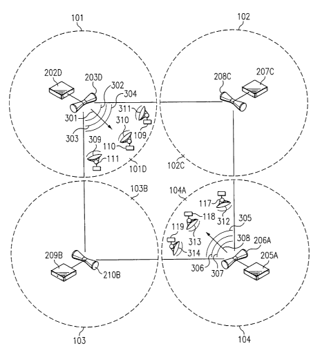
FIGURE 3 illustrates a series of RF transmit signals (301-306) broadcast
from hubs 105 and 106, respectively. Hub 105 transmits a series of RF time
burst or time slot signals (302, 303, and 304) with the signals propagating in
direction 301 within sector lOlD. Since hub 105 utilizes a sector antenna, the
energy associated with RF signals 302, 303, and 304 propagates throughout
sector 101D. RF signal 302 comprises information for sub 109. RF signal 303
comprises information for sub 110. RF signal 304 comprises information for
sub 111. Similarly, hub 108 transmits a series of RF time burst or time slot
signals (305, 306, and 307) with the signals propagating in direction 308
within
sector 104A. Since hub 104 utilizes a sector antenna, the energy associated
with RF signals 305, 306, and 307 propagates through out sector 104A. RF
signal 305 may comprise information for sub 117. RF signal 306 may
comprise information for sub 118. RF signal 307 may comprise information
for sub 119.
Eventually, RF signals 302, 303, and 304 will propagate beyond the
confines of cell 104 into cells 101, 102, and 103. Accordingly, RF signals
302,
303, and 304 could cause co-channel interference in cells 101, 102, and 103.
In
the preferred embodiment point to multipoint system, the sub units utilize
highly directional antennas directed toward an associated hub and therefore
generally away from the remaining hubs of a cluster. Accordingly, the subs
generally will not experience co-channel interference from RF signals 302,
303, and 304.
13
CA 02431050 2003-06-06
WO 02/47288 PCT/USO1/47152
However, hubs 105, 106, and 107 will experience co-channel
interference if the hubs are in receive mode with respect to the particular
channels associated with RF signals 302, 303, and 304 when the RF signals
arrive at the particular hub. According to a preferred embodiment, hub 108
utilizes the same set of channels for sector 104A as hub 105 utilizes for
sector
101D, hub 106 uses for sector 102c, and as hub 107 uses for sector 103b.
Accordingly, RF signals 302, 303, and 304 could cause co-channel interference
depending upon their arnval time at hubs 106, 107, and 108. It shall be
appreciated that RF signals 302, 303, and 304 will have negligible effect if
RF
signals 302, 303, 304 arnve when hubs 106, 107, and 108 are in transmit mode.
Similarly, RF signals 305, 306, and 307 may cause co-channel interference in
hubs 105, 106, and 107, if the hubs are in receive mode with respect to the
channels associated with the signals upon their arnval.
Additionally, the subs in sectors lOlD and 104A broadcast RF signals
309-314. As previously noted, the sub units of the preferred embodiment of
this system utilize highly directional antennas. The architecture of the
system
is such that the highly directional antennas focus the radiated RF energy
within
a very narrow beam centered upon the respective hubs. Accordingly, it is
unlikely that the subs could couple with another antenna in the system to
cause
co-channel interference. It shall be appreciated that this exemplary system
contemplates that RF signals 302-307 and RF signals 309-314 are being
transmitted via the same frequency channel. Accordingly, the exemplary
system illustrating the present invention controls the timing of RF signal
transmissions in TDMA burst periods.
The preferred embodiment of the present invention and method
synchronizes particular transmissions within a point to multipoint system to
prevent hub transmission from causing co-channel interference. Of course,
reception windows may also be synchronized in addition to or in the
alternative
to transmission window synchronization in accordance with the present
invention. Depending upon the amount of isolation between channels, it may
be possible to independently synchronize individual channels in adjacent
14
CA 02431050 2003-06-06
WO 02/47288 PCT/USO1/47152
sectors. By synchronizing individual channels, an adaptive time division
duplex scheme may maximize throughput on a per channel basis. However,
this approach requires greater processing capacity, and hence greater
equipment costs and complexity, to calculate optimal receive and transmit
asymmetries. Accordingly, the preferred embodiment synchronizes
transmission and reception for all channels utilized within adjacent sectors.
In
this manner, the present system and method allows greater performance of the
asymmetric time division duplex algorithms while maintaining costs and
complexity at preferred levels.
FIGURES 4A through 4D set forth exemplary timing diagrams for
transmit and receive frames for sectors lOlD, 102C, 103B, and 104A of hubs
105, 106, 107, and 108. Each hub is preferably synchronized to begin its
transmit mode at time to. Hub 105 transmits TX bursts 401-403, comprising'
information for subs 109-111, respectively. Hub 106 transmits TX burst 404
comprising information for sub 114. Hub 107 transmits bursts 405 and 406,
comprising information for subs 115 and 116, respectively. Hub 108 transmits
bursts 407-409, comprising information for subs 117-119, respectively. Also,
each hub is preferably synchronized to end its transmit mode at time t6.
Additionally, hubs 105-108 are further synchronized such that hubs 105-
108 do not transmit from time t6 to time t~. Also, hubs 105-108 do not receive
bursts from subs from time t6 to time t7. During this period, the delay in
transmission and reception creates guard 316. The duration of guard 316 is
preferably selected so that the RF signals associated with the respective
bursts
will propagate beyond any hub that may experience co-channel interference
before the hub will enter receive mode. Adjacent sector synchronization causes
the synchronization distance for this embodiment to be slightly more than two
hub radii (the distance between hubs 105 and 108). Adjacent sector
synchronization with proper reuse planning is sufficient, because non-
synchronized sectors utilizing the channels will be sufficiently separately
spatially or facing different directions to avoid co-channel interference.
CA 02431050 2003-06-06
WO 02/47288 PCT/USO1/47152
An exemplary discussion of such frequency reuse planning is contained
in the above reference patent application, entitled "FREQUENCY REUSE
FOR TDD." In an environment utilizing frequency use, channels may be
assigned to hubs and their respective sectors by storing assigned channels in
non-volatile memory at a hub which is utilized to physically configure the hub
during a configuration start-up operation. Alternatively, channels may be
assigned upon a dynamic basis in accordance with dynamic channel assignment
algorithms. In this case, a channel controller may implement a particular
dynamic assignment algorithm and periodically communicate assigned
channels to the hubs for use in the respective sectors.
After time t7, hubs 105-108 are synchronized to enter the receive mode.
At this point, hubs 105-108 may receive transmissions from their respective
subs without detecting RF signals transmitted from the other hub. During the
receive mode, hub 105 receives RX bursts 410-412 from subs 109-111,
respectively. Hub 106 receives RX bursts 413 from sub 114. Likewise, hub
107 receives RX bursts 414 and 415 from subs 115 and 116, respectively. Hub
108 receives RX bursts 416-418 from subs 117-119, respectively. Hubs 105-
108 are preferably synchronized t~ end their receive modes at time t13.
Additionally, this embodiment provides other advantages. First,
adjacent hubs are capable of direct communication and therefore may
coordinate frame timing and/or channel allocation without the use of separate
telemetry lines. Secondly, the telemetry bandwidth necessary to coordinate
channel allocation in a synchronous manner is significantly reduced in the
adj acent hub configuration. Moreover, adj acent sector synchronization
requires much less computation capacity than cluster-wide synchronization.
It shall be appreciated that the present invention allows greater system
utilization and performance through other considerations in addition to
greater
channel reuse. By synchronizing adjacent sectors or adjacent antenna beams,
the present invention does not place any other arbitrary restrictions upon the
transmit and receive asymmetries associated with other sectors or antenna
16
CA 02431050 2003-06-06
WO 02/47288 PCT/USO1/47152
beams. For example, it is possible that sub units in adjacent sectors
aggregately require significant transmit bandwidth but little receive
bandwidth
at a particular moment in time. Concurrently, it is possible that sub-units of
non-adjacent sectors may aggregately require inverse bandwidth requirements.
If the entire group of sectors were synchronized, a portion of the bandwidth
would be wasted in both the adjacent and non-adjacent sectors. Accordingly,
the present invention operates the transmit and receive asymmetries of
adjacent
sectors independently of other asymmetries. By severing the asymmetries
relationship, the system may adapt to bandwidth requirements that inherently
vary throughout the system at various points in time.
It shall be further appreciated that the present invention does not
requires that hubs 105-108 begin or end their transmit modes or receive modes
at the exact times. However, more accurate synchronization reduces the guard
time and thereby maximizes the system throughput. Moreover, the present
invention does not require any particular allocation of channel bandwidth to
subs. It shall be appreciated that any number of channel division techniques
may be utilized. All of the bandwidth during a single transmit/receive cycle
may be allocated to a particular sub. Alternatively, each sub in the sector
may
receive a designated portion of the available bandwidth per transmit/receive
cycle in a TDM / TDMA scheme. Alternatively, the subs may be allocated
bandwidth according to a polling scheme. The hubs may implement any
number of algorithms to schedule bandwidth to particular sub units. The
receive and transmit modes may be divided through other techniques. For
example, the subs may employ a CSMA/CD technique to send bursts to the
hubs. Alternatively, the system may employ a contention period and a
contention free period for sub access to the communication channel.
It shall be appreciated that numerous other signaling may occur between
the hubs and subs on the selected channel in conjunction with the present
invention. For example, the hubs may transmit broadcast bursts intended for
all sub units. The hubs may transmit control channel bursts. Additionally, the
hubs may transmit a beacon signal containing timing information or a network
17
CA 02431050 2003-06-06
WO 02/47288 PCT/USO1/47152
allocation vector to allow sub units to synchronize with the hub. The
signaling
may include requests to transmit, permission to transmit, or acknowledgment of
data bursts.
It shall be appreciated that present invention does not require rigid
definition of the transmit and receive modes. For example, TDM l TDMA
telephony systems rigidly define the timing and duration of receive and
transmit modes to optimize the systems to carry voice traffic. In contrast,
the
present invention may operate within a system that has asymmetric transmit
and receive modes. Also, the present invention may be employed in a system
that dynamically changes the duration of the transmit and receive modes.
Exemplary dynamic bandwidth allocation systems and methods that may be
employed in conjunction with the present invention are described in the above
referenced patent application, entitled "SYSTEM AND METHOD FOR
BROADBAND MILLIMETER WAVE DATA COMMUNICATION." To
facilitate dynamic variation of bandwidth allocated to transmit and receive
modes according to a preferred embodiment, hubs possessing synchronized
sectors of the preferred embodiment communicate the variations to
corresponding hubs and/or a common control system. Accordingly, a further
aspect of the present invention provides a telemetry communication channel for
synchronizing transmit and receive modes of hubs subject to co-channel
coupling.
Several approaches may be taken to provide this communication
channel. Leased connections from a ILEC (incumbent local exchange carrier)
may be utilized for the synchronizing telemetry. However, it is preferred to
utilize communication resources associated with the point to multipoint
system,
rather than ILEC connections. Accordingly, sector synchronization telemetry
may utilize a backhaul associated with the point to multipoint network. A
backhaul may be implemented in any form of communication means, such as a
broadband fiber-optic gateway or other broadband data grade connection, T1
communications lines, a cable communication system, or the like. However, a
connection to the backhaul or other system connected to the backhaul is
18
CA 02431050 2003-06-06
WO 02/47288 PCT/USO1/47152
required for each hub of a cluster that implements sector synchronization
utilizing such a control channel. Although this may be sufficient in many
systems, it is not an optimal solution as particular systems may have hubs
that
are not connected to the backhaul.
FIGURE 5 illustrates a preferred option for synchronization telemetry
involving a narrow earner band adjacent to the primary carrier band. In a
preferred embodiment of the present invention, the spectrum of the point to
multipoint system is divided into discrete 50 MHz channels. The primary data
communication occurs via a Quadrature Amplitude Modulation (QAM) carrier
501 that occupies approximately 46 MHz. Additionally, narrow band
adaptation earner 502, preferably having a bandwidth of 130 kHz, is
established in the guard space of the 50 MHz channel to provide the
synchronization telemetry. The hubs preferably utilize 2-level FSK modulation
to signal information via adaptation carrier 502. In a preferred embodiment,
adaptation carrier 502 comprises a 100 kbps signaling rate, 10 dB C/N for 10-
la
BER, 1/2 concatenated coding, and transmit power 10 dB below the QAM
power level. By utilizing this type of channel, the control channel may be
transmitted and/or received via the adjacent sector antenna beams of a
particular cluster of hubs.
It shall be appreciated that narrow band adaptation earner 502 provides
a preferred signaling channel optimized for the 50 MHz system. However, it
shall be appreciated that the telemetry control channel is not required to be
implemented as a narrow band carrier. If the present invention is utilized in
a
broadband point to multipoint system, the telemetry control channel may be
spread spectrum processed across a larger spectrum. Additionally, it is not ,
required to located adaptation earner 502 in guard space associated within a
predefined channel. The adaptation carrier may be implemented utilizing
distinctly allocated spectrum.
In a preferred embodiment, adjacent hubs utilizing the present invention
may receive bandwidth requests from their respective sub units. The hubs may
19
CA 02431050 2003-06-06
WO 02/47288 PCT/USO1/47152
perform calculations based upon the bandwidth calculations. In this type of a
system, a bandwidth controller may be located in one hub to receive the
results
of the bandwidth calculations via adaptation Garner 502. Alternatively, the
bandwidth controller may by implemented as a separate system link to the
respective hubs.
The bandwidth controller utilizes the received calculations to determine
optimal transmit and receive mode durations for synchronized sectors. The
controller hub utilizes the adaptation carrier to signal the determined
transmit
and receive mode durations to the hubs. At this point, the hubs utilize the
durations to allocate transmit and receive resources to their respective subs
within the adjacent sectors. It shall be appreciated that the controller may
receive the bandwidth requests and perform the calculations directly.
However, performing the calculations at the hubs is preferred, since it
distributes the processing requirements more efficiently. Also, it shall be
appreciated that the hubs may contain logic to control receive and transmit
modes in the event that the adaptations carrier link is interrupted. For
example,
the hubs may temporarily revert to a predefined lengths for transmit and
receive modes. Alternatively, the hubs may temporarily define receive and
transmit modes of equal lengths.
For example, a bandwidth controller of the present invention may
monitor the instantaneous traffic demands on both forward and reverse links to
thereby determine the appropriate amount of ATDD and/or asymmetry at
which to operate the carrier channels. The bandwidth controller of the
preferred embodiment of the present invention is operable upon a processor
(CPU) and associated memory (RAM) of a hub of the present invention. The
controller may contain a record of adjacent antenna beams and respective
channels in a non-volatile memory in order to effect the desired
synchronization. Alternatively, the bandwidth controller may operate in an
environment that dynamically varies sectors and/or dynamically assigns
channel to various sectors. In this environment, the bandwidth controller may
communicate with the portions of the system that effects the sector
CA 02431050 2003-06-06
WO 02/47288 PCT/USO1/47152
configuration and/or channel assignment algorithms to obtain information
concerning adjacent antenna beams and their channels. Of course, additional
and/or other apparatus, such as a general purpose processor based computer
system having an appropriate algorithm controlling operation thereof, may be
utilized for operation of the bandwidth controller of the present invention.
With reference now to FIGURE 6A, the set 600 is a notional depiction
of eight available frequency channels, also referred to herein as
"frequencies",
for a communication system with two polarizations available per frequency
channel. The set 601 of frequencies are at one polarization and the set 602 of
frequencies is at another polarization. Preferably, the polarizations of the
frequency set 601 and the frequency set 602 are mutually orthogonal to
minimize the possibility of interference between antennas operating at the
same
frequency but different polarizations as discussed further below. The
polarizations can be, but are not limited to, horizontal and vertical
alignments
or slant left and slant right alignments.
It should be understood that although the discussion below develops
frequency re-use patterns for eight frequencies and two polarizations, the
present inventive system and method is not limited to eight frequencies and
two
polarizations. The principles on which the frequency re-use patterns herein
disclosed axe applicable likewise apply in situations where more than eight
frequencies are available for the communication system deploying a frequency
re-use pattern of the present inventive system and method.
FIGURE 6B depicts eight cells, such as the cells illustrated in FIGURE
2A, where each cell is divided into four 90° substantially non-
overlapping
sectors. The hub of each cell has at least one antenna per sector, for example
the hub 105 shown in FIGURE 2B. As shown in FIGURE 6B, opposing
sectors of a cell operate with the same frequency/polarization assignment.
Taking cell 610 as an example, sectors 610A and 610D operate at
frequency/polarization 601A while sectors 610B and 610C operate at
frequency/polarization 602T. Although the sector designations are only shown
21
CA 02431050 2003-06-06
WO 02/47288 PCT/USO1/47152
for the cell 610, is it to be understood that the sector designations apply to
every cell and are used throughout the specification and drawings. With eight
frequencies and two polarizations per frequency available as shown in FIGURE
6A, there are 16 unique frequency/polarization sector assignments, or "degrees
of freedom", available. It is important for minimizing adjacent channel and co-
channel interference in a frequency re-use plan to maximize the "distance"
between the frequency/polarization sector assignments in a cell, i.e., the
largest
frequency separation and orthogonal polarization assignment is preferred.
Additionally, for adaptive time division duplex systems ("ATDD") maximizing
frequency separation minimizes coupling problems associated with
independent dynamic asymmetric frame usage within a cell. The pattern of
assignment of the 16 degrees of freedom as shown in FIGURE 6A is preferred
since that pattern results in the maximum "distance" between sector
assignments for a cell. The present inventive system and method contemplates
the use of other patterns of assignment of the 16 degrees of freedom.
Using the pattern of sector assignments discussed above, there areyeight
unique "cell types" available if each of the 16 sector assignments, or degrees
of
freedom, is used once. Each of the cells in FIGURE 6B is of a unique cell
type.
The eight cell types will be arranged in a particular manner so as to minimize
co-channel and adj acent channel interference while obtaining maximum
coverage of an operating area for a communication system which has the
frequency/polarization assignments of FIGURE 6A.
With attention now to FIGURE 7, a section of a multi-cell frequency re-
use pattern is depicted. As shown in the Figure, the 16-cell four-by-four
rectilinear grid 710 is comprised of the four two-by-two groups, 701 through
704. The 16-cell grid 710 is repeatable vertically and horizontally,
referenced
to the orientation of FIGURE 7, so as to be able to cover an area that is
larger
than the area covered by one instance of the grid 710. The cells in the grid
710
are arranged so that each cell occupies a unique rank and file position, where
all the cells on the bottom row of FIGURE 7 are in the rank designated 720 and
where all the cells in the left-most column of FIGURE 7 are in the file
22
CA 02431050 2003-06-06
WO 02/47288 PCT/USO1/47152
designated 730. The cells in the 16-cell rectilinear grid 710 are arranged so
that rank and file adjacent cells are tangent but diagonally adjacent cells
are not
tangent. The rank and file designations are arbitrary and are only used as a
convenience to accurately describe the arrangement of cells in the pattern.
The
rank and file designations are not part of the invention and should not be
construed as limiting the invention in any way.
Refernng now to FIGURE 8, the 4-cell group 703, located in the lower
left-hand quadrant of the rectilinear grid 710 in FIGURE 7 is depicted. Each
one of the four cells in the cell group 703 is a unique one of the eight cell
types
discussed above and shown in FIGURE 6B. The cell 650 is tangent to its rank
and file adjacent cells, i.e., the cell 650 is tangent to the cells 610 and
660. The
cells 610, 620, 650, and 660 are oriented in the cell group 703 such that the
polarization of facing cells for rank and file adjacent cells is not the same.
For
example, the sector 650B in the cell 650 is of one polarization while its
facing
sector in the rank adjacent cell 660, the sector 660A is of the other
polarization
(reference the two polarizations in FIGURE 6A). By inspection of FIGURE 7
and FIGURE 8, it is shown that for each of the four cell groups, 701 through
704, the polarization of facing cells for rank and file adjacent cells is not
the
same. This orientation of the cells within a group works to minimize co-
channel and adjacent channel interference as discussed above.
Referring back to FIGURE 7, and with attention now to the cell group
704, each one of the four cells in the cell group 704 is a unique one of the
eight
cell types discussed above and shown in FIGURE 6B. Additionally, each of
the cells in the cell group 704 is of a different cell type from the cell
types used
in the cell group 703. In other words, of the eight cell types depicted in
FIGURE 6B, four of those cell types are used in the cell group 703 and the
other four of those cell types are used in the cell group 704. The orientation
of
the cells in the cell group 704 is similar to the orientation of the cells in
the cell
group 703 as discussed above: the polarization of facing cells for the rank
and
file adjacent cells is not the same. Furthermore, and preferably, the
23
CA 02431050 2003-06-06
WO 02/47288 PCT/USO1/47152
polarization of facing cells for the rank adjacent cells for the cells 620,
660,.
630, and 670 are different, as shown in FIGURE 7.
Having discussed the orientation and arrangement of the cells in the four
cell groups, it should be noted that there is a relationship between the cells
in
the cell groups 703 and 702 as well as a relationship between the cells in the
cell groups 704 and 701. Referring to the cell groups 703 and 702 in FIGURE
7, it can be seen that the same four cell types appear in each of the cell
groups
and that the arrangement of the cells in each of the cell groups is the same,
i.e.,
the cell 650 in the cell group 703 is the same cell type as the cell 6505 in
the
cell group 702. However, the frequency/polarization assignments for each cell
have been swapped between the pairs of opposing sectors. Whereas for the cell
650 in the cell group 703 the upper right and lower left sectors are of a
first
frequency/polarization combination, the same first frequency/polarization
combination appears in the upper left and lower right sectors of the cell 6505
in
the cell group 702. The same is true for each cell in groups 703 and 702.
Another way to view the relationship is that the cells in the cell group 702
have
been rotated 90° from the orientation of the cells in the cell group
703.
Likewise, the cells in the cell groups 704 and 701 are related in the same
manner.
The reason for the change in orientation of the cells between cell groups
703/702 and 704/701 is to minimize co-channel interference between the
sectors of the cells of the same cell type. If, for instance, the cell 6505
was of
the same orientation as the cell 650, the facing sectors 650A of the cell 650
and
650SC of the cell 6505 would be operating on the same frequency with the
same polarization. If a cell radius is designated as "R", the distance between
the hubs of the cells 650 and 6505 is 4R~ . This distance may be insufficient
to prevent co-channel interference. The swap of frequency/polarizations for
the
opposing sectors helps to overcome the problem of insufficient distance
between the hubs. Using the frequency re-use plan of FIGURE 7, the distance
between hubs with facing sectors operating with the same
24
CA 02431050 2003-06-06
WO 02/47288 PCT/USO1/47152
frequency/polarization is SR ~ , which is double the distance from the
example above. The pattern described above for the four-by-four rectilinear
grid 710 can be repeated horizontally and vertically in order to provide
coverage for an area larger than the grid 710. As shown in FIGURE 7, a rank
and file of cells are repeated to illustrate the idea of horizontal and
vertical
repeatability. It is to be understood that the present invention is not
limited to
the specific number of cells shown in FIGURE 7 nor to the specific assignment
of cells types or sector orientations. It is contemplated that any repeatable
rectilinear grid using the concepts described above are within the scope of
the
patent.
Turning now to FIGURE 9, a different pattern of cells is depicted,
referred to herein as the "shift and squish" pattern. As can be seen from
FIGURE 7, the repeatable pattern of the rectilinear grid 710 allows for a
sizeable area of dead space between the cells. The shift and squish pattern
910
eliminates much of that interstitial dead space. As with the rectilinear grid
710,
the shift and squish pattern 910 comprises 16 cells of two each of eight cell
types. The lower two rows of cells in the shift and squish pattern 910,
similar
to the lower two ranks of cells in the rectilinear grid pattern 710, are
composed
of one each of the eight cell types shown in FIGURE 6B. Also, the two upper
rows of cells in the shift and squish pattern 910 are composed of another set
of
one each of the same eight cell types as the lower two rows, similar to the
upper two ranks of cells in the rectilinear grid pattern 710 being composed of
another set of one each of the same eight cell types as the lower two ranks.
However, unlike the rectilinear grid 710, the upper to rows of cells of the
shift
and squish pattern 910 are not arranged in the same relative orientation as
the
lower two rows of cells within the shift and squish pattern 910. For example,
the cells 901 through 904 are arranged in the order, from left to right,
901/902/903/904 while the corresponding cells 901S through 9045 are
arranged, left to right, 9045/9015/9025/9035. The same relationship holds for
the cells in the other two rows of the grid 910. Additionally, the
CA 02431050 2003-06-06
WO 02/47288 PCT/USO1/47152
frequency/polarization assignments of the two pairs of opposing sectors for
the
cells of a corresponding cell type are swapped.
The shift and squish pattern 910 is repeatable as shown in FIGURE 9.
The 16 cells in the pattern are arranged so that no one cell is tangentially
adjacent, in any direction, to two cells of the same cell type. This
relationship
holds true as the pattern is repeated as shown in FIGURE 9.
The spacing between hubs of cells having facing sectors operating with
the same frequency/polarization in the shift and squish pattern 910, such as
cells 901 and 911, is approximately 10R, which is approximately 88% of the
distance between hubs with facing sectors operating with the same
frequency/polarization in the rectilinear grid 710. The distance between the
hubs of cells 901 and 911 should be sufficient to prevent co-channel
interference.
With reference now to FIGURE 10, a section of another multi-cell
frequency re-use pattern is depicted. The 16-cell four-by-four rectilinear
grid
1010 is comprised of the four two-by-two groups, 1001 through 1004. The 16-
cell grid 1010 is repeatable vertically and horizontally, referenced to the
orientation of FIGURE 10, so as to be able to cover an area that is larger
than
the area covered by one instance of the grid 1010. The cells in the grid 1010,
similar to the cells in the grid 710 of FIGURE 7, are arranged so that each
cell
occupies a unique rank and file position and so that rank and file adjacent
cells
are tangent but diagonally adjacent cells are not tangent.
FIGURE 1 1A depicts the set 1100 of the eight available frequency
channels used for a communication system with two polarizations available per
frequency channel, similar to the set of frequencies 600 in FIGURE 6A. Of the
16 frequency/polarization degrees of freedom in the set 1100, the set 1103 of
eight frequency/polarization degrees of freedom and the set 1104 of the eight
other frequency/polarization degrees of freedom are depicted. The set 1103 of
degrees of freedom are used in the frequency re-use pattern of FIGURE 10.
The set 1104 of degrees of freedom are not necessary to populate the cells of
26
CA 02431050 2003-06-06
WO 02/47288 PCT/USO1/47152
the frequency re-use pattern of FIGURE 10 and are held in reserve for possible
late use, as described below.
FIGURE 11B shows eight cell types used in the frequency re-use pattern
rectilinear grid 1010 of FIGURE 10. As shown in FIGURE 11B, each sector of
a particular cell of each of the eight cell types operates with unique
frequency/polarization assignment relative to the other sectors of that cell.
For
each cell type, a pair of adjacent sectors operate with a first polarization
and the
other pair of adjacent sectors operate with a second polarization of the two
available polarizations. Taking cell 1110 as an example, each sector 1110A
through 1110D operates at a different frequency/polarization each from the
other. With four frequencies and two polarizations per frequency available as
shown in FIGURE 1 1A, there are eight degrees of freedom available. With the
limitations to be discussed below, eight different cell types are used to
populate
the rectilinear grid 1010.
Referring now to FIGURE 12, the 4-cell group 1003, located in the
lower left-hand quadrant of the rectilinear grid 1010 in FIGURE 10 is
depicted.
Each one of the four cells in the cell group 1003 is a unique one of the eight
cell types discussed above and shown in FIGURE 11B. Additionally, facing
sectors for each cell in the 4-cell group 1003 are of the same
frequency/polarization, regardless of whether the cell is rank and file
adjacent
or diagonally adjacent. For example, as shown in FIGURE 12, the center-
facing sectors for all four cells, 1110D, 1120C, 1150B, and 1160A, are all of
the same frequency/polarization assignment. Additionally, the sector 11 lOC of
the cell 1110 and the sector 1150A of the cell 1150 are facing and have the
same frequency/polarization assignment. The same holds for the following
sectors: 1150D and 1160C, 1160B and 1120D, and 1110B and 1120A.
Furthermore, the opposing sectors of the diagonally adjacent cells in the 4-
cell
group 1003 have the same frequency/polarization assignment: the sectors
1150C and 1120B and the sectors 1110A and 1160D. These
frequency/polarization assignments allow for repeatability of the pattern of
27
CA 02431050 2003-06-06
WO 02/47288 PCT/USO1/47152
rectilinear grid 1010, as seen in FIGURE 10, while minimizing co-channel and
adjacent channel interference.
Refernng back to FIGURE 10, and with attention now to the cell group
1004, each one of the four cells in the cell group 1004 is a unique one of the
eight cell types discussed above and shown in FIGURE 11B. Additionally,
each of the cells in the cell group 1004 is of a different cell type from the
cell
types used in the cell group 1003. In other words, of the eight cell types
depicted in FIGURE 11B, four of those cell types are used in the cell group
1003 and the other four of those cell types are used in the cell group 1004.
The
orientation of the cells in the cell group 1004 is similar to the orientation
of the
cells in the cell group 1003 as discussed above: facing sectors for each cell
in
the 4-cell group 1004 are of the same frequency/polarization, regardless of
whether the cell is rank and file adjacent or diagonally adjacent.
Having discussed the orientation and arrangement of the cells in the four
cell groups, it should be noted that there is a relationship between the cells
in
the cell groups 1003 and 1002 as well as a relationship between the cells in
the
cell groups 1004 and 1001. Refernng to the cell groups 1003 and 1002 in
FIGURE 10, it can be seen that the same four cell types appear in each of the
cell groups and that the arrangement of the cells and the orientation of the
sectors within the cells in each of the cell groups is the same, i.e., the
cell 1150
in the cell group 1003 is the same cell type as the cell 11505 in the cell
group
1002. Likewise, the cells in the cell groups 1004 and 1001 are related in the
same manner.
The rectilinear grid 1010 can be repeated horizontally and vertically
similar to the repeatability of the rectilinear grid 710. Note that all of the
inward-facing sectors of any two-by-two grid of four cells within the repeated
pattern have the same frequency/polarization assignments. Such an
arrangement allows for the synchronization of those inward-facing sectors as
described more fully above.
28
CA 02431050 2003-06-06
WO 02/47288 PCT/USO1/47152
The distance between any two facing sectors with the same
frequency/polarization assignment that are not adjacent facing sectors is 6R~
.
This distance should be sufficient to prevent co-channel interference between
the non-adjacent facing sectors with the same frequency/polarization
assignment. If there is co-channel interference, the two groups of four cells
that have the interfering non-adjacent facing sectors can also be synchronized
to avoid the co-channel problem.
With reference directed towards FIGURE 13, a rectilinear grid 1310 is
shown which is similar to the rectilinear grid 1010 of FIGURE 10. However,
the grid 1310 includes sector overlays for those sectors, herein referred to
as
incumbent sectors, for which the capacity of the system is insufficient to
support the user demands in those sectors. The added sector overlays are
indicative of an added antenna and corresponding circuitry at the hub of the
cell in which the overlay lies, as is known in the art. The added sector
overlay
typically is not a simple replacement for the incumbent sector. The added
overlay operates at a different frequency than the incumbent sector but with
the
same polarization. This configuration allows for the sharing of protection, or
redundant, equipment between the incumbent and overlay sectors. The size of
the overlay sectors is typically equal to or less than the size of the
incumbent
sector. As shown in FIGURE 13, the overlay sectors are 45° sectors, but
the
present inventive system and method is not limited to 45° sectors.
Additionally, FIGURE 13 shows the overlay sectors 1390 added to one of each
of the sectors of the four cells 1 through 4, which is merely an exemplary use
of overlay sectors. The present inventive system and method is not limited to
adding an overlay sector to groups of four facing sectors and it contemplates
adding fewer or more overlay sectors as required by user demand. Adding
overlay sectors to each of four facing sectors of four adjacent cells enables
the
four added overlay sectors to be synchronized in a manner similar to the
synchronization of the underlying four incumbent sectors. Naturally, less than
four overlay sectors can be added and synchronized as well.
29
CA 02431050 2003-06-06
WO 02/47288 PCT/USO1/47152
Although the present invention and its advantages have been described
in detail, it should be understood that various changes, substitutions and
alterations can be made herein without departing from the spirit and scope of
the invention as defined by the appended claims. Moreover, the scope of the
present application is not intended to be limited to the particular
embodiments
of the process, machine, manufacture, composition of matter, means, methods
and steps described in the specification. As one of ordinary skill in the art
will
readily appreciate from the disclosure of the present invention, processes,
machines, manufacture, compositions of matter, means, methods, or steps,
presently existing or later to be developed that perform substantially the
same
function or achieve substantially the same result as the corresponding
embodiments described herein may be utilized according to the present
invention. Accordingly, the appended claims are intended to include within
their scope such processes, machines, manufacture, compositions of matter,
means, methods, or steps.