Note: Descriptions are shown in the official language in which they were submitted.
CA 02431240 2003-06-04
WO 03/030685 PCT/US02/33405
THREE MEMBER THIN DRAWER SLIDE
BACKGROUND OF THE INVENTION
The present invention relates generally to drawer slides, and more
particularly to
telescopic drawer slides.
Drawer slides are often used to extendably couple drawers, trays, and rack-
mounted
equipment to cabinets, racks and the like. The drawer slides do so by having
one elongate
member coupled to the cabinet or rack, and another elongate member attached to
the drawer or
equipment. The elongate members are slidably coupled so as to be able to
longitudinally extend
with respect to one another. This extension allows easy access to the drawer
or equipment.
One type of drawer slide is a telescopic drawer slide. A telescopic drawer
slide generally
has an outer somewhat C-shaped member. An inner member, also generally C-
shaped, is
generally largely nested within the outer member. At times, an intermediate
member is placed
between the outer member and the inner member. The inclusion of the
intermediate member
allows for increased extension of the drawer or equipment.
In some applications, ball bearings connect the slide members. The ball
bearings are
placed in raceways formed along the longitudinal edges of the slide members,
and the bearings
slidably, or rollably, connect the slide members. The use of ball bearings
allows for a smooth
and generally consistent action.
In many applications, particularly rack-mounted applications, the width of the
drawer slide
is of some importance. The use of drawer slides having a very thin width
reduces the space taken
up by the drawer slide, and allows equipment to be placed closer together,
thereby allowing for
more equipment to be mounted in a particular rack.
Decreasing the width of the drawer slide, however, does create some problems.
At times,
the weight of the equipment can be substantial, and the drawer slide must be
able to support
substantial loads. This is particularly so when the drawer slide is extended,
with the weight
substantially distant from the rack. Moreover, failure of the drawer slide to
support the load is
generally unacceptable. This is due, for example, to the gross disparity
between the value of the
rack-mounted equipment and the drawer slide. This is also important, for
example, for various
safety reasons.
BRIEF SUMMARY OF THE INVENTION
The present invention provides a thin telescopic drawer slide.
These and other aspects of the present invention will be more readily
understood with
reference to the following figures and the accompanying detailed description.
-1-
CA 02431240 2003-06-04
WO 03/030685 PCT/US02/33405
BRIEF DESCRIPTION OF THE DRAWINGS
FIG. 1 is an isometric view of a telescopic drawer slide in accordance with
the aspects of
the present invention;
FIG. 2 is a cross-section view of a telescopic drawer slide in accordance with
the present
invention;
FIG. 3 is a cross-section of an outer slide member in accordance with aspects
of the
present invention;
FIG. 4 is a cross-section of a bearing raceway of the outer slide member of
FIG. 3;
FIG. 5 is a cross-section of an intermediate drawer slide member from the
present
invention;
FIG. 6 is a cross-section of an inner slide member in accordance with the
aspects of the
present invention;
FIG. 7 is an isometric view of a mounting bracket in accordance with aspects
of the
present invention;
FIG. 8 is an isometric view of the mounting bracket of FIG. 7 and a strut of a
mounting
rack;
FIG. 9 is a side view of the mounting bracket of FIG. 7 and a strut of a
mounting rack; and
FIG. 10 is an isometric view of the mounting bracket of FIG. 7 attached to a
drawer slide.
DETAILED DESCRIPTION
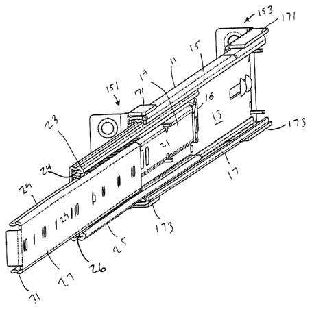
Fig. 1 illustrates a telescopic drawer slide in accordance with the aspects of
the present
invention. The drawer slide includes an outer member 11. The outer member has
a substantially
elongate web 13, an upper bearing raceway 15, and a lower bearing raceway 17
along upper and
lower margins of the elongate web. The terms "upper", "lower", and other
directional terms are
used for convenience of description, in accordance with the usual mounting of
the slide to a
cabinet or the like.
Nestled within the outer slide member is an intermediate slide member 19. The
intermediate slide member has a longitudinal elongate web 21. The intermediate
slide member
has an upper outer bearing raceway 23, an upper inner bearing raceway 24, a
lower outer bearing
raceway 25, and a lower inner bearing raceway 26, also along the upper and
lower longitudinal
margins of the elongate web. Nestled within the bearing raceways of the
intermediate slide
member is an inner slide member 27. The inner slide member has an elongate web
29 also with
upper and lower bearing raceways 29, 31, respectively, along the margins of
the elongate web.
The slide members are longitudinally extendable with respect to one another.
The slide of FIG. 1 also includes latching tab 16 rotatably coupled to the
intermediate
drawer slide. The tab is moved over an emboss (not shown) on the outer slide,
and biased
-2-
CA 02431240 2003-06-04
WO 03/030685 PCT/US02/33405
downward by gravity thereby preventing the intermediate slide from closing
relative to the outer
slide. When the inner slide is closed, its bearing raceways engage the tab
moving it upward and
out of its locked position thereby once again allowing closure of the
intermediate slide with
respect to the outer slide.
FIG. 2 illustrates a cross-section of the drawer slide of FIG. 1. The drawer
slide includes
an outer slide member 41, an intermediate slide member 43, and an inner slide
member 45. Each
of the slide members has a respective vertical web 61,63,65 with bearing
raceways formed in the
upper and lower margins of the vertical web. The intermediate slide member is
largely nestled
within bearing raceways 51, 52 of the outer slide member, and the inner slide
member is largely
nestled within bearing raceways 55, 56 of the intermediate slide member.
As can be seen in FIG. 2, bearings 47 are disposed between the upper raceways
51 of the
outer slide member and upward facing upper raceways 53 of the intermediate
slide member, and
bearings 49 are also placed between downward facing upper raceways 55 of the
intermediate
slide member and upper raceways 57 of the inner slide member. Similarly, the
bearings are
disposed between the raceways of the frame of the lower bearing raceways of
the outer slide
member and the intermediate slide member, as well as the intermediate slide
member and the
inner slide member. The bearings slidably couple the slide members. Bearings
may be disposed
directly in the raceways, or may be disposed within a bearing spacer 48 or
retainer 58 within the
raceway, which serve to retain and properly space the bearings. In operation,
the bearings
also serve to transfer loads from the inner slide member to the intermediate
slide member, and
then to the outer slide member. A cross-section of the outer slide member is
illustrated in FIG.
3. The outer slide member has a vertical web 71, with an upper bearing raceway
73 along the
upper margin of the vertical web, and a lower bearing raceway 75 along the
lower margin of the
vertical web. In one embodiment, joggled offsets 77, 79 connect the vertical
web to the bearing
raceways. The offsets are in the same general direction in which the bearing
raceways extend
from the vertical web, and connect the central portion of the vertical web 71,
to respective end
portions 78, 80. The end portions 78, 80 are substantially parallel to the
central portion of the
vertical web 71. The offsets minimize bowing or warping of the slide member
when subjected
to vertical, horizontal, and/or torsional loads. In addition, the offsets
provide an additional
horizontal offset to the bearing raceways, which provides additional space for
mounting hardware
or other items between the webs of the outer and intermediate slide members.
The additional
space is useful, for example, in thin embodiments of the invention, and may be
varied to
accommodate clearance of specific hardware, such as particular size screws,
rivets, stand-offs,
pem-nuts, bayonets or other hardware known to those skilled in the art. In one
such thin
embodiment, a drawer slide with an envelope of .375 inch wide by 1.62 high was
formed.
FIG. 4 further illustrates the joggled offset of the outer slide, and also
illustrates a gusset
-3-
CA 02431240 2003-06-04
WO 03/030685 PCT/US02/33405
81 in the bearing raceway. The linear gusset runs substantially along the
length of the bearing
raceway. As illustrated, the gusset is substantially along a center line of
the bearing raceway.
The linear gusset serves to constrain movement, particularly lateral movement,
of bearings placed
in the raceway. In one embodiment the gusset is formed by pressing on the
surface of the bearing
raceway. This pressing action serves to provide a cold reduced work hardened
surface for
contacting the ball bearings, and this surface limits the Brunelling effects.
In one embodiment the linear gusset allows for a 65 degree contact angle for a
ball bearing
placed in the raceway. In addition, the radius of the linear gusset provides
clearance to allow for
point contact of, in one embodiment, a three millimeter size ball bearing.
In one embodiment, integral stops are formed into the upper and lower bearing
raceways.
The stops provide contact with and contain the bearings or bearing spacers,
while maintaining
the material integrity of the outer member channel, and providing maximum
shear strength for
the formed stops. Such stops may be placed as desired to limit longitudinal
movement.
FIG. 5 illustrates a cross-section of the intermediate slide member. The
intermediate slide
member includes a substantially vertical web 91 with bearing raceways 93,95
along the upper
and lower margins of the vertical web. The vertical web includes a central
portion 97, inset from
the upper portion 96 and lower portion 98 by two jogs 101,103 in the vertical
web. The inset
central portion allows for increased distance between the vertical web of the
intermediate slide
member and the vertical web of the outer slide member, as may be seen in FIG.
2. In one
embodiment, the central portion of the vertical web is offset sufficiently to
provide clearance for
a #8 screw. It will be appreciated that the design of the offset distance may
be varied to
accommodate specific mounting hardware. The inset also provides increased
rigidity of the slide
member to minimize torsional twisting and bow along the length of the slide
member.
In one embodiment, the ball races are formed by bending a portion of a slide
member to
form a largely doubled-over section approximately at right angles to the
vertical web. The
doubled-over section forms, using the upper bearing raceways as an example, an
intermediate
to outer member bearing raceway 105 and an intermediate to inner member
bearing raceway 107.
The two raceways are offset vertically. The vertical offset allows the
material forming the
raceways to provide substantially constant material thickness along the
bearing raceways. The
constant material thickness allows for maintenance of slide member material
integrity and
improved load bearing capacity. Connecting the two raceways is an angled
transition 109
providing for increased rigidity of the member along the ball races.
A cross-section of the inner slider member is illustrated in FIG. 6. The inner
slide member
has a vertical web 111 with upper and lower ball bearing raceways 113,115
along the upper and
lower margins, respectively, of the vertical web. The raceways are offset from
the web a
sufficient distance to provide clearance for mounting hardware used to mount
the inner slide
-4-
CA 02431240 2003-06-04
WO 03/030685 PCT/US02/33405
member to a drawer or equipment. The width of the vertical web is also
sufficient to allow for
lancing, forming tabs, and the like for use in mounting.
Returning to the slide of FIG. 1, it may be seen that mounting brackets are
coupled to the
slide. More specifically, in FIG. 1 a front mounting bracket 151 is coupled
approximate a front
edge of the outer slide member, and a rear mounting bracket 153 is coupled
approximate a rear
edge of the slide member. As illustrated in FIG. 7, the mounting bracket
includes a face plate
161. The face plate is adapted to be placed with one side 163 against the
outer slide member.
Mounting holes 165 extend through the face plate to allow mounting screws,
hardware and the
like to secure the face plate, and thereby the mounting bracket, to the outer
slide member.
As illustrated in FIG. 7, the mounting holes are arranged in triangular
patterns
approximate the forward and rearward edges of the face plate. The placement of
the holes in such
a pattern allows the mounting bracket to be more easily used with slides of
varying profiles,
particularly varying heights. In one embodiment, the holes are extruded, with
an extrusion 167
extending outwards from face plate away from the side of the face plate
mounted to the outer
slide member. The extrusions, in one embodiment, are threaded, thereby
allowing for increased
ease of use, and perhaps more importantly decreased hardware requirements, for
mounting the
face plate to the outer slide member.
The mounting bracket also include wrapping flanges 171,173 (seen also in FIG.
1)
extending along the top and bottom edges of the face plate. The wrapping
flanges extend in the
direction of the slide. The wrapping flanges are adapted to hug or receive the
outer slide member,
as may be seen in FIG. 1. The wrapping flanges thereby provide increased
support to the slide
member to which the mounting bracket is mated, in this example the outer slide
member.
Returning to FIG. 7, the mounting bracket also includes a front flange 181.
The front
flange extends from what for convenience will be termed the front of the face
plate. As will be
evident, if not so already, the mounting bracket may be mounted to the slide
with either the front
of the face plate in the direction of the front of the slide or the rear of
the slide. The front flange
extends in the direction away from the slide, when the mounting bracket is
mounted to the slide.
Three holes 183 are placed in the front flange. The holes are placed in a
line, and are
suitable for receiving bolts, pins, and other hardware for attaching the
mounting brackets to face
frames, vertical beams, racks, and similar structures. As may be seen in FIG.
1, the front flange
extends away from the slide, and is largely perpendicular to both the
direction of extension of the
slide and a plane formed by the vertical webs.
The holes in the front flange, in one embodiment, are embossed, protruding
towards the
front surface of the front flange (with "front" as considered with respect to
the discussion of the
front flange). The holes therefore allow for more easier seating of, for
example, pins placed from
the rear of the front flange through to the front surface of the front flange.
Moreover, for racks
-5-
CA 02431240 2003-06-04
WO 03/030685 PCT/US02/33405
190 with square holes 191, or sufficiently large round holes 193, as may be
seen in FIG. 8, the
extending protrusions on the front of the front flange allow more readily for
seating of the flange
in position on the rack during installation.
In one embodiment disposable pins 201 are also provided to increase ease of
installation.
As may be seen in FIGS. 8 and 9, the pins are substantially cylindrical with a
bulge 203 about the
middle of the pin. The bulge is sized with respect to the holes in the front
flange to provide a
tight fit, allowing for the pins to be snapped into the holes. The diameter of
the forward edge of
the pin is sized relative to the holes, or cutouts, in the racks such that the
pins may be placed in
the cutouts, thereby supporting the mounting bracket, and slide, during
installation. After
installation is complete and mounting hardware is positioned and secure, the
pins may be
removed and disposed.
In one embodiment, the pins include a slot 205 about the middle of the pin.
The slot
creates a weakened area in the pin about the front flange. This weakened area,
when additional
force is provided to lever the pin about the front flange, is designed in one
embodiment to break
and free the pin from the flange when no longer needed. In another embodiment,
force is applied
to the front of the pin, releasing the pin from engagement with the front
flange when the pin is
no longer needed.
The present invention therefore provides a thin drawer slide, and accompanying
useful
related items. Although the invention has been described with respect to
certain embodiments,
it should be realized that the invention may be practiced other than as
specifically described.
Accordingly, the invention should be viewed as the claims supported by this
specification and
their equivalents.
-6-