Note: Descriptions are shown in the official language in which they were submitted.
CA 02431658 2003-06-09
WO 02/058505 PCT/US02/01975
APPLICATOR FOR APPLYING LIQUID PRODUCTS TO HAIR
Field of the Invention
The present invention relates to an applicator for applying liquid products,
such as
dye or coloring, to the hair. The applicator can be used in conjunction with a
manually
squeezed or aerosol propelled dispensing type container or other type
dispensing devices.
Description of the Prior Art
A variety of devices for applying hair treatment products currently exist.
Many such
devices or applicator assemblies have applicators that include tines that are
too narrow and
have insufficient surface area to distribute product evenly throughout the
hair. Other
applicators have comb tines which are too large and too wide making it
difficult to get the
comb through the hair and also causing discomfort to the end user. Existing
applicators also
have difficulty in getting product to the hair roots because the upper section
of the tines can
be too large, thus not allowing the comb to penetrate the hair and get to the
roots. Some
applicators have too many tines or have tines which are positioned too close
together.
However, one commonality among all the current applicators is the mess
suffered by the end
users and their environment by product being dropped or "flicked" off of the
device in use
as a result of the problems associated with the shapes described above.
A desirable applicator would be one that evenly delivers product to the
surface of the
hair, the roots of the hair and the bulk of the hair. The surface of the hair
is the hair that is
most likely to be seen or that hair which is in plain view. Delivering product
to the surface
of the hair is critical to the consumer because it allows them to see what
they have coated.
The root of the hair is that length of the hair closest to the scalp and is
normally up to about
one inch from the scalp. Delivery of the product to the root of the hair is
important
aesthetically to the consumer. Lastly, the bulk of the hair is that area
between the root and
the surface. Product delivery to the bulk of the hair is important because the
product acts as
a lubricant when combed through the hair which adds to the comfort during
application, and
consistent coloration throughout the hair is preferred by the consumer.
1
CA 02431658 2003-10-20
Summary of the Invention
An object of the present invention is to provide an applicator for applying
liquid
products to hair. In accordance with an aspect of the present invention, there
is provided
an applicator assembly (10) for applying liquid to hair, said applicator
assembly
comprising an applicator (20) having a base (30) comprising a liquid
distribution cavity (132), a
plurality of tines (50) each having a longitudinal length (L) extending from
said base, wherein at
least one of said tines further comprise a tip (64) having an end located
distally from said base,
and an aperture (62, 68) in fluid communication with said liquid distribution
cavity, characterized
in that at least one of said tines further comprises an enlarged fin (54)
section adjacent to said
base, said fin section extending along said tine less than half-way upward
between said base and
the distal end of said tip.
In accordance with another aspect of the invention, there is provided an
applicator assembly (10) for applying liquid to hair, said applicator assembly
comprising an applicator (20) having a base (30) comprising a liquid
distribution cavity (132), a
plurality of tines (50) each having a longitudinal length (L) extending from
said base, wherein at
least one of said tines further comprise a tip (64) having an end located
distally from said base,
and an aperture (62, 68) in fluid communication with said liquid distribution
cavity, characterized
in that said aperture comprises at least two spaced dispensing apertures and
at least two aperture
channels (170), each aperture channel providing fluid communication between
one of said
dispensing apertures and said distribution cavity.
In accordance with another aspect of the invention, there is provided an
applicator assembly (10) for applying liquid to hair, said applicator assembly
comprising an applicator (20) having a base (30) comprising a liquid
distribution cavity (132), a
plurality of tines (50) each having a longitudinal length (L) extending from
said base, wherein at
least one of said tines further comprise a tip (64) having an end located
distally from said base,
and an aperture (62, 68) in fluid communication with said liquid distribution
cavity, characterized
in that at least one of said tines further comprises an enlarged fin (54)
section adjacent to said
base, and at least one of said tines further comprising said enlarged fin
section is configured to
provide a substantially rigid lower section (386) and a substantially flexible
upper section (384)
adjacent said tip.
2
CA 02431658 2003-10-20
In an exemplary embodiment of the invention, an applicator assembly has an
applicator which comprises a base and a plurality of tines. The base of the
applicator can be
connected to an applicator housing by a skirt extending from the base.
Typically, the
applicator housing would connect to a manually squeezed or aerosol propelled
dispensing
type container or other type of liquid source or dispensing device. The
plurality of tines
extend outwardly on the opposite side of the base from the skirt. The tines
also have a fin
shaped bottom portion and a narrowed upper portion. The upper portion of the
tine may
have a lower aperture that is substantially at an intermediate point of the
tine and/or a tip
aperture adjacent to the distal end of the tine. The base may also have one or
more apertures
between adjacent tines. The base, tines and apertures of the applicator are
designed to
deliver even flow of product to the surface, root, and bulk of the consumer's
hair. The tines
may be partially flexible and at least some of the tines comprise a fluid
pathway for delivery
of product to the apertures.
Other advantages and novel features of the present invention will become
apparent to
those skilled in the art from the following detailed description, which simply
illustrates
various modes contemplated for carrying out the invention. As will be
realized, the
invention is capable of other different obvious aspects, all without departing
from the
invention. Accordingly, the drawings and descriptions are illustrative in
nature and not
restrictive.
Brief Description of the Drawings
While the specification concludes with claims particularly pointing out and
distinctly
claiming the present invention it is believed that the same will be better
understood from the
following description, taken in conjunction with the accompanying drawings, in
which:
Fig. I depicts a perspective view of an exemplary embodiment of an applicator
assembly made in accordance with the present invention;
Fig. IA depicts a partial exploded view of the applicator assembly in Fig. 1;
Fig. I B depicts a partial enlarged cross sectional view of the applicator
assembly in
Fig. 1;
2a
CA 02431658 2003-06-09
WO 02/058505 PCT/US02/01975
Fig. 2 depicts a perspective view of an exemplary embodiment of an applicator,
made in accordance with the present invention;
Fig. 3 depicts an end elevational view of the applicator in Fig. 2;
Fig. 3A depicts partial schematic views of various exemplary embodiments of
tines
of the applicator in Fig. 2 made in accordance with the present invention;
Fig. 4 depicts a partial top planar view of the applicator in Fig. 2;
Fig. 5 depicts a cross sectional view of an exemplary embodiment of another
applicator of the present invention;
Fig. 6 depicts a partial schematic view of a consumer;
Fig. 6A depicts a partial cross sectional view of a consumer's hair;
Fig. 7 depicts an enlarged partial view of an exemplary embodiment of an
applicator
assembly in use according to the present invention;
Fig. 8 depicts a cross sectional view similar to that of Fig. 5 of an
alternative
embodiment of the tines in an applicator made in accordance with the present
invention;
Fig. 9 depicts a top planar view of an applicator of the present invention
including
tines as depicted in Fig. 8;
Fig. 10 depicts an enlarged, partially cut-out top plan view of a tine of Fig.
8; and
Fig. 11 depicts an end elevational view of the applicator of Fig. 2 in another
exemplary embodiment of an applicator in accordance with the present
invention.
Detailed Description of Exemplary Embodiments
Reference will now be made in detail to various exemplary embodiments of the
invention, several of which are also illustrated in the accompanying drawings,
wherein like
numerals indicate the same elements throughout the views, and numbers with the
same final
two digits indicate corresponding elements among embodiments.
Fig. 1 depicts a non-limiting exemplary embodiment of an applicator assembly
10
wherein an applicator 20 is assembled with an applicator housing 14 and a
container 11 in
the general form of a comb-like device for applying liquids to the hair of a
consumer. It is
contemplated that the applicator assembly 10 can be provided in a variety of
forms and
structures wherein a source of product to be applied is placed in fluid
communication with
the applicator. While the combination of an applicator with a housing (e.g.
14) and a hand
held container (e.g. 11) may be used as illustrated, other arrangements may
equally be
3
CA 02431658 2003-06-09
WO 02/058505 PCT/US02/01975
substituted as well. For example, the applicator 20 may be connected to, or in
fluid
communication with, a hose (not shown) or other such delivery device.
Fig. 1A shows the applicator 20 detached from the applicator housing 14 and
the
applicator housing 14 detached from the container 11. Although many attachment
arrangements can be utilized, for ease and strength of assembly, the
applicator housing 14
may have a screw fitting 18 at its lower end to attach to the container's
screw fitting 12. In
such an example, both the container 11 and the applicator housing 14 may be
joined with
lugs, 13 and 19 respectively, which might snap into locking engagement with
one another
when the applicator housing 14 has been fully attached to (e.g., screwed into)
the container
11.
As also shown in Fig. 1A, applicator 20 has a skirt 40 which can be utilized
to secure
the attachment of the applicator 20 to the housing 14. As seen in Fig. 1 B,
once the applicator
is attached to the device housing 14, a fluid reservoir 16 is defined which
allows fluid
communication, depicted by a crosshatch pattern, between the applicator
housing 14 and the
15 applicator 20. The fluid flow will be discussed in greater detail later.
It may be appreciated that multiple applications of products with varying
compositions may require using the housing 14 repeatedly with a variety of
containers 11 to
achieve the consumer's desired shade of hair colorant.
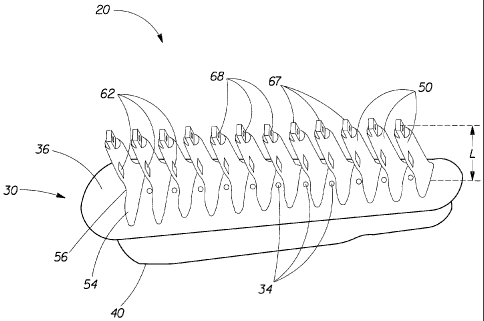
Fig. 2 depicts a non-limiting exemplary embodiment of an applicator 20 in the
20 general form of a comb-like device for applying liquids to the hair of a
consumer. The
illustrated applicator 20 has a base 30 with a skirt 40 extending downwardly
therefrom and a
plurality of tines 50 extending upwardly from the base 30. Fig. 2 further
shows that the base
has base apertures 34 and an outer surface 36. Although the physical
characteristics of
the tines 50 may vary in the many embodiments of the present invention, the
tines 50
25 similarly extend outwardly from the surface 36 of the base 30 and are
generally cone shaped
to facilitate ease of combing the applicator 20 through the hair of a
consumer. The plurality
of tines 50 each may have a bridge 67, an upper aperture 68, lower apertures
62, and a fin
shaped bottom portion 54 with a shoulder portion 56 defining the upper or
distal portions of
the fin 54.
30 Fig. 3 shows a non-limiting exemplary embodiment of a tine 50, along with
the base
30 of an applicator 20, in greater detail. Each tine 50 of this example
includes a fin 54
4
CA 02431658 2003-06-09
WO 02/058505 PCT/US02/01975
adjacent its proximal end that is connected adjacent to the outer surface 36
of the base 30,
and an upper portion 58. The top part of the upper portion 58 of the tine 50
will be described
as tip 64 and comprises the upper end of the upper portion 58, and might
extend down near
the fin 54 but usually will not include the part of the upper portion
connected to the fin 54.
The tine 50 has a height or longitudinal length "L" measured from the
lowermost point of the
fin 54 to the uppermost point, or a distal end 65, of the tine tip 64. The
tine 50 also has a
width "W" measured at 50% of the overall length L of the tine 50. The
relevance of the
length L and the width W dimensions will be discussed in greater detail below.
The fin
section 54 has a height "hf" as measured from the lowermost to higher most
point of the fin
54. The fin also has a width W, measured across the lowermost points of fin
54. The fin
width Wf may vary from tine to tine in a single embodiment and certainly may
vary among
embodiments. The upper portion 58 of the tine 50 has a height "hu" as measured
at the
higher most point of the fin 54 to the distal end 65 of the tine tip 64. The
upper portion 58
also has a width W, measured at the distal end 65 of the tine tip 64. The
heights and widths
may vary from tine to tine in a single embodiment.
As seen in Fig. 3, the fin 54 generally provides a wider base section of the
tine 50
which tapers in either a radius or natural line to the upper portion 58 of the
tine 50. For
example, the fin 54 may end at a point where the smallest radius of the
tapering section
exists. However, other embodiments may not have a radius, rather, they may be
of a more
conical shape having single or multiple angles rather than a true radius, or
they may be of
some other geometrical configuration or combination of geometrical
configurations, as
would be obvious to one skilled in the art. The fin 54 generally includes a
shoulder portion
56, although the shape, size and prominence of such shoulder can vary, as will
be explained.
As will be appreciated, interface 57 between the shoulder 56 of the fin 54 and
upper portion
58 can also vary in configuration and prominence, and may comprise a radius,
an angle, or a
smooth transition, or any combination of geometries.
Figs. 3A. shows different embodiments of the tine 50 of the current invention.
Each
embodiment shows the fin 54 and the upper portion 58. The fin 54, in these
embodiments,
extends to a length of no more than 50% of the overall length of the tine 50.
Embodiment A,
of Fig. 3A, shows a fin 54 that is almost 50% of the overall length of the
tine 50 and that has
a well defined or more visually prominent shoulder 56 located near its upper
end and having
5
CA 02431658 2003-06-09
WO 02/058505 PCT/US02/01975
a substantially horizontal component. Embodiment B shows a fin 54 that is also
almost 50%
of the overall length of the tine 50, but this fin 54 has a less defined large
and gently curved
shoulder 56. Embodiment C shows a fin 54 that is only about 20% of the overall
length of
the tine 50 and again that has a well defined shoulder 56. Compare these to
the tine 150
depicted in Fig. 5, wherein the fin 154 is about 35% of the overall length of
the tine 150, and
the shoulder is conically shaped but less prominent visually than embodiment A
or C of Fig.
3A. In this example, the interface 157 of shoulder 156 with the upper portion
158 comprises
a ring formed at the junction of the generally conically surfaces between the
upper portion
158 and the fin 154. Note, where embodiments of the tine are unclear as to
where the
interface between the shoulder of the fin and the upper portion of the tine is
located, the fin
may be defined as starting where the tine increases in width by greater than
20% of the
width, e.g. W in Fig. 3. It is contemplated that the interface will generally
be defined by a
change in angle, a radius, or other junction or intersection between the
shoulder and the
upper portion of a tine.
i5 The fin 54 adds structural stability and rigidity to the tine 50 and also
may help
facilitate separation of hairs as they pass across the applicator 20. The fin
54 can also help
distribute liquid product in use and prevent product buildup or collection --
which can lead to
"flicking" problems. The shoulder portion 56 can be provided with a
substantially horizontal
component which may also help to minimize the flicking problem.
Also, as shown in Fig. 3, at least some of the tines 50 include a lower
aperture 62 at
about the mid point and/or an upper aperture 68 adjacent to the tip 64. The
upper portion 58
of the tine 50 may have a plurality of lower apertures 62 located at about a
mid-point
between the distal end 65 of the tip 64 and the shoulder 56 and having a
dispensing angle
oriented to direct liquid outward and substantially perpendicular or normal to
the length L of
the tine 50. One lower aperture 62 would typically be on each of the
oppositely disposed
elongated sides of the elliptical cone shaped tine 50, that is, on the side of
the tine 50 where
the width W is measured and generally directed toward the space between
adjacent tines 50.
Also, at its tip 64, the tine 50 has an upper aperture 68 and may also have a
flange or bridge
67. The upper aperture 68 provides a liquid outlet having a dispensing angle
directed
substantially parallel to the length L. In this particular example, the upper
aperture 68 is also
located generally along the center line C of the tine 50, although its
location could be varied
6
CA 02431658 2003-06-09
WO 02/058505 PCT/US02/01975
widely. The bridge 67 is illustrated with a width W,, and is defined by any
portion of the tine
50 that extends beyond the upper aperture 68. The bridge 67 can help to divert
flow in a
radially outward direction, as seen in Fig. 7, from the upper aperture 68.
Fig. 4 discloses one embodiment of an applicator 20 from a partial top planar
view.
Each tine 50 has a thickness T measured across its upper portion 58 just above
its fin 54 and
adjacent the width W. Each of the tines 50 are separated by a distance D from
tine center to
tine center. The further relevance of the thickness T and the distance D will
also be
discussed in greater detail below. The base 30 might also have dispersing
apertures 34
between some or all of the adjacent tines 50. It should be understood that
these base
apertures 34, their number, size and location could vary among applications.
In some
situations, they might not be present at all. Also shown in Fig. 4 is the
bridge 67 and the
upper aperture 68.
As shown in Fig. 3, the lower apertures 62 might be staggered or located off
center of
the respective side of the tine 50 and positioned toward opposite narrow ends,
that is, toward
opposite sides of the tine 50 where the thickness (e.g. T in Fig. 4) is
measured. Molding
manufacturing, as known and as may be tuned by one skilled in the art, may be
simplified by
having staggered apertures because the pins used to make the apertures on each
side of the
tine 50 do not interfere with each other.
Fig. 5 shows another non-limiting exemplary embodiment of a tine 150, along
with
the base 130 having a skirt 140, in cross-section. The base 130 might also be
provided with
an elongated inner surface 138. The skirt 140 extends downwardly, and slightly
recessed
within the perimeter of an inner surface 138 and is offset inwardly of the
perimeter of the
base 130 to allow the applicator 120 to seat with an applicator housing. The
inner surface
138 and the skirt 140 generally define a liquid distribution cavity 132.
The base 130 also has a outer surface 136. In one embodiment, the outer
surface 136
may be convex. Tines 150 extend upwardly from the outer surface 136. The shape
of the
tines 150 is generally like an elliptical cone, as seen in Fig. 4, or
triangular, as seen in Fig. 3,
although the shape of tines for any particular application could vary widely.
The position of
the tines 150 on the base 130 could be random, staggered, or arranged in a
single line for
application of liquid such as hair color, conditioner or other treatment in a
combing-like
manner.
7
CA 02431658 2003-06-09
WO 02/058505 PCT/US02/01975
Also shown in Fig. 5, at least some of the tines 150 of applicator 120, which
include a
lower aperture (e.g. 62 in Fig. 3) and/or an upper aperture 168 from which
fluid may be
dispensed, will include one or more channels 170 that may be tapered or
slightly cone shaped
which extend from adjacent the inner surface 138 to at least one such
aperture. In this
illustrated example, the upper aperture 168 is the outlet end of the channel
170 which
provides fluid communication from the base cavity 132 to the upper aperture
168. At the
inner surface 138 of the base 130 the channel 170 has a width W,
In some embodiments of the invention, the lower aperture and the upper
aperture
may have a dispensing outlet area which are approximately equal. The term
"area" is used
here to accommodate dispensing apertures of all shapes and types, including
embodiments
allowing for the apertures to be round, slotted, square, slit type, always-
open bores, self-
sealing openings, or of any other manufacturable shape or method. It should be
noted,
however, that the base apertures might advantageously be about %2 (.5) to
about 3/4 (.75) of
the area or size of the lower aperture or of the upper aperture to provide
delivery of a proper
ratio of product through each aperture during use, thereby providing a more
predictable
and/or even coating of the product. Also note that the base apertures, as seen
in Fig. 4,
extend through the base, that is, they extend from the base inner surface to
the base outer
surface. Therefore, the base apertures are in direct fluid communication with
the fluid
reservoir.
To illustrate the use of the applicator, in accordance with the invention,
providing a
more predictable and/or even coating of the product consider Figs. 6, 6A, and
7. Fig. 6
schematically depicts a consumer 90. The consumer's hair 92 that is most
likely seen by the
consumer 90 and others is called the surface 93. However, whether because the
consumer 90
wears a different hair style or because the hair grows or just because of
consumer preference,
the hair surface 93 is not the only area needed to be treated. As seen in Fig.
6A, typically,
the consumer 90 expects a predictable and/or even coating of the product to
the surface 93,
the roots 94, and the bulk 95 of the hair 92, without any negative impact to
the scalp 96. The
roots 94 of the hair 92 are that length of hair 92 closest to the scalp 96 and
is normally
measured from the scalp 96 to about one inch (25 mm) in length. The bulk 95 of
the hair 92
is that area of hair 92 between the root 94 and the surface 93.
8
CA 02431658 2003-06-09
WO 02/058505 PCT/US02/01975
The applicator of the current invention provides the improved coating and
comfort
desired by consumers. For example, as seen in the embodiment of Fig. 1 and
depicted in Fig.
7, the product delivered to the base apertures 34 coat the surface 93 of the
hair 92 allowing
the consumer 90 to see where the product has been applied, thus allowing a
more even
s application of the product. The product delivered by the upper apertures 68
applies product
to the roots 94 of the hair 92 for a complete coloring. Further, the product
dispensed through
the lower apertures 62 also provides good lubrication to the tines 50 allowing
for easy
movement of the applicator 20 through the bulk 95 of the hair 92. Other
embodiments of the
current invention may include arrangements having only lower apertures and
base apertures,
having only upper apertures and base apertures, and having only upper
apertures and lower
apertures. Other embodiments may also use any variety of aperture sizes.
Fig. 4 shows the tines 50 as being separated by a predetermined distance D
that might
be about 1 to 1.5 times the width W of each individual tine. In one exemplary
embodiment
of the invention having a comb-like configuration, the width W of the tine 50
might range
from about 2.8 mm to about 5.7 mm and the distance D could range from 2.8 mm
to 8.5 mm.
The thickness T, of the tines 50 might range from about 1.3 mm to about 2.7
mm.
Other dimensions are shown in Fig. 3. For example, the width Wf of the tines
50 at
the fin 54 that is adjacent to the inner surface 38 of the base 30 might range
from about 8 mm
to about 16 mm, and the width W,, of the tines 50 at the distal end of the tip
64 might range in
width from about 1.3 mm to about 2.7 mm. Moreover, the total length L of the
tines 50
might range from about 10 mm to about 20 mm, wherein the upper portion 58,
defined by
distance h, might range in length from about 5.1 mm to about 16.0 mm, with the
fin 54,
defined by distance hf ranging from about 2.0 mm to about 9.9 mm. The distance
hf will be
less than the distance hu and may be a minimum of 20% of the tine length L.
Also, as seen in
Fig. 5, the channel 70 may preferably range, at the tine tip 64, or the upper
aperture 68
diameter, from about 0.8 mm to about 1.7 mm, and, at the inner surface 138,
the channel 70
may preferably range from about 1.1 mm to about 2.3 mm. The spacings and
ranges could
vary by particular application, product to be dispensed, or preferences as
will be understood
by one skilled in the art.
Fig. 8 - Fig. 10 show different embodiments of the tines 250 in an applicator
220
made in accordance herewith. As viewed in Fig. 8, the tine 250 has multiple
channels;
9
CA 02431658 2003-06-09
WO 02/058505 PCT/US02/01975
particularly, a first channel 273 and a second channel 274. In one embodiment,
these
channels are tapered from wider to narrower as they extend toward the tip 264.
This allows,
for example, ease in removing the molding pins used to form the channels
during injection
molding manufacturing. The tip 264 is substantially the same configuration for
the tine 250
as in previous embodiments discussed. The first channel 273 extends from the
inner surface
238 to the upper aperture 268 and provides fluid communication with the base
cavity 232
similar to previous embodiments discussed. A second channel 274 runs adjacent
to the first
channel 273. The second channel 274 extends from the inner surface 238 to the
lower
aperture 262. However, instead of a lower aperture having a dispensing angle
directed from
the side of the tine, the lower aperture 262 has a dispensing angle directed
upwardly and is
merely a continuation of the second channel 274. This can make manufacturing
easier
because, as known by those skilled in the art, pins may be used instead of
shut-offs. Shut-
offs create metal to metal contact which can cause increased cost and
decreased mold life.
Pins tend to wear less because the metal to metal contact is minimized.
Typically, pins are
also easier to replace and more readily available.
Fig. 9 shows a top plan view of such a dual channel embodiment of the
applicator
220. The lower apertures 262 and the upper apertures 268 are on alternate
sides of each
adjacent tine 250. By this staggered method, the lower aperture 262 on every
other tine 250
is directed toward the leading edge of the tine 250. The leading edge of the
tine 250 is the
surface of the tine 250 pointed in the direction of the combing or movement of
the applicator
220. Thus, fluid or product from the lower aperture 262 is also directed
toward the leading
edge on every other tine 250. This staggered configuration allows for multiple
direction
application and consistent flow of product no matter which direction the
consumer combs
their hair. Since the lower aperture lubricates the bulk of the hair, the
comfort to the
consumer when combing is increased by the staggered design.
Fig. 10 illustrates an enlarged view of detail "B" from Fig. 9. As shown in
Fig. 10,
and as may be seen by comparison in Fig. 7, the bridge 267 increases the
comfort to the scalp
96 of the consumer while directing product flow in a more horizontal direction
toward the
roots 94 instead of directly into the scalp 96. The bridge 267 is an arch-like
extension
beyond the upper aperture268. The upper aperture 268 may be made by piercing a
wire
through the tines 250 after the applicator is formed or by using shut-offs as
known to those
CA 02431658 2003-06-09
WO 02/058505 PCT/US02/01975
skilled in the art. As fluid is delivered by the upper aperture 268, the
bridge 267 deflects the
fluid from its longitudinal flow along the length of the tine 250 to a
direction somewhat
perpendicular to the length. Thus, the flow is directed toward the roots 94 of
the consumer's
hair 92 instead of toward the consumer's scalp 96. The bridge 267, also has
rounded corners
(also best depicted as 67 in Fig. 7) that increases the comfort to the scalp
96 of the consumer.
Thus Fig. 7 shows how, in various embodiments having a bridge, the bridge
disrupts fluid
flow from the upper aperture. As product exits the upper aperture, the bridge,
as stated,
disrupts the flow and redirects the flow substantially perpendicular to the
tine length. Again,
this disruption allows more product to flow to the root of the hair and less
product is
directed to the scalp of the consumer.
Dimensionally, and as seen in Fig. 8, the total length L of the tines 250 in a
comb-like
arrangement may range from about 10 mm to about 20 mm, wherein the upper
portion 258
might range in length from about 5.1 mm to about 16.0 mm. Other dimensions
might be
similar to those disclosed with previous embodiments.
is In yet an additional embodiment of the current invention, the fin portion
of the tines
may generally be more rigid in nature than the tip of the upper portion. In
particular, the fin
may be formed of stronger or more rigid material, reinforced, or made thicker
than the
otherwise more compliant, compressible, thinner, less strong and substantially
more flexible
tip, by structural design. Accordingly, the fin of the tine may be
substantially rigid to
provide support to the flexible tip and may facilitate application of the
product.
Fig. 11 depicts such an embodiment of the present invention having a rigid
section
386 and a flexible section 384. The place on a tine 350 where the rigid
section 386 stops and
the flexible section 384 begins is called an interface 382. The flexible upper
section 384 of
the tine 350 is illustrated as having a flexible length L,, and may be
generally soft to the
touch, compliant and compressible. The flexible length L, may vary in location
in different
embodiments but will generally be where the interface 382 is above the fin 354
and, in
embodiments having a bridge 367, below the bridge 367. In a comb-like example,
the
flexible length L, might range from about 3.3 mm to about 6.7 mm, and the
balance of the
tine 350 would be considered the rigid section 386. The characteristics of
such embodiments
may provide the tine 350 with a unique combination of good scalp contact while
also
providing a pleasant feel upon contact.
11
CA 02431658 2003-06-09
WO 02/058505 PCT/US02/01975
Additionally, because the flexible section 384 facilitates intimate contact
with the
scalp during use, it may also help optimally disperse the product and optimize
the amount of
product used by acting as a valving feature. The substantially flexible
section may increase
the effective outlet opening size of said apertures to a predetermined size
during application.
This is especially useful if the upper aperture 368 is a slit or self-sealing
opening. Contact of
the soft bridge 367 with the consumer's scalp will cause the flexible section
384 of the tine
350 to flex, allowing unobstructed flow of product through the open valve or
upper aperture
368. Once the flexible section 384 loses contact with the scalp, the valve
will close as the
flexible section 384 returns to its normal position.
In some embodiments of the invention, as shown in Fig. 11, the tines 350 could
be
more conveniently or simply manufactured from different material constituents,
such as a
more rigid material for the rigid section 386, and a relatively soft,
compliant and
compressible material for the flexible section 384. Such a multiple material
design may give
the broadest range of structural features that would need to be taken into
account such as wall
thickness, length, width, and geometric configuration. In other embodiments,
it is feasible
to manufacture the tines 350 from a single material such as polypropylene,
polyethylene,
thermoplastic elastomer or other material having the characteristics of a
rigid section 386
adjacent the base 330 and a flexible section 384 adjacent to tip 364 as a
result of the
manufacturing process of locally controlling heat, pressure and other such
variables known
to those skilled in the art.
In a non-limiting exemplary embodiment of the present invention that may apply
to
single channel, dual channel or any other tine configuration, the tines could
be manufactured
using a two-shot injection molding manufacturing process. In particular, the
fin of the tines
might be manufactured as a single integrated component with the base due to
the desired
substantially rigid nature of both structures. Manufacturing this integrated
component might
comprise the first shot in the two-shot manufacturing process. A suitable
material may
include polypropylene SM-6150 such as available from Montell, although, other
thermoplastic materials such as polypropylene, polyethylene, polyester,
polycarbonate or
polyvinylchloride would also be suitable for this purpose. In an exemplary
device for scalp
applications, the selection of such a material may include materials having a
flexible
12
CA 02431658 2008-11-05
modulus of about 50,000 psi to about 200,000 psi, wherein flexible modulus is
defined as the
ratio of stress to corresponding strain within an elastic limit.
The second shot of the contemplated two-shot manufacturing process might then
comprise molding of a flexible material over the tine rigid section to create
the soft,
s compliant and compressible flexible section. Although the flexible material
could be formed
to the base in a variety of ways, in one embodiment of the invention, the
flexible tine
material is chemically bonded over the rigid section of the tine and the
entire outer surface of
the base due to the compatibility of the materials selected. Put another way,
the chemical
properties of properly selected constituent materials can allow the materials
to be selectively
bonded in a chemical process. Other methods of bonding the multiple-layers may
include
the use of adhesives or other alternative mechanical processes. As a result,
the applicator is
manufactured with a rigid material and then laminated or shrouded with a soft
to the touch,
compliant and compressible material that extends and creates the tip of the
tine and perhaps
extends over the fin and base outer surface.
The flexible tine can be manufactured using a soft, compliant and compressible
material such as Versaflex ST1025-X, as available from GLS Corporation,
however, it
should also be recognized that nearly any thermoplastic elastomer, santoprene
rubber or
other material having similar characteristics could be substituted. Moreover,
the selection of
the materials should be made for ease of use and comfort to the consumer as
well as for
manufacturability. For example, a durometer hardness of between about 50 Shore
A to about
100 Shore A may be desired wherein the durometer hardness is measured based on
initial
indentation of the material or indentation after a specified period of time.
In an alternate
embodiment for the applicator, the outer tine material could also be treated
or coated with a
slip agent to reduce the coefficient of friction such that the tines could be
readily combed
through hair and on the scalp.
Note that not all tines need to dispense fluid to the hair. Some could be for
product
"working" while others may be for massaging or other mechanical activities
such as support
for the tine structure, spacing for proper volume of product delivery, and
protecting soft tip
tines from being over flexed such that they fail to deliver product or break.
A "working"
tine, for example, merely helps to move the fluid through the hair during the
combing action
or may just improve the combing allowing the consumer more control of the
hair.
13
CA 02431658 2003-06-09
WO 02/058505 PCT/US02/01975
Messaging tines may be added to improve the comfort to the consumer, for
instance, by
being slightly longer and having a flexible tip. Also, not all tines need be
the same length.
Some might be shorter and less flexible for messaging, product working, skin
treatment or
support.
Having shown and described various embodiments of the present invention,
further
adaptations of the of the present invention as described herein can be
accomplished by
appropriate modifications by one of ordinary skill in the art without
departing from the scope
of the present invention. Several of these potential modifications and
alternatives have been
mentioned, and others will be apparent to those skilled in the art. For
example, while
exemplary embodiments of the inventive system have been discussed for
illustrative
purposes, it should be understood that the elements described may be
constantly updated and
improved by technological advances. Accordingly, the scope of the present
invention should
be considered in terms of the following claims and is understood not to be
limited to the
details of structure, operation or process steps as shown and described in the
specification
and drawings.
14