Language selection

Search

Patent 2431931 Summary

Third-party information liability

Some of the information on this Web page has been provided by external sources. The Government of Canada is not responsible for the accuracy, reliability or currency of the information supplied by external sources. Users wishing to rely upon this information should consult directly with the source of the information. Content provided by external sources is not subject to official languages, privacy and accessibility requirements.

Claims and Abstract availability

Any discrepancies in the text and image of the Claims and Abstract are due to differing posting times. Text of the Claims and Abstract are posted:

  • At the time the application is open to public inspection;
  • At the time of issue of the patent (grant).
(12) Patent Application: (11) CA 2431931
(54) English Title: METHOD FOR SEALING OFF A GAP BETWEEN A THROTTLE VALVE PIVOTABLY MOUNTED IN A THROTTLE VALVE ASSEMBLY AND THROTTLE VALVE ASSEMBLY
(54) French Title: PROCEDE PERMETTANT D'ETANCHEIFIER UN ESPACE SITUE ENTRE UN PAPILLON DES GAZ MONTE PIVOTANT DANS UN CARTER ET LEDIT CARTER
Status: Deemed Abandoned and Beyond the Period of Reinstatement - Pending Response to Notice of Disregarded Communication
Bibliographic Data
(51) International Patent Classification (IPC):
  • F16K 1/226 (2006.01)
  • F2D 9/10 (2006.01)
(72) Inventors :
  • FLIEGNER, JORG (Germany)
  • KOHLEN, PETER (Germany)
(73) Owners :
  • SIEMENS AKTIENGESELLSCHAFT
(71) Applicants :
  • SIEMENS AKTIENGESELLSCHAFT (Germany)
(74) Agent: SMART & BIGGAR LP
(74) Associate agent:
(45) Issued:
(86) PCT Filing Date: 2001-12-12
(87) Open to Public Inspection: 2002-06-20
Availability of licence: N/A
Dedicated to the Public: N/A
(25) Language of filing: English

Patent Cooperation Treaty (PCT): Yes
(86) PCT Filing Number: PCT/DE2001/004667
(87) International Publication Number: DE2001004667
(85) National Entry: 2003-06-12

(30) Application Priority Data:
Application No. Country/Territory Date
100 62 447.2 (Germany) 2000-12-14
101 23 490.2 (Germany) 2001-05-15

Abstracts

English Abstract


The invention relates to a throttle valve connection (1), in which a liquid
sealing mass (7, 8) is exclusively applied to an adjoining zone of a tubular
housing (2) and a throttle valve (3), using a cannula (9). The sealing mass
(7, 8) reaches the zone between the tubular housing (2) and the throttle valve
(3) by capillary force and subsequently hardens. This prevents a wetting of
the surface of the throttle valve (3) by the sealing mass (7, 8).


French Abstract

Procédé qui consiste à déposer une masse d'étanchéité (7, 8) liquide dans un carter (1) de papillon des gaz, à l'aide d'une canule (9), exclusivement dans une zone dans laquelle le papillon des gaz (3) est adjacent à un boîtier (2) tubulaire. La masse d'étanchéité (7, 8) parvient, sous l'effet de forces capillaires, dans la zone située entre le boîtier tubulaire (2) et le papillon des gaz (3), où ladite masse durcit. Une aspersion de masse d'étanchéité (7, 8) sur la surface du papillon des gaz (3) est ainsi évitée.

Claims

Note: Claims are shown in the official language in which they were submitted.

6
Claims
1. A method for sealing off a gap between a throttle
valve pivotably mounted in a throttle valve assembly
and a housing of the throttle valve assembly, in which
method the throttle valve is brought into a position
closing the housing and subsequently sealing compound
is introduced into the throttle valve assembly, the
sealing compound being applied in drop form into
regions of the throttle valve and of the housing which
abut one another, in a quantity sufficient for
distribution by means of the capillary forces,
characterized in that the sealing compound is applied
to at least one half of the throttle valve from that
side of the throttle valve which faces away from a
spherical segment.
2. A throttle valve assembly with a throttle valve
pivotably mounted in a tubular housing or housing
having a spherical segment and with a sealing compound
sealing off the throttle valve with respect to the
housing in the closing position, the sealing compound
being disposed solely in a gap between the throttle
valve and the housing, characterized in that the
sealing compound (7, 8) is a slip lacquer containing
molybdenum sulfide or polytetrafluoroethylene.

Description

Note: Descriptions are shown in the official language in which they were submitted.


CA 02431931 2003-06-12
200080198
1
Description
Method for sealing off a gap between a throttle valve
pivotably mounted in a throttle valve assembly and
throttle valve assembly
The invention relates to a method for sealing off a gap
between a throttle valve pivotably mounted in a
throttle valve assembly and a tubular housing, or
housing having a spherical segment, of the throttle
valve assembly, said housing having a spherical
segment, in which method the throttle valve is brought
into a position closing the housing and subsequently
sealing compound is introduced into the throttle valve
assembly. The invention relates, furthermore, to a
throttle valve assembly with a throttle valve pivotably
mounted in a tubular housing or housing having a
spherical segment and with a sealing compound sealing
off the throttle valve with respect to the housing in
the closing position.
Throttle valve assemblies of the above type are used in
present-day motor vehicles for regulating a combustion
air stream of an internal combustion engine. In a
method, known from practice, for sealing off a gap
between the throttle valve and the housing, a vacuum is
generated on that side of the throttle valve which is
to be mounted toward the internal combustion engine.
The sealing compound is sprayed into the housing on the
other side of the throttle valve. As a result, leakage
air, which, in the installed state of the throttle
valve assembly, flows past the throttle valve when the
latter is in the closing position, can be reduced to a
minimum.
The known method has the disadvantage that it requires
a very high outlay and that that region of the housing

CA 02431931 2003-06-12
200080198
2
and of the throttle valve which is located upstream of
the throttle valve in the direction of flow is covered
by sealing compound. Only a small part of the sealing
compound therefore arrives at the gap to be sealed off.
The problem on which the invention is based is to
develop a method of the type initially mentioned, in
such a way that the throttle valve can be sealed off
with respect to the housing particularly cost-
effectively. Furthermore, a throttle valve assembly
sealed off cost-effectively by means of this method is
to be provided.
The first-mentioned problem is solved, according to the
invention, in that the sealing compound is applied in
drop form into regions of the throttle valve and of the
housing which abut one another, in a quantity
sufficient for conduction by means of the capillary
forces.
By virtue of this arrangement, spray mists of the
sealing compound in the housing and on the throttle
valve are avoided. The sealing compound can be applied
exactly to the intended point, for example, by means of
a cannula. The entire sealing compound therefore
reaches the point to be sealed. Furthermore, the
sealing compound can be metered particularly accurately
by means of a cannula. Complicated atomization of the
sealing compound is not necessary in the method
according to the invention.
To assist the capillary forces, as in the known method,
an intended pressure difference could be set on both
sides of the throttle valve. In this case, however, the
throttle valve assembly must be mounted on the internal
combustion engine or a suction-extraction device in
order to generate the vacuum. Moreover, since the

CA 02431931 2003-06-12
200080198
3
throttle valve is slightly distorted by the vacuum,
during the injection of the sealing compound into the
housing the vacuum must be set very accurately to the
vacuum occurring when the internal combustion engine is
idling. The method according to the invention requires
a particularly low outlay when the two sides of the
throttle valve are brought into pressure equilibrium
before the sealing compound is applied.
In what are known as E-gas systems, in which the
throttle valve is pivoted by means of an electrically
operable servomotor, a blockage of the throttle valve
after the curing of the sealing compound can be avoided
in a simple way when, after a curing of the sealing
compound, current is applied to a servomotor driving
the throttle valve and consequently the throttle valve
is pivoted.
The second-mentioned problem, to be precise the
provision of a throttle valve assembly sealed off cost-
effectively by means of the method, is solved,
according to the invention, in that the sealing
compound is disposed solely in a gap between the
throttle valve and the housing.
By virtue of this arrangement, only a particularly
small quantity of sealing agent is necessary, since the
throttle valve itself and part of the housing are not
covered by sealing agent. The throttle valve assembly
according to the invention thereby has a particularly
cost-effective design. A further advantage of the
invention is that a spherical segment is not
contaminated by the sealing compound.
The invention permits numerous embodiments. To make its
basic principle even clearer, two of these are

CA 02431931 2003-06-12
200080198
4
illustrated in the drawing and are described below. In
the drawing:
fig. 1 shows a sectional illustration through a
throttle valve assembly in the region of a
throttle valve shaft,
fig. 2 shows a sectional illustration through the
throttle valve assembly from figure 1 along the
line II-II,
fig. 3 shows a sectional illustration through a
further embodiment of the throttle valve
assembly in the region of the throttle valve,
fig. 4 shows a sectional illustration through the
throttle valve assembly from figure 3 along the
line IV-IV.
Parts corresponding to one another are given the same
reference symbols in all the figures.
Figure 1 shows a throttle valve assembly 1 with a
tubular housing 2 and with a throttle valve 3 pivotably
mounted in the latter. The throttle valve 3 is fastened
on a throttle valve shaft 4 mounted in the tubular
housing 2. The tubular housing 2 has mountings 5, 6 for
the throttle valve shaft 4. The throttle valve assembly
1 illustrated is in the closing position, in which the
throttle valve 3 closes the tubular housing 2.
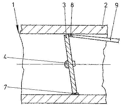
Figure 2 shows the throttle valve assembly 1 from
figure 1 in a sectional illustration along the line
II-II. In the lower half of the throttle valve assembly
1, it is illustrated that the throttle valve 3 is
sealed off with respect to the wall of the tubular
housing 2 by means of a sealing compound 7. The sealing

CA 02431931 2003-06-12
200080198
compound 7 is cured. In the event of a pivoting of the
throttle valve 3, the sealing compound 7 remains on the
tubular housing 2. The upper half shows the throttle
valve assembly 1 during the application of liquid
5 sealing compound 8 into the regions of the tubular
housing 2 and of the throttle valve 3 which are
adjacent to one another. The sealing compound 8 is
applied in drop form by means of a cannula 9 and is
transported into the gap between the tubular housing 2
and the throttle valve 3 by means of the capillary
forces. The sealing compound 8 can subsequently cure.
The sealing compound 7, 8 may be, for example, a slip
lacquer which cures after the volatilization of the
solvent and contains, for example, molybdenum sulfide
or polytetrafluoroethylene. The slip lacquer may
selectively cure or be baked at room temperature.
Figure 3 shows a further embodiment of the throttle
valve assembly 1. This differs from that from figure 1
in that the throttle valve 3 is adjustable by an
electrically drivable servomotor 10.
As figure 4 shows in a sectional illustration through
the throttle valve assembly 1 from figure 3 along the
line IV-IV during the application of the sealing
compound 7, 8, the housing 3 has, near the throttle
valve 3, two spherical segments 11 located opposite one
another. These spherical segments 11 allow a
particularly good meterability of the air throughput
through the housing 2 in the case of small opening
angles of the throttle valve 3. The introduction of the
sealing compound 7, 8 takes place as in the throttle
valve assembly 1 described in figures 1 and 2. Here,
however, after the curing of the sealing compound 7, 8,
current can be applied to the servomotor 10 and the
throttle valve 3 be pivoted.

Representative Drawing
A single figure which represents the drawing illustrating the invention.
Administrative Status

2024-08-01:As part of the Next Generation Patents (NGP) transition, the Canadian Patents Database (CPD) now contains a more detailed Event History, which replicates the Event Log of our new back-office solution.

Please note that "Inactive:" events refers to events no longer in use in our new back-office solution.

For a clearer understanding of the status of the application/patent presented on this page, the site Disclaimer , as well as the definitions for Patent , Event History , Maintenance Fee  and Payment History  should be consulted.

Event History

Description Date
Time Limit for Reversal Expired 2006-12-12
Application Not Reinstated by Deadline 2006-12-12
Deemed Abandoned - Failure to Respond to Maintenance Fee Notice 2005-12-12
Letter Sent 2004-08-26
Inactive: Correspondence - Transfer 2004-07-26
Inactive: Office letter 2004-06-08
Inactive: Single transfer 2004-05-10
Inactive: Courtesy letter - Evidence 2003-08-12
Inactive: IPRP received 2003-08-08
Inactive: Cover page published 2003-08-07
Inactive: Notice - National entry - No RFE 2003-08-04
Application Received - PCT 2003-07-16
National Entry Requirements Determined Compliant 2003-06-12
Application Published (Open to Public Inspection) 2002-06-20

Abandonment History

Abandonment Date Reason Reinstatement Date
2005-12-12

Maintenance Fee

The last payment was received on 2004-11-12

Note : If the full payment has not been received on or before the date indicated, a further fee may be required which may be one of the following

  • the reinstatement fee;
  • the late payment fee; or
  • additional fee to reverse deemed expiry.

Patent fees are adjusted on the 1st of January every year. The amounts above are the current amounts if received by December 31 of the current year.
Please refer to the CIPO Patent Fees web page to see all current fee amounts.

Fee History

Fee Type Anniversary Year Due Date Paid Date
Basic national fee - standard 2003-06-12
MF (application, 2nd anniv.) - standard 02 2003-12-12 2003-11-13
Registration of a document 2004-05-10
MF (application, 3rd anniv.) - standard 03 2004-12-13 2004-11-12
Owners on Record

Note: Records showing the ownership history in alphabetical order.

Current Owners on Record
SIEMENS AKTIENGESELLSCHAFT
Past Owners on Record
JORG FLIEGNER
PETER KOHLEN
Past Owners that do not appear in the "Owners on Record" listing will appear in other documentation within the application.
Documents

To view selected files, please enter reCAPTCHA code :


To view images, click a link in the Document Description column (Temporarily unavailable). To download the documents, select one or more checkboxes in the first column and then click the "Download Selected in PDF format (Zip Archive)" or the "Download Selected as Single PDF" button.

List of published and non-published patent-specific documents on the CPD .

If you have any difficulty accessing content, you can call the Client Service Centre at 1-866-997-1936 or send them an e-mail at CIPO Client Service Centre.

({010=All Documents, 020=As Filed, 030=As Open to Public Inspection, 040=At Issuance, 050=Examination, 060=Incoming Correspondence, 070=Miscellaneous, 080=Outgoing Correspondence, 090=Payment})


Document
Description 
Date
(yyyy-mm-dd) 
Number of pages   Size of Image (KB) 
Drawings 2003-06-11 2 51
Claims 2003-06-11 1 34
Abstract 2003-06-11 1 12
Description 2003-06-11 5 210
Representative drawing 2003-06-11 1 10
Reminder of maintenance fee due 2003-08-12 1 106
Notice of National Entry 2003-08-03 1 189
Request for evidence or missing transfer 2004-06-14 1 101
Courtesy - Certificate of registration (related document(s)) 2004-08-25 1 128
Courtesy - Certificate of registration (related document(s)) 2004-08-25 1 129
Courtesy - Abandonment Letter (Maintenance Fee) 2006-02-05 1 174
Reminder - Request for Examination 2006-08-14 1 116
PCT 2003-06-11 13 544
Correspondence 2003-08-03 1 26
PCT 2003-06-12 5 217
Correspondence 2004-06-07 1 29