Note: Descriptions are shown in the official language in which they were submitted.
CA 02432061 2003-06-16
BLOW-MOLDED CONTAINER
Technical Field
This invention relates to a peelably laminated, blow-molded container
made of synthetic resins, which is obtained by peelably laminating an outer
layer that forms an outer shell of a definite shape and an inner layer that
forms a deformable inner bag, so that the content can be discharged and used
without changing the outer appearance of this container.
Background Art
Peelably laminated containers made of synthetic resins are known and
obtained by peelably laminating an outer layer that forms an outer shell of a
finite shape and an inner layer that forms a deformable inner bag. These
blow-molded bottles are generally referred to as delaminated bottles.
An outer parison and an inner parison having no compatibility with each
other are first extruded together to give a laminated parison. This laminated
parison is then blow-molded into the peelably laminated synthetic resin
container by using a split mold for blow molding. At that time, the bottom
portion is pinched with the pinch-off of the blow mold and is pressed flat to
form a bottom seal. Since the bottom seal has basically a laminated structure
consisting of the outer layer and the inner layer, which are not compatible
with each other, there was dissatisfaction in that the outer layer is easily
cracked at the bottom.
As a conventional art to relieve this dissatisfaction, there is Japanese
Laid-Open Patent Application No. 1996-216238. In the configuration of that
invention, the bottom portion is pinched with the pinch-off of the blow mold
and is pressed flat to form the bottom seal, as described above, but the seal
is
overlaid with a pair of ribs and pressed together so that a ridge is formed
along the parting line. Some interlocks are provided at several points along
the seal as both ribs bite into each other.
In this conventional art, the bottom seal is formed into a ridge having a
certain height and width. As a result, the bottom seal has a large area of
pressed contact between the outer layer and the inner layer. The interlocks
provided at several points not only increase the area of pressed contact
further, but also increase resistance to the shearing force that is parallel
to
the plane of pressed contact, thereby making it possible to obtain a bottom
seal having a mechanical strength that is high enough to prevent the bottom
seal from cracking.
1
CA 02432061 2009-04-29
23939-71
However, in the above-described conventional art, there are cases of
cracking in the bottom seal because of the effect of time-lapsed shrinkage at
the bottom, which takes place after the containers have been blow-molded.
The problem of bottom cracking is often found especially in large-size
containers of this conventional art when they are dropped onto the floor or
when they experience a shock.
Therefore, the blow-molded containers of this kind are required to go
through complete cool-down and shrinkage within the mold. A problem
arises here because the bottom seal has large height, thickness, and cubic
volume, which need long hours of cooling and thus result in quite low
efficiency in the production of containers.
This invention has been made to solve the above-described problem. The
technical problem of this invention is to achieve strong adhesion between the
outer layers at the bottom seal without increasing the bulk of the bottom
seal.
The object of this invention is to provide a peelably laminated, blow-molded
synthetic resin container having higher strength and greater economic
efficiency at higher manufacturing efficiency than ever, without causing a
decrease in the ability of the container to sit on the bottom.
Disclosure of the Invention
Among the means of solving the above-described technical problem, the
means of carrying out a first configuration of the invention has the following
configuration. The peelably laminated, blow-molded synthetic resin
container comprises an outer layer of a synthetic resin, which forms the outer
shell- of a finite shape; an inner layer of a flexible synthetic resin, which
can
be peelably laminated with the outer layer and forms an inner bag; and a
pair of adhered zones of a vertical strip type, which is formed
axisymmetrically on the central axis of container to adhere and fix the outer
layer and the inner layer over the entire height and is located so as to avoid
the positions of air introduction ports that have been provided in the outer
layer to introduce air into the void between the outer layer and the inner
layer. In this configuration the pair_of adhered zones is provided at
positions
opposite to each other and is separated by the parting line. The lower ends of
both adhered zones are disposed at a partly or wholly end-to-end position
facing each other on the bottom seal formed when the bottom portion of the
container is pressed flat with the pinch-off of a blow mold.
In the above configuration, the container is blow-molded in a blow
mold having an ordinary pinch-off structure, i.e., a split mold for blow
molding. The bottom seal is thus the pinch-off portion formed at the bottom.
2
CA 02432061 2009-04-29
23939-71
Similarly as in ordinary blow moldings, the seal is a ridge with a low
protrusion
Since the bottom seal of this container has as fully small a cubic volume
as in ordinary blow-molded containers, the seal portion can be cooled down
quickly and sufficiently before the container is released from the mold.
Both adhered zones have their lower ends in the bottom seal. In this seal
portion where the lower ends are positioned, the outer layer is firmly adhered
and fixed to the inner layer over the total length of these lower end widths.
Here, the lower ends of both adhered zones are disposed at the end-to-
end position facing each other at the bottom seal. The outer layers and the
inner layers are fixed to each other, with the deformation caused by an
external force being restricted, over the entire range from side to side
across
both adhered zones in the center of the bottom seal.
Thus, both ends of the bottom seal and the above described fixed portion
in the center of the bottom seal serve as the junctions against the
deformation of the laminated bottom seal. Individual deformation of the
outer layer and the inner layer is inhibited also in the rest of the bottoin
seal
where there is no adhered zone. As a result, even if any force is applied on
the bottom seal, the seal is able to resist the force and is protected
securely
against cracking.
The means of carrying out a second configuration of the invention
comprises that, the lower ends of both adhered zones are dislocated
from each other to such a degree that corresponding portions of the inner
layer are not flexibly deformed.
In the second configuration, the lower ends of both adhered zones are
dislocated from each other to such a degree that corresponding portions of the
inner layers are not flexibly deformed, as describe above. Because of this
dislocation at the bottom seal, the outer layer and the inner layer are
adhered and fixed to each other by the adhered zones over the entire range
from side to side across both adhered zones in the center of the bottom seal
so
that the bottom seal can be adhered and fixed over a wide range.
The three points, i.e., both ends of the bottom seal and the above-
described adhered and fixed portion, serve as the junctions against the
deformation of the laminated bottom seal. Individual deformation of the
outer layer and the inner layer is inhibited also in the rest of the bottom
seal
other than the adhered and fixed portion. As a result, even if any force is
applied on the bottom seal, the seal is able to resist the force and is
protected
3
CA 02432061 2009-04-29
23939-71
against cracking. Since the adhered and fixed portion occupies a wide range
of the seal, this portion securely serves as a junction together with both
ends
of the seal, and effectively inhibits the individual deformation of the outer
layer and the inner layer. Thus, sufficient crack-preventing effect can be
obtained.
The lower ends of the bottom seal need not be located at a an end-to-end
position partly facing each other, but can be dislocated from each other to
such a degree that corresponding portions of the inner layers are not flexibly
deformed.
If the lower ends of both adhered zones were dislocated from each other
along the bottom seal within a range that corresponding portions of the inner
layers were not flexibly deformed, then the portion of the inner layers
between both lower ends would not be flexibly deformed. It turns out,
therefore, that one portion adhered and fixed by an adhered zone is almost
firmly connected to the other portion through this portion of inner layers.
Due to this connection, the bottom seal portions adhered and fixed with the
adhered zones keep a stable, definite posture without making these portions
deformed in vain.
If the lower ends of both adhered zones on the bottom seal were
dislocated from each other to an expanded degree, then it would be easy to
deform flexibly the portion of inner layers lying sandwiched by the adhered
zones. In that case, it would become impossible to have a firm bond that
connects this portion of inner layers with the adhered zones on both sides.
The bottom seal would also have an unstable sitting posture.
The means of carrying out a third configuration of the invention comprises
that, one lower end of an adhered zone is disposed on the
bottom seal at the wholly end-to-end position facing the other lower end of
the corresponding adhered zone.
In the third configuration, the two adhered zones are disposed at
positions opposite to each other and are separated by the parting line. The
lower ends of both adhered zones are disposed on the bottom seal at the
wholly end-to-end position facing. At this wholly end-to-end facing position,
the outer layers on both sides of the parting line and the inner layer
sandwiched by these outer layers are strongly adhered and fixed by these
adhered zones over the entire width of the lower end of each adhered zone.
As described above, the inner and outer layers form a strongly adhered
portion. Thus, the three points, i.e., both - ends of the bottom seal and the
above-described adhered portion, serve as the junctions against the
4
CA 02432061 2009-04-29
23939-71
deformation of the laminated bottom seal. Individual deformation of the outer
layer and the inner layer is inhibited also in the rest of the bottom seal
where there
is no adhered zone. As a result, even if any force is applied on the bottom
seal,
the seal is able to resist the force and is protected securely against
cracking.
The adhered zones are located roughly at axisymmetrical positions
over the entire height of the body to perform a restrictive function against
deflationary deformation of the inner layer. The adhered zones create a
symmetrical pair of unadhering portions of the inner layer (hereinafter
referred to
as unadhering inner layers). It has been made possible to proceed with the
deflationary deformation of the unadhering inner layers in a symmetrical
pattern
and to achieve smooth discharge of the contact.
The means of carrying out a fourth configuration of the invention
comprises that, the adhered zones are disposed, axisymmetrically on the
central
axis of the container, at positions dislocated from the parting line by a
central
angle of roughly 90 degrees.
In the fourth configuration, the adhered zones are located roughly at
the center of the bottom seal length. This central portion most effectively
serves
as the junction to inhibit individual deformation of the outer layers and the
inner
layers more effectively than ever and to prevent the bottom seal from cracking
to a
larger extent.
A fifth configuration of the invention comprises that, the air
introduction ports are disposed, axisymmetrically on the central axis, at two
points
in the outer layers near the parting line.
In the fifth configuration, outside air comes in through the air
introduction ports provided near the parting line. Because of these port
positions,
it has become possible to proceed with the deflationary deformation of the
unadhering inner layers in the symmetrical pattern and to achieve smooth
discharge of the content.
A sixth configuration of the invention comprises that, the air
introduction ports are provided in the neck portions of the outer layers.
5
CA 02432061 2009-04-29
23939-71
In the sixth configuration, the air introduction ports are provided at
the neck, which is covered by cap. These ports therefore do not spoil the
container appearance. When the ports are cut off in the after processing, the
ports can be drilled easily without piercing the inner bag, because the inner
layer
is considerably thick at the neck portion.
According to one aspect of the present invention, there is provided a
blow-molded container comprising: an outer layer of a synthetic resin, which
forms the outer shell of a finite shape; an inner layer of a flexible
synthetic resin,
which is laminated with the outer layer in a peelable way and forms an inner
bag;
and a pair of adhered zones of a vertical strip, which is formed
axisymmetrically
on the central axis of container to adhere and fix the outer layer and the
inner
layer over the entire height and is located so as to avoid the positions of
air intake
ports that have been provided in the outer layer and the inner layer; wherein
the
pair of said adhered zones is disposed on the sides opposite to each other
with a
parting line bordering between both sides, and at positions displaced as the
central axis of said container by about 90 degrees from the direction of the
parting
line; wherein lower ends of both adhered zones are opposed to each other at a
partly or wholly end-to-end position on bottom seal of bottom of said
container,
said bottom seal being formed when the bottom portion of the container is
pressed
flat with pinch-off section of a split mold used in blow-molding; and wherein
said
air intake ports are disposed almost, axisymmetrically on the central axis of
the
container, at two points in the outer layer on or near the parting line also
located
axisymmetrically on neck.
According to another aspect of the present invention, there is
provided the blow-molded container as described above, wherein the lower ends
of both adhered zones are dislocated from each other until an inner layer
portion
is formed to such a degree that this portion is not flexibly deformed even and
on
maximum dislocation.
According to still another aspect of the present invention, there is
provided the blow-molded container as described above, wherein the lower end
of
one adhered zone is disposed at the wholly end-to-end position facing the
counterpart of the other adhered zone.
5a
CA 02432061 2003-06-16
Brief Description of the Drawings
Fig. 1 is an overall perspective view with a partial insection showing the
container in the first embodiment of this invention.
Fig. 2 is a cross-sectional plan view of the embodiment shown in Fig. 1.
Fig. 3 is a bottom plan view of the embodiment shown in Fig. 1.
Fig. 4 is an enlarged longitudinal section of the bottom portion in the
embodiment shown in Fig. 1.
Fig. 5 is an enlarged view of the bottom seal shown in Fig. 4.
Fig. 6 is a bottom plan view of the container in the second embodiment of
this invention.
Fig. 7 is an enlarged view of the bottom seal shown in Fig. 6.
Fig. 8 is an overall perspective view with a partial insection showing the
container in the third embodiment of this invention.
Fig. 9 is a cross-sectional plan view of the embodiment shown in Fig. 8.
Fig. 10 is a bottom plan view of the embodiment shown in Fig. 8.
Fig. 11 is an enlarged longitudinal section of the bottom portion in the
embodiment shown in Fig. 8.
Fig. 12 is an enlarged view of the bottom seal of Fig. 11.
Fig. 13 is an enlarged view of the bottom seal shown in Fig. 10.
Fig. 14 is the same cross-sectional plan view as Fig. 9, which shows the
trend in the deformation of the inner layers.
Preferred Embodiments of the Invention
This invention is further described with respect to preferred
embodiments, now referring to the drawings.
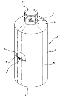
Figs. 1-5 show the first embodiment of the container 1 according to this
invention. The container 1 is a blow-molded container comprising an outer
layer 2 of a synthetic resin, such as polyethylene and polypropylene, which
forms an outer shell having a necessary ability to maintain the shape of its
own; an inner layer 3, which is molded into a flexibly deformable bag and is
made of such a resin as nylon, ethylene-vinyl-alcohol copolymer, and
polyethylene terephthalate, having no compatibility with the material of the
outer layer 2; and a pair of adhered zones 4 of a vertical strip type, which
is
disposed over the entire height of the container 1 and is made of an adhesive
resin that has full adhesiveness with both of the outer layer 2 and the inner
layer 3.
This container 1 has a circular body 6. The neck 7 is disposed standing
from the upper end of the body 6, and has screw thread notched around the
outer surface of this neck 7. The neck 7 is provided with a pair of air
6
CA 02432061 2003-06-16
introduction ports 9, which is disposed at two points on the right and left
sides, so as to introduce air into the void between the outer layer 2 and the
inner layer 3. Both adhered zones 4 are dislocated from the positions of the
air introduction ports 9 by a central angle of about 90 degrees. At the lower
end of the body 6 there is bottom 8 having an upward arched bottom wall.
As seen in Figs. 3 and 4, the bottom 8 has foot of the container 1 on the
periphery of the bottom wall. Bottom seal 10 is provided on the parting line 5
in the central part of the bottom wall, roughly crossing the bottom wall. The
seal 10 has been formed when the bottom portion was pinched off with the
pinch-off of the blow mold.
Parison is obtained by extruding together the outer cylinder to make the
outer layer 2, the inner cylinder located inside the outer cylinder to make
the
inner layer 3, and a pair of adhered zones 4 of the vertical strip type
positioned axisymmetrically on the central axis, with adhesive resine strip
being sandwiched between the outer cylinder and the inner cylinder. This
parison is then blow-molded into the container 1, by using a split mold for
blow molding.
When the container 1 is blow-molded, the parison is set in the split blow
mold at such a posture that a pair of adhered zones 4 is put in the mold
clamping direction taken from the central axis of the parison. As shown in
Fig. 3, both adhered zones 4 reach the bottom seal 10 located on the parting
line 5 of the bottom 8. Thus, as shown in Figs. 4 and 5, the adhered zones 4
strongly adhere and fix the outer layer 2 and the inner layer 3 to each other
in the central part of the pinched bottom seal 10, where both adhered zones 4
are located.
In the first embodiment shown in Fig. 3, both adhered zones 4 are
dislocated from each other to take the side-by-side positions along the bottom
seal 10. Because of this dislocation, portions of the outer layer 2 and
portions
of the inner layer 3, which are made firm against each other, have a total
width twice as long as the width of each adhered zone 4.
In the second embodiment shown in Figs. 6 and 7, both adhered zones 4
are dislocated from each other along the bottom seal 10 to such a degree that
an inner-layer portion 11 sandwiched between the lower ends of both adhered
zones 4 is not flexibly deformed. Since this inner-layer portion 11 has little
flexible deformation, those portions adhered and fixed along the bottom seal
respectively by each adhered zone 4 are almost integrally interconnected
because of this inner-layer portion 11 that is hardly deformed flexibly.
7
CA 02432061 2003-06-16
It should be noted that each air introduction port 9 is in a position
equidistant from both adhered zones 4 along the circumferential direction. In
principle, it is advantageous for the air introduction ports 9 to be located
on
the parting line 5 so that the inner layer 3 can be deflated and deformed
smoothly and efficiently.
Figs. 8-14 show the third embodiment of the container 1 according to this
invention. The container 1 is a blow-molded container comprising an outer
layer 2 of a synthetic resin, such as polyethylene and polypropylene, which
forms an outer shell having a necessary ability to maintain the shape of its
own; an inner layer 3, which is molded into a flexibly deformable bag and is
made of such a resin as nylon, ethylene-vinyl-alcohol copolymer, and
polyethylene terephthalate, having no compatibility with the material of the
outer layer 2; and a pair of adhered zones 4 of a vertical strip type, which
is
disposed over the entire height of the container 1 and is made of an adhesive
resin that has full adhesiveness with both of the outer layer 2 and the inner
layer 3.
This container 1 has a circular body 6. The neck 7 is disposed standing
from the upper end of the body 6, and has screw thread notched around the
outer surface of this neck 7. The neck 7 is provided with a pair of air
introduction ports 9, which is disposed at two points in the outer layers on
the right and left parting lines 5, so as to introduce air into the void
between
the outer layer 2 and the inner layer 3.
Both adhered zones 4 are dislocated from the parting line 5 by a central
angle of about 90 degrees.
At the lower end of the body 6 there is the bottom 8 having an upward
arched bottom wall. As seen in Figs. 10 and 11, the bottom 8 has foot of the
container 1 on the periphery of the bottom wall. Bottom seal 10 is provided
on the parting line 5 in the central part of the bottom wall, roughly crossing
the bottom wall. The bottom seal 10 has been formed when the bottom
portion was pinched off with the pinch-off of the blow mold.
Parison is obtained by extruding together the outer cylinder to make the
outer layer 2, the inner cylinder located inside the outer cylinder to make
the
inner layer 3, and a pair of adhered zones 4 of the vertical strip type
positioned axisymmetrically on the central axis, with adhesive resine strip
being sandwiched between the outer cylinder and the inner cylinder. This
parison is then blow-molded into the container 1, by using a split mold for
blow molding.
8
CA 02432061 2009-04-29
23939-71
When the container 1 is blow-molded, the parison is set in the split blow
mold at such a posture that a pair of adhered zones 4 is put in the mold
clamping direction taken from the central axis of the parison. As shown in
Fig. 10, both adhered zones 4 reach the bottom seal 10 located on the parting
line 5 of the bottom 8.
The two adhered zones 4 are separated by the parting line 5 and are
located opposite to each other. Thus, as shown in Figs. 10 and 13, the lower
ends of the adhered zones 4 are disposed at the wholly end-to-end position
facing each other in the central part of the pinched bottom seal 10
(hereinafter the portion in the end-to-end relationship between both adhered
zones is referred to as the "end-to-end facing portion 12").
Therefore, as shown in Figs. 12 and 13, the adhered zones 4 strongly
adhere and fix the outer layers 2 on both sides of the parting line 5 to the
inner layer 3 sandwiched by these outer layers 2, in this end-to-end facing
portion 12 on the pinched bottom seal 10. Since this facing portion is located
roughly at the center of the bottom seal 10, the individual deformation of the
inner layer 3 or the outer layers 2 is inhibited over the entire bottom seal
10.
Consequently, the bottom seal 10 can be prevented securely from cracking.
rn the thsrd embodiment, a pair of air introduction ports 9 is disposed at
the neck, and is located axisymmetrically on the parting line 5. The
deflationary deformation of the inner layers 3 is caused by a decrease in the
inner pressure or a decrease in the content 13, and result in the changes in
the two unadhering inner layers 14'that proceed in the symmetrical pattern.
At that time, a pair of adhered zones 4, which has been dislocated from the
parting line 5 by a central angle of about 90 degrees, performs the function
to
restrict the deformation. Thus, it is ,possible to secure the flow path and to
maintain smooth discharge operation until the content 13 is totally consumed
(See Fig. 14).
The first to third embodiments have a configuration that the two air
introduction ports 9 are located at the -neck 7 and are disposed
axisymmetrically on the parting line 5. However, this invention is not
limited to this arrangement, but the number and places of the air
introduction ports can be selected, depending on the purpose of use and the
level of difficulty in processing.
In the first to third embodiments, the container 1 has been described as
having - a two-layer structure consisting of the outer layer 2 and the inner
layer 3. However, the inner layer 3 of this invention is not limited to a
single-
layer structure, but is fully acceptable as having a laminated structure. For
instance, the two inner layers may comprise an outside synthetic resin layer
9
CA 02432061 2009-04-29
23939-71
having a peeling ability with the outer layer 2 and an inside layer of a
synthetic
resin having high resistance to the content.
Effects of the Invention
This invention having the above-described configuration has the
following effects.
The first configuration of the invention makes it possible to achieve
the cooling of the container bottom seal quickly and sufficiently. Thus, the
container production cycle can be improved to a level similar to the level
achieved
with ordinary blow-molded products.
There is no need of utilizing a special mold in which mold-cooling
efficiency has to be taken into consideration. The plant and equipment cost
can
also be reduced drastically since ordinary molds can be used.
The outer layers and the inner layers of the bottom seal can be
adhered and fixed to each other by the adhered zones in the width range larger
than the width of each adhered zone. It is possible, therefore, to prevent the
bottom securely and sufficiently from having a decreased mechanical strength
that
tends to result when the outer layer and the inner layer are formed peelably.
In the second configuration of the invention, the outer layers and the
inner layers of the bottom seal can be adhered and fixed to each other by the
adhered zones in the width range larger than the width of each adhered zone.
It is
possible, therefore, to prevent the bottom securely and sufficiently from
having a
decreased mechanical strength that tends to result when the outer layer and
the
inner layer are formed peelably.
In the third configuration of the invention, the outer layers and the
inner layers of the bottom seal can be adhered and fixed strongly to each
other by
the adhered zones. It is possible, therefore, to prevent the bottom securely
and
sufficiently from having a decreased mechanical strength that tends to result
when
the outer layer and the inner layer are formed peelably.
CA 02432061 2009-04-29
23939-71
In the fourth configuration of the invention, the adhered zones are
dislocated from the position of the parting line 5 by a central angle of
about 90 degrees, as seen on the central axis of the container. Because of
this
angle, the adhered zones can be located at the center of the bottom seal
length.
Adhesion at the center of the bottom seal enables the bottom seal to be
prevented
from cracking as much as possible.
In the fifth configuration of the invention, outside air comes in
through the air introduction ports, which are disposed near the parting line.
This
makes it possible to proceed with the deflationary deformation of the
unadhering
inner layers in the symmetrical pattern and to achieve smooth discharge of the
content.
In the sixth configuration of the invention, the air introduction ports
can be opened without giving adverse effects on the outer appearance of the
container. These ports can be drilled safely and simply in the after
processing.
11