Language selection

Search

Patent 2432254 Summary

Third-party information liability

Some of the information on this Web page has been provided by external sources. The Government of Canada is not responsible for the accuracy, reliability or currency of the information supplied by external sources. Users wishing to rely upon this information should consult directly with the source of the information. Content provided by external sources is not subject to official languages, privacy and accessibility requirements.

Claims and Abstract availability

Any discrepancies in the text and image of the Claims and Abstract are due to differing posting times. Text of the Claims and Abstract are posted:

  • At the time the application is open to public inspection;
  • At the time of issue of the patent (grant).
(12) Patent Application: (11) CA 2432254
(54) English Title: FERTILIZER KNIFE
(54) French Title: COUTEAU A ENGRAIS
Status: Deemed Abandoned and Beyond the Period of Reinstatement - Pending Response to Notice of Disregarded Communication
Bibliographic Data
(51) International Patent Classification (IPC):
  • A01C 15/00 (2006.01)
  • A01C 05/06 (2006.01)
  • A01C 23/02 (2006.01)
(72) Inventors :
  • NOWOSAD, ANTHONY W. (Canada)
(73) Owners :
  • ANTHONY W. NOWOSAD
(71) Applicants :
  • ANTHONY W. NOWOSAD (Canada)
(74) Agent: BATTISON WILLIAMS DUPUIS
(74) Associate agent:
(45) Issued:
(22) Filed Date: 2003-06-11
(41) Open to Public Inspection: 2004-12-11
Availability of licence: N/A
Dedicated to the Public: N/A
(25) Language of filing: English

Patent Cooperation Treaty (PCT): No

(30) Application Priority Data: None

Abstracts

English Abstract


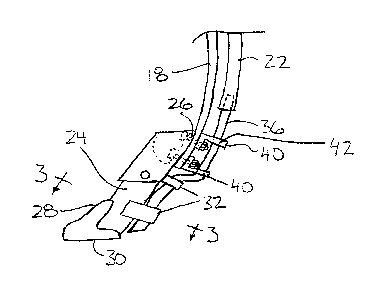
A fertilizer knife is supported on an agricultural implement shank
including a fertilizer tube extending alongside the implement shank for
delivering
anhydrous ammonia therethrough. The knife includes a dispensing tube supported
on the knife body at a trailing edge of the knife body for communication with
the
fertilizer tube to dispense fertilizer therethrough. The dispensing tube is
formed of a
material having a low heat conductivity, for example an insulating material
such as
plastic, to prevent freeze up of damp soil on the fertilizer knife when
anhydrous
ammonia is dispensed through the dispensing tube into a furrow formed in the
ground by the knife.


Claims

Note: Claims are shown in the official language in which they were submitted.


-7-
CLAIMS:
1. A fertilizer knife for use with an agricultural implement having at
least one implement shank supported for movement across the ground, said at
least
one implement shank including a fertilizer tube extending alongside the
implement
shank for delivering fertilizer therethrough, the knife comprising:
a knife body including a shank mount for mounting on said at least one
implement shank of the implement and a leading edge for projecting downward
into
the ground for creating a furrow in the ground when the implement is pulled
across
the ground; and
a dispensing tube supported on the knife body at a trailing edge of the
knife body for communication with the fertilizer tube to dispense fertilizer
therethrough;
the dispensing tube being formed of a material having a low heat
conductivity.
2. The knife according to Claim 1 wherein the dispensing tube is
formed of a material having a heat conductivity which is lower than heat
conductivity
of steel.
3. The knife according to Claim 1 wherein the dispensing tube is
formed of a plastic material.
4. The knife according to Claim 1 wherein the dispensing tube is
formed of a material which is an insulator.
5. The knife according to Claim 1 wherein there is provided a
bracket supported on the knife body which slidably receives the dispensing
tube
therethrough.
6. The knife according to Claim 1 wherein there is provided a pair
of brackets supported on the knife body at spaced positions therealong which


-8-
slidably receive the dispensing tube therethrough.
7. The knife according to Claim 1 wherein there is provided a
bracket supported by the shank mount which slidably receives the dispensing
tube
therethrough.
8. The knife according to Claim 1 wherein the dispensing tube
includes a tapered opening.
9. An agricultural implement having at least one implement shank
supported for movement across the ground, said at least one implement shank
including a fertilizer tube extending alongside the implement shank for
delivering
fertilizer therethrough and a fertilizer knife supported thereon, the knife
comprising:
a knife body including a shank mount for mounting on said at least one
implement shank and a leading edge for projecting downward into the ground for
creating a furrow in the ground when the implement is pulled across the
ground; and
a dispensing tube supported on the knife body at a trailing edge of the
knife body for communication with the fertilizer tube to dispense fertilizer
therethrough;
the dispensing tube being formed of a material having a low heat
conductivity.
10. The implement according to Claim 9 wherein the dispensing
tube is formed of a material having a heat conductivity which is lower than
heat
conductivity of steel.
11. The implement according to Claim 9 wherein the dispensing
tube is formed of a plastic material.
12. The implement according to Claim 9 wherein the dispensing
tube is formed of a material which is an insulator.
13. The implement according to Claim 9 wherein there is provided a

-9-
bracket supported on the knife body which slidably receives the dispensing
tube
therethrough.
14. The implement according to Claim 9 wherein there is provided a
bracket supported by the shank mount which slidably receives the dispensing
tube
therethrough.
15. The implement according to Claim 9 wherein the dispensing
tube includes a tapered opening.
16. A method of dispensing anhydrous ammonia into the ground
comprising:
providing an agricultural implement having at least one implement
shank supported for movement across the ground, said at least one implement
shank including a fertilizer tube extending alongside the implement shank for
delivering anhydrous ammonia therethrough;
supporting a fertilizer knife on said at least one implement shank, the
knife having a knife body with a leading edge for projecting downward into the
ground;
supporting a dispensing tube on the knife body of said fertilizer knife at
a trailing edge of the knife body for communication with the fertilizer tube;
the
dispensing tube being formed of a material having a low heat conductivity;
pulling the implement across the ground to create a furrow; and
dispensing anhydrous ammonia through the dispensing tube as the
implement is pulled across the ground.
17. The method according to Claim 16 wherein the dispensing tube
is formed of a material having a heat conductivity which is lower than a heat
conductivity of steel.
18. The method according to Claim 16 wherein the dispensing tube

-10-
is formed of a plastic material.
19. The method according to Claim 16 wherein the dispensing tube
is formed of an insulator material.
20. The method according to Claim 16 including providing a bracket
supported on the knife body which slidably receives the dispensing tube
therethrough.
21. The method according to Claim 10 including providing a bracket
supported by the shank mount which slidably receives the dispensing tube
therethrough.
22. The method according to Claim 16 wherein the dispensing tube
includes a tapered opening.

Description

Note: Descriptions are shown in the official language in which they were submitted.


CA 02432254 2003-06-11
FERTILIZER KNIFE
i=IEL~ OF THE INVENTION
The present invention relates to a fertilizer knife for an agricultural
implement for dispensing anhydrous ammonia into a furrow formed by the knife.
BACKGROUND
It is common practice to make use of anhydrous ammonia as a
fertilizer in agriculture. A common method of injecting the anhydrous ammonia
into
the ground involves pulling a furrowing element through the ground to produce
a
furrow within which the anhydrous ammonia is deposited as a liquid. The
furrowing
element typically includes a steel body which includes a metal tube extending
along
a trailing side thereof which is welded onto the body for depositing the
fertilizer
therethrough directly behind the body. In order to remain as a liquid,
anhydrous
ammonia is typically stored under very high pressures. The anhydrous ammonia
typically evaporates quickly upon exiting the tube of the furrowing element
which
causes the tube and surrounding body of the furrowing element to be rapidly
cooled
so that the surrounding moist earth readily forms a frozen clump surrounding
the
furrowing element which decreases the effectiveness of the furrowing element
at
cutting through the ground.
SUMMARY
According to one aspect of the present invention there is provided a
fertilizer knife for use with an agricultural implement having at least one
implement
shank supported for movement across the ground, said at least one implement
shank including a fertilizer tube extending alongside the implement shank for
delivering fertilizer therethrough, the knife comprising:
a knife body including a shank mount for mounting on said at least one
implement shank of the implement and a leading edge for projecting downward
into

CA 02432254 2003-06-11
-2-
the ground for creating a furrow in the ground when 'the implement is pulled
across
the ground; and
a dispensing tube supported on the knife body at a trailing edge of the
knife body for communication with the fertilizer tube to dispense fertilizer
therethrough;
the dispensing tube being formed of a material having a low heat
conductivity.
The use of a dispensing tube formed of a material having a low heat
conductivity reduces the cooling effect of the compressed liquid anhydrous
ammonia
has on the adjacent knife body to prevent the moist ground surrounding the
knife in
use from being frozen into a clump surrounding the knife.
According to a second aspect of the present invention there is provided
an agricultural implement having at least one implement shank supported for
movement across the ground, said at least one implement shank including a
fertilizer
tube extending alongside the implement shank for delivering fertilizer
therethrough
and a fertilizer knife supported thereon, the knife comprising:
a knife body including a shank mount for mounting on said at least one
implement shank and a leading edge for projecting downward into the ground for
creating a furrow in the ground when the implement is pulled across the
ground; and
a dispensing tube supported on the knife body at a trailing edge of the
knife body for communication with the fertilizer tube to dispense fertilizer
therethrough;
the dispensing tube being formed of a material having a low heat
conductivity.
According to a further aspect of the prey>ent invention there is provided
a method of dispensing anhydrous ammonia into the around comprising:

CA 02432254 2003-06-11
-3-
providing an agricultural implement having at least one implement
shank supported for movement across the ground, said at least one implement
shank including a fertilizer tube extending alongside the implement shank for
delivering anhydrous ammonia therethrough;
supporting a fertilizer knife on said at least one implement shank, the
knife having a knife body with a leading edge for projecting downward into the
ground;
supporting a dispensing tube on the knife body of said fertilizer knife at
a trailing edge of the knife body for communication with the fertilizer tube;
the
dispensing tube being formed of a material having a low heat conductivity;
pulling the implement across the ground to create a furrow; and
dispensing anhydrous ammonia through the dispensing tube as the
implement is pulled across the ground.
Preferably, the dispensing tube is formed of a material having a heat
conductivity which is lower than a heat conductivity of steel, for example an
insulating plastic material.
One or more brackets may be supportE~d on both the knife body and
the shank mount which slidably receives the dispensing tube therethrough.
The dispensing tube preferably includes a tapered opening.
BRIEF DESCRIPTION OF THE DRAVIfINGS
In the accompanying drawings, which illustrate an exemplary
embodiment of the present invention:
Figure 1 is a schematic view of an implement for injecting anhydrous
ammonia into the ground.
Figure 2 is a side elevational view of one of the knives of the
implement according to Figure 1.

CA 02432254 2003-06-11
-4_
Figure 3 is a sectional view along the line 3-3 of Figure 2.
DETAILED DESCRIPTION
Referring to the accompanying drawing;;, there is illustrated a fertilizer
knife generally indicated by reference numeral 10. Tlne knife 10 is
particularly useful
for injecting anhydrous ammonia into the ground in agricultural applications.
The knife 10 is typically supported on an implement 12 of the type
including a frame 14 supported on wheels 16 for being towed across the ground.
A
plurality of impiement shanks 18 are provided which project downwardly and
forwardly into the direction of travel from the frame 14 towards the ground. A
fertilizer tank 20 is provided which is supported on the frame 14 and is
suitably
arranged for containing anhydrous ammonia therein under high pressure.
A fluid delivery system (not shown) is provided for communication
between the tank 20 and a plurality of delivery tubes 22 associated with the
shanks
18 respectively. Each shank 18 accordingly includes one of the delivery tubes
22
extending there alongside terminating adjacent the free end of the shank.
The knife includes a knife body 24 inc~iuding a shank mount formed
adjacent a top end thereof in the form of a set of apertures 26 which receive
suitable
fasteners in the form of bolts therethrough for securement to the respective
shank
18. The knife body tapers to become narrower adjacent a bottom edge with a
sharpened narrower leading edge 28 suitably arranged for cutting through the
ground to produce a furrow when the implement is towed across the ground in
use.
A bottom free end 30 of the knife body is inclined with respect to the leading
edge so
as to lie generally parallel to the ground when the leading edge extends
upwardly
and rearwardly.
Knife brackets 32 are mounted on the trailing edge of the l~cnife body at
spaced positions therealong, each in the form of a strap in a generally U-
shaped

CA 02432254 2003-06-11
-5-
configuration which is welded to the knife body at each end to respective
sides of the
body to define an aperture 34 between the bracket and the trailing edge of the
knife
body in the mounted position of the bracket on the knife. The apertures 34 are
thus
positioned rearwardly of the knife body for slidably receiving a dispensing
tube 36
into the apertures 34 of each bracket to prevent sagging of the dispensing
tube
relative to the knife body.
The dispensing tube 36 comprises a plastic tube having an outer
diameter of 3/8 of an inch. The plastic material forming the dispensing tube
36 is an
insulator having a low heat conductivity which is much lower than the heat
conductivity of the steel forming the knife body 24. A bottom end of the
dispensing
tube 36 is cut at an incline which matches the incline of the bottom end 30 of
the
knife body relative to the longitudinal direction thereof so that the bottom
end of the
dispensing tube similarly lies parallel to the ground.
A shank bracket 40 is provided which includes a base member with
mounting apertures arranged for bolting by the fasteners securing the knife
body to
the shank 18 to permit the shank bracket 40 to be selectively separable or
mounted
on without requiring welding operations. The shank bracket also includes an
aperture 42 formed therein which slidably receives an upper portion of the
dispensing tube 36 to position the dispensing tube rearwardly of the knife
body 24
and the respective shank 18 upon which it is supported.
In use the implement is towed across the ground in the conventional
manner while anhydrous ammonia is dispensed through the delivery tubes 22 to
the
respective dispensing tubes 36 of the knives 10 on the implement. The delivery
tubes 22 on the implement conventionally have an outer diameter of '%2 of an
inch
such that an interior diameter of the delivery tubes 22 snugly receives the
respective
dispensing tubes 36 therein. The plastic material and suitable brackets for

CA 02432254 2003-06-11
_g_
securement of the plastic material of the dispensing tube onto the knife
prevents
conduction of heat being drawn away from the knife body to the anhydrous
ammonia
flowing through the dispensing tube 36 and accordingly the plastic material of
the
dispensing tube prevents considerable freeze up of moist ground onto the knife
body
~ in use.
While one embodiment of the present irwention has been described in
the foregoing, it is to be understood that other embodiments are possible
within the
scope of the invention. The invention is to be considered limited solely by
the scope
of the appended claims.

Representative Drawing
A single figure which represents the drawing illustrating the invention.
Administrative Status

2024-08-01:As part of the Next Generation Patents (NGP) transition, the Canadian Patents Database (CPD) now contains a more detailed Event History, which replicates the Event Log of our new back-office solution.

Please note that "Inactive:" events refers to events no longer in use in our new back-office solution.

For a clearer understanding of the status of the application/patent presented on this page, the site Disclaimer , as well as the definitions for Patent , Event History , Maintenance Fee  and Payment History  should be consulted.

Event History

Description Date
Application Not Reinstated by Deadline 2006-06-12
Time Limit for Reversal Expired 2006-06-12
Inactive: IPC from MCD 2006-03-12
Deemed Abandoned - Failure to Respond to Maintenance Fee Notice 2005-06-13
Application Published (Open to Public Inspection) 2004-12-11
Inactive: Cover page published 2004-12-10
Inactive: First IPC assigned 2003-08-06
Inactive: IPC assigned 2003-08-06
Application Received - Regular National 2003-07-21
Inactive: Filing certificate - No RFE (English) 2003-07-21

Abandonment History

Abandonment Date Reason Reinstatement Date
2005-06-13

Fee History

Fee Type Anniversary Year Due Date Paid Date
Application fee - small 2003-06-11
Owners on Record

Note: Records showing the ownership history in alphabetical order.

Current Owners on Record
ANTHONY W. NOWOSAD
Past Owners on Record
None
Past Owners that do not appear in the "Owners on Record" listing will appear in other documentation within the application.
Documents

To view selected files, please enter reCAPTCHA code :


To view images, click a link in the Document Description column. To download the documents, select one or more checkboxes in the first column and then click the "Download Selected in PDF format (Zip Archive)" or the "Download Selected as Single PDF" button.

List of published and non-published patent-specific documents on the CPD .

If you have any difficulty accessing content, you can call the Client Service Centre at 1-866-997-1936 or send them an e-mail at CIPO Client Service Centre.


Document
Description 
Date
(yyyy-mm-dd) 
Number of pages   Size of Image (KB) 
Description 2003-06-10 6 314
Abstract 2003-06-10 1 23
Claims 2003-06-10 4 164
Drawings 2003-06-10 1 16
Representative drawing 2003-10-02 1 7
Filing Certificate (English) 2003-07-20 1 158
Reminder of maintenance fee due 2005-02-13 1 109
Courtesy - Abandonment Letter (Maintenance Fee) 2005-08-07 1 175