Note: Descriptions are shown in the official language in which they were submitted.
CA 02432293 2003-06-19
WO 03/009796 PCT/USO1/23234
MEDICAL BED SYSTEM WITH INTERCHANGEABLE MODULES FOR
MATTRESS SYSTEMS AND RELATED METHODS
FIELD OF THE INVENTION
The present invention relates to modular therapeutic patient support
systems. More particularly, this invention relates to therapeutic beds,
therapeutic mattresses adaptable to varying types of surfaces; and
modifications and controls which enable therapeutic bed frames to
sequentially and independently accept various therapeutic supports
depending upon a patient's particular therapeutic needs.
BACKGROUND
The field of therapeutic patient supports has been well developed
since at least the 1960s and 70s. While various kinds of therapeutic patient
supports exist, inflatable therapeutic patient supports have, over time,
become increasingly popular. These supports are more complex than a
conventional medical therapeutic mattress as they require additional control
systems to regulate the inflation of all or part of the mattress. Such early
therapeutic beds were very expensive, requiring complicated control systems
to be integrated within the dedicated bed frame supporting the inflatable
surface. These systems, which still exist today, still require dedicated bed
frames, and, to the extent practical, are restricted to patients requiring a
high level of patient care, beyond that provided by a static, pressure
relieving mattress.
Through the years, therapeutic patient support system purchasers,
mostly health care providers, began demanding static pressure relieving
mattress systems that were adapted for use with conventional bed frames,
which did not require the uses of a dedicated frame, as do more complex
1
CA 02432293 2003-06-19
WO 03/009796 PCT/USO1/23234
systems referred to above. These conventional bed frames, as is well known
in the art, generally have front or rear portions, and usually both, that may
be raised, or lowered, as desired, commonly by means of patient remote
controllable electric motors. As a consequence, the baseboards of such
beds are articulable, and are divided into a plurality of independently
moveable planar sections, most usually a head section, a body section, and
a foot section. This allowed, and allows, a health care provider, such as a
hospital, to use different therapeutic mattress system with the same bed
frame. This also allowed bed frames to be moved among various services as
patient census may dictate.
A typical example is the First Step Select~ mattress system available
from Applicant. This system provides an inflatable, low-air-loss patient
support with multiple zones of pressure control, together with heater control
and other features. A compact control unit that was adapted to be hung on
the footboard of a standard hospital bed frame regulates all of these
features. Such a system enables a conventional hospital bed to be equipped
with a standard medical mattress for most patients, but when required a
low air loss mattress could be installed instead, with the mattress control
system mounted (or hung) upon the footboard of the bed. Other such
mattress systems were also offered under the "MRS" (mattress replacement
system) designation to replace the entire mattress.
Significant problems arise from placing controls on the bed footboard.
This footboard is valuable space and typically is the preferred location for
putting patient clipboards, and other frequently used devices. This allows
them to be placed both close to the patient, and to be readily accessible to
medical caregivers. Also, a patient care room is often cluttered. Having a
protrusion beyond the preexisting footprint of the bed could lead to the
controls, and the bed attached thereto being inadvertently jostled. This
could lead to patient discomfort, or worse.
2
CA 02432293 2003-06-19
WO 03/009796 PCT/USO1/23234
As is well known in the art, conventional medical bed frames,
generally have front or rear portions that may be raised, or lowered, as
desired, commonly by means of patient controllable electric motors. As a
consequence, the baseboards, which support the mattress of such beds are
articulable, and are divided into a plurality of independently moveable
planar sections, including at least a head section, a body section, and a foot
section. Further, the space beneath the baseboards is not empty.
Conventional medical bed frames typically use electrically driven
mechanisms, such as jackscrews or worm gears for adjusting the elevation
and inclination of the various portions of the bed. Most commonly this
mechanism is centrally disposed on the underneath of the baseboards, and
occupies some portion of the centerline portion of the space there defined,
much like the well known transmission hump long found in rear wheel drive
automobiles equipped with automatic transmissions. Fortunately, likely for
mechanical reasons, this configuration is reasonably standard.
More recently, various other bed frames have been commercialized
with a modularized approach, wherein the bed frame is adapted for a variety
of mattress systems. The Total Care system, commercialized by Hill-Rom,
Inc., of Batesville, Indiana, is a typical example. That system is
commercialized with a bed frame that is customized during manufacture to
receive a variety of different surfaces. Particulars of this system may be
better understood frc:m the following U. S. Patents where are believed to be
related to the Total Care System US include 5,630,238 issued May 20,
1997, Weismiller et al, incorporated herein by this reference thereto.
To date, however there has been no patient support system which
provides an inflatable pressure relieving patient support system which
coacts with a conventional medical bed frame to provide a low air loss
inflatable mattress which is contained within such a bed frame, which also
has its control and power modules also located within the footprint of such
a bed. It is towards meeting this need that the present invention is directed.
3
CA 02432293 2003-06-19
WO 03/009796 PCT/USO1/23234
BRIEF DESCRIPTION OF THE INVENTION
The present invention embodies an inflatable patient support, and a
control and power system required for its operation, which fit within,
beneath, and upon a conventional hospital bed frame, after the bed frame
has been internally modified. The system operatively interacts with a bed
frame, and comprises a modular control assembly, an inflatable mattress
and various operative connections there between. In the preferred
embodiment this is a conventional bed frame that, although modified to
receive the modular control assembly may also support a wide variety of
other mattresses as are typically employed within the medical environment.
Then, when a pressure-relieving surface is required, the foot end
baseboard of the frame can be removed and replaced with the modular
control assembly and mattress can be utilized with the system without the
necessity of utilizing a blower control assembly that hangs on the footboard
or is placed on the floor in the patient room.
An object of the present invention is to provide a means whereby a low
air loss inflatable pressure-relieving mattress, and the power / control
module thereof, may be installed upon and within the footprint of a
conventional hospital bed.
Another object of the present invention is to provide a means whereby
a low air loss inflatable pressure-relieving mattress, and the power / control
module thereof, may be installed upon and within the footprint of a
conventional hospital bed, wherein the controls are accessible to a caregiver
of the user of the mattress.
A further object of the present invention is to provide a means
whereby a low air loss inflatable pressure-relieving mattress, and the power
/ control module thereof, may be installed upon and within the footprint of
a conventional hospital bed, by locating this module within space otherwise .
wasted in the cavity beneath the foot end baseboard of a conventional
hospital bed.
4
CA 02432293 2003-06-19
WO 03/009796 PCT/USO1/23234
These and still further objects and advantages of the invention will be
readily apparent to those skilled in the art from the following description
taken in conjunction with the accompanying drawings. The drawings
constitute part of this specification and include exemplary embodiments of
the present invention and illustrate various objects and features thereof.
BRIEF DESCRIPTION OF THE DRAWINGS
FIG 1 is a partial isometric perspective view of a therapeutic patient support
system embodying the various aspects of the present invention.
FIG 2 is a top perspective view of the modular control assembly.
FIG 3 is a partial exploded view of the modular control assembly of FIG 2.
FIG 4 is a front view of the control panel of the modular control assembly
FIG 5 shows the control panel of an alternative embodiment of the present
invention.
DETAILED DESCRIPTION OF THE PREFERRED EMBODIMENTS
The present invention may be embodied in a wide variety of
therapeutic patient support systems. Fig's 1-4 depict a first preferred
embodiment of the present invention represented within therapeutic patient
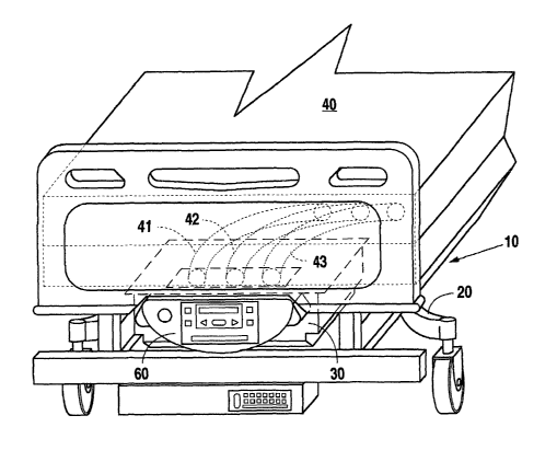
support system 10. As most clearly illustrated in FIG 1, the system 10
operatively interacts with a bed frame 20, and comprises a modular control
assembly 30, a mattress 40, and various operative connections there
between.
In the preferred embodiment, frame 20 is a conventional bed frame
that, although modified to receive modular control assembly 30, may also
support a wide variety of other mattresses as are typically employed within
the medical environment. Then, when a pressure-relieving surface is
required, the foot end baseboard of frame 20 can be removed and replaced
with the modular control assembly 30, and mattress 40 can be utilized with
s
CA 02432293 2003-06-19
WO 03/009796 PCT/USO1/23234
the system without the necessity of utilizing a blower control assembly that
hangs on the footboard or is placed on the floor in the room.
More particularly, frame 20 of the presently most preferred
embodiment is a Hill-Rom Model 834A or 835 frame that has been adapted
to allow space for receiving the modular control assembly 30. Such
conventional bed frames are available with baseboards including a foot
section baseboard of the same shape as baseboard 31. In contrast to a
spring surface, such baseboards are suited for use in the medical industry
when therapeutic mattresses, are installed upon bed frame 20.
With reference to Figures 2 and 3, modular control assembly 30
comprises baseboard 31, blower control assembly 32 attached thereto, and
air hose outlets 33-35, which are provided within recess 36 defined within
baseboard 31. In the usual operating configuration, hose 41 is operatively
connected to outlet 33, hose 42 is operatively connected to outlet 34, and
hose 43 is operatively connected to outlet 35. The precise function and
uses of hoses 41, 42, 42, when connected to outlets 33, 34, 35, is described
more fully below. w
Figure 2 shows the molded, plastic shroud 200that covers the
individual components of blower control assembly 32. Shroud 200 is
described in greater detail, below.
Figure 3 depicts in exploded view the devices and components of an
exemplary embodiment of blower control assembly 32. Power switch
assembly 151 is mounted to bracket 150 and is equipped to receive a
conventional power cord. Assembly 151 has a rocker style toggle switch to
interrupt or allow flow of electrical power to the electronic control board
152, that in turn processes signals and directs electrical power to blower
motor 153 and to pinch valves 162, 163, and 164, which are mounted on
hose valve mounting bracket 165.
Foam block 154 fits snugly over blower motor 153 to reduce noise
and vibration from blower motor 153. Blower motor 153 is seated in a
Styrofoam nest, which sets snugly into a shallow, rectangular metal frame
6
CA 02432293 2003-06-19
WO 03/009796 PCT/USO1/23234
176. Metal frame 176 is affixed to baseboard 31 by machine screws. No
bolts, or strap holds the blower motor to baseboard 31. This is so to
prevent and/or reduce transmitting mechanically induced vibration from
blower motor 153 to bed frame 20. Blower motor 153 is held in place by
virtue of mechanical pressure exerted by the shroud 200 pressing upon
foam block 154.
Electric wires and spaghetti air tubes are "dressed" around various
components by means of commercially available management appliances,
such as open spiral cable wrap tubing and cable tie down clamps, as are
well known to those skilled in the art.
The air output chamber of blower motor 153 is mechanically linked
to air/ heater manifold 155. Temperature sensor 156 is affixed to and
imbedded into manifold 155. Temperature sensor 156 is also electrically
linked to control board 152, and provides blower air temperature signals to
control board 152 for processing along with other signals.
Further referring to Figure 3, three air hoses 158, 159, and 160
proceed from air/heater manifold 155 and continue through, in
substantially parallel configuration, valve assembly 161. Three pinch valve
controllers 162, 163, and 164 are mounted onto valve assembly 161,
directly above each air hose 158, 159, and 160, respectively.
As shown in Figure 4, the preferred embodiment of the present
invention is adapted to provide customers with one of the popular First
Step Select mattress systems available from Applicant. Figure 4 depicts a
control panel 60 for such a system. Control panel 60 includes a power
button 61 and a First Step Select membrane panel 62 as is presently
commercialized with the First Step Select blower unit. The functions of the
First Step Select membrane panel and its related components are virtually
identical to the function of like components and controls in the First Step
Select mattress systems presently on the market. Hence, once modular
control assembly 30 has been installed within therapeutic patient support
system 10, and once mattress 40 and its related air hoses 41-43 have been
7
CA 02432293 2003-06-19
WO 03/009796 PCT/USO1/23234
connected to outlets 33-35, respectively, system 10 is ready to provide
patient pressure relief and other therapeutic features for patients.
In an alternative embodiment, TheraPulse Light control panel 60' may
replace the deformed elongated oval FirsStep Select control panel 60. The
Theral'ulseLight control panel and basic air handling components used
therewith, are the same as are used in the commercialized Theral?ulseLight
unit sold by assignee. The face 201' of this control panel 60' is an elongated
irregular hexagon. Either of such shapes, or any other desirable shaped
control panel 60 could be used.
Figure 5 provides frontal view of the TheraPulse Light control panel
60'. This control interface has the power switch integral with the control
panel membrane.
Referring to Figure 6, baseboard 31 is a rigid, phenolic, flat,
rectangular board measuring approximately 36.5 inches wide, 26 inches
front to back, and 0.25 inches thick; two of its adjacent corners are
rounded to a radius of approximately 5 inches. Baseboard 31 is of such
material so as to be machine bolt thread tapable to accept machine bolts
without need for nuts. Holes for handholds are cut into baseboard 31 at
opposite sides; the presently preferred dimensions for such handholds are
approximately 1.75 inches wide by 5 inches long. Further reference to
Figure 6 shows schematically the components inside first preferred
embodim~:nt of blower control assembly 32. Components that constitute
blower control assembly 32 are affixed to baseboard 31.
Control panel 60 protrudes from the foot end of the bed frame 20 as
depicted in Figure 1, but does not extend beyond the footprint established
by frame 20. Alternate embodiments for equipping conventional bed frames
can be achieved with baseboard options when manufacture supplied
baseboards of the same shape, or substantially the same shape as
baseboard 31, shown in Figure 2, are provided by the bed frame
manufacturer.
s
CA 02432293 2003-06-19
WO 03/009796 PCT/USO1/23234
Such electronic, electro-mechanical, and mechanical devices
schematically depicted in Figure 6 are substantially similar to those found
in the First Step Select mattress system available from assignee. The
individual devices and components are well known to those skilled in the
art and therefore do not require detailed description herein. electronic,
electro-mechanical, and mechanical devices herein are operatively
connected to baseboard 31, either directly, or to a bracket such as bracket
176 that is preferrably fabricated from a corosion resistant easily
machineable metal such as aluminum. Bracket 176 is in turn fastened to
baseboard 31 presenting a somewhat "flat" configuration upon baseboard
31. Mounting of individual components to baseboard 31 may be
accomplished by use of standard machine bolt screws into holes threaded
into baseboard 31, as are well known in the art, or in any other
conventional manner known to the art that does not have an adverse
impact on the operation of the present invention.
No bolts or other fastening devices should extend out the opposite
side of baseboard 31 more than 1 / 64 to 1 / 32 of an inch; that being the
side of baseboard 31 upon which mattress 40 rests. Although there is
nothing unique about the method of mounting the individual components
to baseboard 31, any alternative mounting method is contemplated by the
teachings of this invention. For example, all of the components could be
mounted to a chassis, which could in turn be mounted to baseboard 31.
A molded, high impact plastic, contoured shroud 201, shown
partially in Figure 2, preferably covers all of the devices and components of
blower control assembly 32 when affixed to baseboard 31, and is held in
place to it by machine screws. Shroud 201 has openings for access to
power switch assembly 151, features a filtered air inlet for blower motor
153, and a cut-away area to receive and accommodate a control panel 60.
Of particular importance to the shape of the shroud is a 5 inch wide by 4
inch deep channel 205 that runs the length of shroud 201. Channel 205
(partially visible in Fig. 2) is of sufficient depth, width, and length to
9
CA 02432293 2003-06-19
WO 03/009796 PCT/USO1/23234
accommodate mechanical features of bed frame 20, especially the centrally
disposed jack-screws, also known as worm gears, of bed 20 that articulate
the foot baseboard portion of bed 20.
Air/heater manifold 155 and valve assembly 161 are mounted to
metal bracket 177, which is in turn, mounted to baseboard 31. Metal
bracket 177 is longer than it is wide, is bent at several substantially right
angles to provide plateaus of various heights from baseboard 31 to
accommodate mounting of valve assembly 161 and allow hoses 158, 159,
and 160 to pass from air/heater manifold 155 beneath pinch valves 162,
163, and 164, and continue on to hose port block 166.
Pinch valve controllers 162, 163, and 164 regulate the volume of air
that flows through air hoses 158, 159, and 160. Pinch valve assemblies
162, 163, and 164 respond to electrical signals produced by electronic
control board 152.
Air hoses 158, 159, and 160 proceed on from through valve assembly
161 to three ports, respectively, on one face of hose port block 166. On the
obverse side of hose port block 166 are three air hose outlets 33, 34, and
35, depicted in Figure 2 and Figure 3. From these outlets 33, 34, and 35,
air hoses proceed to mattress 40.
On an adjacent face of hose port blocl~ 166 are three, air pressure
sensing ports 171, 172, and 173. Proceeding from the pressure sensing
ports 171, 172, and 173 are three air pressure sensor, spaghetti hoses 168,
169, and 170, that connect to three pressure transducers on and integral
to electronic control board 152. This air pressure sensing configuration
provides feedback signals to electronic control board 152. A fourth pressure
transducer integral to electronic control board 152 is linked by yet another
air spaghetti hose to air/heater manifold 155 to provide air temperature
feedback to electronic control board 152.
These three pressure ports 171, 172, and 173 provide pneumatic
feedback to electronic control board 152 for the feet, body and head aspects
of air being delivered to those respective zones of air mattress 40. The
to
CA 02432293 2003-06-19
WO 03/009796 PCT/USO1/23234
proximate end of a flat ribbon electric cable attaches to electronic control
board 152 and the distal end thereof attaches to a First Step Select
membrane panel 62 of the preferred embodiment as shown in Figures 1-3.
An alternative control panel is the TheraPulse Light depicted in Figure 5.
In sum, Figures 1 - 6 show a basic bed frame 20 adapted to
accommodate modular control assembly 30, and figure by figure zoom in to
reveal greater detail of blower control assembly 32 and alternate control
panels 60, 60'.
Many references have been made in this detailed description to
particular commercial embodiments, such as the First Step Select, the
TheraPulse Light and others. It should be recognized by those of ordinary
skill in the art, however, that such reference is made because that is
Applicant's present perspective - to utilize the present invention together
with such products. It is readily contemplated, however, that the present
invention will be utilized with many other mattress systems as are available
from Applicant's current and future competitors.
11