Language selection

Search

Patent 2432306 Summary

Third-party information liability

Some of the information on this Web page has been provided by external sources. The Government of Canada is not responsible for the accuracy, reliability or currency of the information supplied by external sources. Users wishing to rely upon this information should consult directly with the source of the information. Content provided by external sources is not subject to official languages, privacy and accessibility requirements.

Claims and Abstract availability

Any discrepancies in the text and image of the Claims and Abstract are due to differing posting times. Text of the Claims and Abstract are posted:

  • At the time the application is open to public inspection;
  • At the time of issue of the patent (grant).
(12) Patent: (11) CA 2432306
(54) English Title: HELICOPTER ROTOR HUB, AND ROTOR FEATURING SUCH A HUB
(54) French Title: MOYEU DE ROTOR D'HELICOPTERE, ET ROTOR ASSOCIE
Status: Deemed expired
Bibliographic Data
(51) International Patent Classification (IPC):
  • B64C 27/48 (2006.01)
  • B64C 27/32 (2006.01)
  • B64C 27/35 (2006.01)
(72) Inventors :
  • PANCOTTI, SANTINO (Italy)
(73) Owners :
  • AGUSTA S.P.A. (Italy)
(71) Applicants :
  • AGUSTA S.P.A. (Italy)
(74) Agent: RIDOUT & MAYBEE LLP
(74) Associate agent:
(45) Issued: 2010-09-28
(22) Filed Date: 2003-06-13
(41) Open to Public Inspection: 2003-12-14
Examination requested: 2008-05-27
Availability of licence: N/A
(25) Language of filing: English

Patent Cooperation Treaty (PCT): No

(30) Application Priority Data:
Application No. Country/Territory Date
TO2002A 000509 Italy 2002-06-14

Abstracts

English Abstract

There is described a hub for a helicopter rotor, having a main body, and a number of connecting members projecting from the main body and for the connection of respective blades; the main body and the connecting members being defined by separate components connectable to one another by releasable fastening means.


French Abstract

Moyeu de rotor d'hélicoptère comprenant un corps principal et des éléments de couplage saillant du corps principal pour le couplage des pales; le corps principal et les éléments de couplage sont constitués d'éléments séparés pouvant se raccorder les uns aux autres par des éléments de fixation temporaire.

Claims

Note: Claims are shown in the official language in which they were submitted.


6

CLAIMS


1) A hub for a helicopter rotor, comprising a main body, and a
number of connecting members projecting radially from said main
body and defining, with said main body, respective closed-profile
seats for receiving respective blades; each connecting member
being defined by a component separated from said main body and
being connectable to said main body by releasable fastening means.

2) A hub as claimed in Claim 1, wherein each connecting member
is substantially C-shaped, and comprises two facing arms joined by
a transverse connecting portion and fixed at their free ends to
said main body by said releasable fastening means.

3) A hub as claimed in claim 1 or 2 wherein said main body is
substantially cylindrical.

4) A hub as claimed in Claim 3, wherein said main body defines
integrally, at opposite axial ends, respective radial flanges for
supporting and fastening respective said free ends of each
connecting member.

5) A hub as claimed in Claim 4, wherein said releasable
fastening means comprise a number of bolts having axes parallel to
the axis of said main body, and connecting said free ends of each
connecting member to said flanges.

6) A helicopter rotor comprising a hub, and a plurality of
blades extending radially from said hub, said hub being formed as
claimed in any one of claims 1 to 5, and each blade comprising a
connecting portion for connection to said hub and defining a
through opening through which said connecting portion of the
relative connecting member extends.


7

7) A rotor as claimed in Claim 6, including bearing means

interposed between said connecting portion of each blade and said
connecting portion of the relative connecting member.

Description

Note: Descriptions are shown in the official language in which they were submitted.


CA 02432306 2003-06-13
1

HELICOPTER ROTOR HUB, AND ROTOR FEATURING SUCH A HUB
The present invention relates to a helicopter rotor
hub, in particular for a tail rotor, to which the

following description refers purely by way of example.

As is known, a helicopter tail rotor substantially
comprises a hub connected angularly to the rotor drive
shaft, and a number of blades fixed to and projecting
radially from the hub.

The hub typically comprises a substantially
cylindrical central body, in turn comprising an axial
through hole for the drive shaft, and a number of integral
outer radial supporting arms, each defining a fastening
seat for connection of a respective blade.

Each blade is normally fitted on one end with a
fastening member for connection to a relative arm on the
hub. More specifically, the fastening member is typically
C-shaped, and comprises opposite parallel end portions
connected releasably to one end of the relative blade to

define a closed through seat with the blade, and a
connecting portion for connecting the end. portions and
fitted through the fastening seat of the relative arm on
the hub.

Known hubs of the above type are extremely bulky and
heavy, and therefore difficult to manage when fitting and
removing the rotor to and from the helicopter. This is
mainly due to the supporting arms, which greatly increase


CA 02432306 2009-12-07
2

the radial size of the hub.

The present invention provides a helicopter rotor hub
designed to eliminate, in a straightforward, low-cost manner,
the aforementioned drawback typically associated with known
hubs.

According to the present invention, there is provided a
hub for a helicopter rotor, comprising a main body, and a
plurality of connecting members projecting radially from the
main body and defining, with the main body, respective closed

profile seats for receiving respective blades. Each
connecting member is defi,ned by a component separated from the
main body and connectable to the main body by releasable
fastening means.

A preferred, non-limiting embodiment of the present
invention will be described by way of example with reference
to the accompanying drawings, in which:

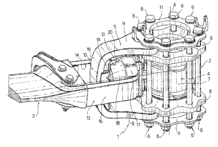
Figure 1 shows a view in perspective, with parts removed
for clarity, of a helicopter rotor hub in accordance with the
present invention;

Figure 2 shows a cross section of the Figure 1 hub.

With reference to the accompanying drawings, number 1
indicates as a whole a rotor - in the example shown, a tail
rotor - for a helicopter (not shown), and which substantially
comprises a hub 2, of axis A, connected angularly to a drive

shaft 15 (shown partly in Figure 2) of rotor 1; and a number
of blades 3 (only one of which is shown partly) fixed radially
to and projecting from hub 2 in the manner described below and
which constitutes the


CA 02432306 2003-06-13
3

object of the present invention.

More specifically, hub 2 comprises a hollow,
substantially cylindrical, central body 4, of axis A, for
receiving and rotated by drive shaft 15 in known manner

not described; and a number of connecting members 5
projecting radially from body 4 and for the connection of
respective blades 3.

An important characteristic of the present invention
is that body 4 and connecting members 5 are defined by
separate components connected to one another releasably by
a number of bolts 6.

More specifically, body 4 comprises a cylindrical
main portion 7 of axis A; and opposite annular end flanges
8 projecting radially from main portion 7-

Each connecting member 5 is substantially C-shaped,
and is defined by two facing arms 9 joined by a transverse
connecting portion 10 and fixed at their free ends to body
4 by means of bolts 6.

More specifically, the free ends of arms 9 of each
connecting member 5 rest on respective flanges 8 of body
4, and are gripped between flanges 8 and respective
annular end plates 11. Flanges 8 are fastened to annular
plates 11 by means of bolts 6, which have axes parallel to
axis A and are equally spaced angularly about axis A and
outwards of the main portion of body 4.

Each connecting member 5 defines, with the portion of
body 4 facing it, a closed seat 12 for receiving relative


CA 02432306 2003-06-13
4

blade 3.

As shown in the accompanying drawings, each blade
comprises, at one end, a portion 13 for connection to hub
2 and defining a closed through opening 14 through which

connecting portion 10 of relative connecting member 5
extends.

More specifically, portion 13 of each blade 3 is
substantially C-shaped with opposite ends originating from
the body of blade 3; and the C's formed by each connecting

member 5 and by portion 13 of each blade 3 lie in planes
perpendicular to each other.

Each portion 13 is defined by two substantially
parallel branches 16 forming extensions of relative blade
3 and joined by a transverse connecting portion 17.

Each connecting member 5 is connected to portion 13
of each blade 3 by means of a bearing 18 allowing blade 3
to move in all possible planes.

More specifically, connecting portion 10 of each
connecting member 5 and connecting portion 17 of portion
13 of relative blade 3 respectively comprise a convex

projection 19 and a concave recess 20, between which
bearing 18 is housed.

The advantages of rotor 1 and hub 2 according to the
present invention will be clear from the foregoing
description.

In particular, hub 2 according to the invention is
easier to manage when being fitted tc the helicopter, by


CA 02432306 2003-06-13

being defined by a number of separate, relatively small,
lightweight parts (main body 4 and connecting members 5).
Clearly, changes may be made to rotor 1 and hub 2 as

described and illustrated herein without, however,
5 departing from the scope of the accompanying Claims.

Representative Drawing
A single figure which represents the drawing illustrating the invention.
Administrative Status

For a clearer understanding of the status of the application/patent presented on this page, the site Disclaimer , as well as the definitions for Patent , Administrative Status , Maintenance Fee  and Payment History  should be consulted.

Administrative Status

Title Date
Forecasted Issue Date 2010-09-28
(22) Filed 2003-06-13
(41) Open to Public Inspection 2003-12-14
Examination Requested 2008-05-27
(45) Issued 2010-09-28
Deemed Expired 2017-06-13

Abandonment History

There is no abandonment history.

Payment History

Fee Type Anniversary Year Due Date Amount Paid Paid Date
Application Fee $300.00 2003-06-13
Registration of a document - section 124 $100.00 2003-11-21
Maintenance Fee - Application - New Act 2 2005-06-13 $100.00 2005-04-27
Maintenance Fee - Application - New Act 3 2006-06-13 $100.00 2006-04-21
Maintenance Fee - Application - New Act 4 2007-06-13 $100.00 2007-04-30
Maintenance Fee - Application - New Act 5 2008-06-13 $200.00 2008-05-06
Request for Examination $800.00 2008-05-27
Maintenance Fee - Application - New Act 6 2009-06-15 $200.00 2009-05-26
Maintenance Fee - Application - New Act 7 2010-06-14 $200.00 2010-05-12
Final Fee $300.00 2010-07-09
Maintenance Fee - Patent - New Act 8 2011-06-13 $200.00 2011-05-09
Maintenance Fee - Patent - New Act 9 2012-06-13 $200.00 2012-05-14
Maintenance Fee - Patent - New Act 10 2013-06-13 $250.00 2013-05-14
Maintenance Fee - Patent - New Act 11 2014-06-13 $250.00 2014-05-15
Maintenance Fee - Patent - New Act 12 2015-06-15 $250.00 2015-06-09
Owners on Record

Note: Records showing the ownership history in alphabetical order.

Current Owners on Record
AGUSTA S.P.A.
Past Owners on Record
PANCOTTI, SANTINO
Past Owners that do not appear in the "Owners on Record" listing will appear in other documentation within the application.
Documents

To view selected files, please enter reCAPTCHA code :


To view images, click a link in the Document Description column. To download the documents, select one or more checkboxes in the first column and then click the "Download Selected in PDF format (Zip Archive)" or the "Download Selected as Single PDF" button.

List of published and non-published patent-specific documents on the CPD .

If you have any difficulty accessing content, you can call the Client Service Centre at 1-866-997-1936 or send them an e-mail at CIPO Client Service Centre.


Document
Description 
Date
(yyyy-mm-dd) 
Number of pages   Size of Image (KB) 
Abstract 2003-06-13 1 12
Description 2003-06-13 5 160
Claims 2003-06-13 2 61
Drawings 2003-06-13 2 91
Representative Drawing 2003-08-26 1 34
Cover Page 2003-11-18 1 57
Description 2009-12-07 5 157
Claims 2009-12-07 2 45
Cover Page 2010-09-01 1 61
Fees 2008-05-06 1 38
Correspondence 2003-07-22 1 24
Assignment 2003-06-13 3 84
Prosecution-Amendment 2003-08-06 2 88
Assignment 2003-11-21 3 93
Prosecution-Amendment 2008-05-27 1 32
Fees 2005-04-27 1 28
Fees 2006-04-21 1 26
Fees 2007-04-30 1 29
Fees 2009-05-26 1 35
Prosecution-Amendment 2009-10-07 2 67
Prosecution-Amendment 2009-12-07 6 192
Fees 2010-05-12 1 35
Correspondence 2010-07-09 1 34
Fees 2011-05-09 1 202