Note: Descriptions are shown in the official language in which they were submitted.
CA 02432516 2007-04-03
Device for Distracting or Compressing Bones or Bone Fragments
This invention reiates to a system for applying axial forces on at least two
bone fragments or
vertebral bodies with which the system can be connected, encompassing
A) a first connecting element (1), with a longitudinal axis (27), that can be
connected to a
bone fragment or a vertebral body, and
B) a second longitudinal connecting element (2), with a longitudinal axis
(17), that can be
connected to another bone fragment or vertebra, with the longitudinal axes
(17, 27) defining a
plane (18) while the second connecting element (2) is movable relative to the
first connecting
element (1) in a manner whereby the longitudinal axis (17) travels within the
plane (18);
characterized in that the system
C) also includes, coaxially with the longitudinal axis (27), a longitudinal
support (4) with a
longitudinal axis (5), a back end (7) and a front end (6) that can be
connected to the first
connecting element (1), with the longitudinal axis (5) extending parallel to
the plane (18);
D) includes a tubular sleeve (8) that extends coaxially with the longitudinal
axis (5) and is
provided with a coaxial end-to-end bore (11) within which the longitudinal
support (4), featuring a
forward end piece (9) that faces the first connecting element (1) as well as a
rearward end piece
(10), is movable parallel to the longitudinal axis (5);
E) comprises a first lever (12) that connects the forward end piece (9) to the
second
connecting element (2), that has a longitudinal axis (16) that extends
essentially parallel to the
plane (18) and which is attached to the end piece (9) in rotatable fashion,
whereby the
longitudinal axis (16) can be swiveled in a direction essentially parallel to
the plane (18); also
F) includes at least one second lever (13) whose longitudinal axis extends
essentially
parallel to the plane (18) and which is pivotably attached to the first
connecting element (1) and
to the second connecting element (2) in a manner whereby the longitudinal axis
(15) can be
swiveled essentially parallel to the plane (18), so that
G) a relative movement between the forward end piece (9) and the first
connecting element
(1) parallel to the longitudinal axis (5) produces a relative movement between
the first and the
second connecting element (1, 2) along a line (20) that extends parallel to
the plane (18) and
essentially in a transverse direction relative to the longitudinal axis (5).--
.
For example, if a vertebra is diseased or damaged, it may have to be removed
from the spine. In
place of that vertebra a spacer implant is grafted in. Implants usually
encompass mutually
shiftable components as well as two special end plates serving to anchor the
impiant in the
adjoining healthy vertebrae. In many other cases an internal fixation system
is attached in a
manner whereby it connects two vertebrae, with the fixation system bridging
one or even several
defective vertebrae. In the case of these predominantly plate-shaped implants
the end-plate
sections are fastened to the vertebrae by means of bone screws. The connecting
elements
between the end-plate sections are of a telescoping design, allowing the
vertebrae next to the
defective vertebral bodies to move parallel to the spinal axis in expansile or
contractile fashion.
Yet other spinal fixation systems consist of rod-shaped longitudinal supports
that can be
attached to pedicle screws via connecting elements. These connecting elements
are so
designed that they can slide along the longitudinal supports in an axial
direction, again permitting
expansile and contractile movement between the vertebrae. These provisions
often require a
spreading or compression of vertebrae or implant segments by means of
appropriate
instruments.
A system for spreading vertebrae has been described in US 4,898,161 by
GRUNDEI. This
earlier spreading system features a pincer-like design of two levers axially
extending into two
jaws that can be equipped with pins. The jaws include special guide yokes and
move in a
parallel direction to each other when the pincers are opened or closed. By
means of an
adjustable bolt-and-nut joint
CA 02432516 2007-04-03
2
between the two levers the pincer-like spreading system can be locked in
position. A shortcoming of
that earlier spreading system lies in Its inability to produce any compressive
displacement.
This Invention is designed to remedy that problem. It is the objective of this
invention to provide a
system capable of spreading and compressing bone fragments, vertebral bodies
or implant sections
while at the same time permitting a very precise fine adjustment of the jaw
spacing.
The invention achieves this by means of a system for applying axial forces on
at least two bone
fragments or vertebrae to which the system Is connected.
The system according to the invention comprises the following:
A) a first connecting element, extending along a longitudinal axis and
designed to connect to a
bone fragment or vertebra;
B) a second connecting eiement, extending along a longitudinal axis and
designed to connect to
another bone fragment or vertebra, with the longitudinal axes defining a plane
and the second
connecting element being movable relative to the first connecting element In a
way as to cause
the latter?s longitudinal axis to move within the said plane;
C) a longitudinal support, extending coaxially with the longitudinal axis of
the first connecting
element, with a back end as well as a front end that can be connected to the
first connecting
element, its longitudinal axis extending parallel to the said plane;
D) a tubular sleeve, extending coaxially with the longitudinal axis and
provided with a coaxial
end-to-end bore in which the longitudinal support.can slide parallel to the
said longitudinal axis,
and equipped with a forward end piece that faces the first connecting element,
as well as a
rearward end piece;
E) at least one first lever, having a longitudinal axis that extends
essentiaily parallel to the said
plane and connects the forward end piece to the second connecting element,
said lever being
pivotably mounted on the end piece in such fashion that the longitudinal axis
can be rotated
essentially parallel to the said plane; and
CA 02432516 2003-06-10
WO 01/41652PCT/CH99100598
3
F) at least one second lever whose longitudinal axis extends essentially
parallel to the said plane
and which Is so connected in pivotabie fashion to the first connecting element
and to the seaond
connecting element that the longitudinal axis can be rotated essentially
parallel to the said
plane; whereby
G) a relative movement between the forward end plece and the first connecting
element parallel
to the longitudinal axis results In a relative movement between the first and
the second
connecting element along a line or curve that extends parallel to the said
plane and in an
essentially transverse direction retative to the longitudinal axis.
The longitudinal axes of the two levers intersect at a crossover point and are
mtatably oonnected to
each other by means of a pivot joint provided at that point of intersedion.
The levers may also be
attached In pairs in which case the reapecdve first and second set of levers
indude each one pair of
levers opposite the sleeve and the connecting element. On the other hand, the
fkst and second set
of levers may also include on the same side of the sleeve or, respectiveiy, of
the connecting elements
two or severat levers that can extend in a parallel direction.
The longitudinal support may be designed in simple fashion to permit Its axial
movement within the
sleeve, for which purpose the longitudinal support and the sleeve can be
manipulated via simple
handles or ievers mounted on these elements. In another design version, the
longitudinal support and
the sleeve can be moved parallel to the longitudinal axis and reiative to each
other by means of a
lever mechanism. Mounted on the longitudinal support and on the sleeve,
perpendicular to the
longitudinal axis, are rigid levers which by means of a pincer-like device can
be moved toward or
away from each other. Swivel joints connect the rigid levers to the pincer
levers which intentW at a
common pivot joint, whereby a squeezing of the pincer ievers moves the rigid
levers against each
other. Forcing the pincer levers apart Is accomplished by means of a spring
mounted between them.
In ariother design version of the system acc;ording to this invention, the
longitudinal support is
provided, in an area (B) opposite the forward end piece on the sleeve, with a
male thread that
matches a con-esponding female thread on the forward end piece of the sleeve.
The longitudinal
support is pivot-mounted In the first connecting element so as to permit
rotation around the
DCI - 330585.1
CA 02432516 2003-06-10
WO 01141652
PCT1CH99/00598
4
longitudinal axis while In an axially fixed position relative to the
longitudinal axis. In this fashion the
reiative movement, axial In the diredion of the longitudinal axis, between the
longitudinal support and
the sleeve Is generated by a rotation of the longitudinal support within the
sleeve.
14itematively, the longitudinal support may be provided, in an area (C) at its
forward end that can be
connected to the first connecNng element, with a second male thread which
allows the firstcmnnecting
element to be connected to the fonivard end of the longitudinal support via a
matching female thread.
The threads may run in the same direction but at a different pitch, or In
opposite directions whereby
one male thread is a right-hand thread while the other male thread Is a left-
hand thread. The
corresponding female threads are suitably matched. Muitipie-thread versions
are also possible.
The levers may be attached to both connecting elements in rotatable fashion.
If In additlon a fulcrum
of a lever Is movable on a connecting element parallel to the longitudinal
axis of the oonnecting
etement, a shift between the connecting elements relative to each other Is
possible, whiie the
longitudinal axes of the connecting elements remain parallel and the connecUng
elements extend
along a straight line perpendicular to their longitudinal axes.
The first lever or levers may also be rigidly attached to the corresponding
connecting elements in
which case the connecting elements move relative to each other along a flat
curve.
Additional advantageous configurations according to this invention are
specified in the subordinated
ciaims.
The advantageous features made possible by this invention essentially consist
In the fact that the
novel system permits both spreading and compressing action with one and the
same equipment even
over substantiai spreading or compression distances while ensuring a parallel
movement of
DC1- 330585.1
CA 02432516 2003-06-10
WO 01/41652 PCTICH99100598
the bone fragments, vertebrae or implant sections. Moreover, the system
permits the feed-through
of a graft-speciflc tool or instrument and for instance of a screwdriver as
well.
The following will describe this invention and enhancements thereof In more
detail with the aid of
partiy diagrammatic representations of several design examples in which Z
Fig.1 iiiustrates one form of impiementation of the system acoording to the
invention;
Fig. 2 shows another design version of the system according to the invention;
Fig. 3 depicts yet another implementation design of the system according to
the invention; and
Fig. 4 shows a pincer-like actuating device for manipuiating the individuai
design versions of the
system according to the Invention.
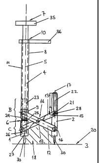
The design of the system per this invention Illustrated In fig. I encompasses
a first connecting
element 1, with a longitudinal axis 27, that can connect to a bone fragment or
vertebra, and a second
longitudinal connecting element 2, with a longitudinal axis 17, that can
connect to another bone
fragment or vertebra. The longitudinal axes 17,27 of the connecting elements
define a plane 18. On
the side facing the bone or implant the connecting elements 1, 2 are equipped
with points 30 which
can be brought up against bone fragments, vertebrae or implant sections and
which, when the system
is actuated, move along a straight line 3 positioned in the plane 18 and
extending perpendicular to
the longitudinal axes 17, 27. In addition, the second connect9ng element 2 can
be moved relative to
the tirst connecting element 1 in a manner whereby the longitudinal axis 17
travels along the plane
18 parallel to the longitudinal axis 27. For manipulating the system per this
DC1- 330585.1
---'--t------ -.._---_ . _
CA 02432516 2003-06-10
WO 01/41652 PCT/CH99/00598
6
invention, the system is further equipped with a longitudinal support 4 which
extends coaxially with
the longitudinal axis 27 of the first connecting element 1 and, having a
longitudinal axis 5 concentric
with the longitudinal axis 27, features a back end 7 as well as a front end 6
that can be connected to
the first connecting element 1. In this design, the longitudinal axis 5
extends along the plane 18. A
tubuiar sleeve 8, extending coaxially with the longitudinal axis 5 and
provided with a coaxial end-to-
end bore 11, permits the movement of the sleeve 8 coaxially with the
longitudinal axis 5 along the
longitudinal support 4. The sleeve 8 indudes a forward end piece 9 that faces
the first connecting
element 1, and a rearward end piece 10. The movement of the two connecting
elements 1, 2 relative
to each other is generated by way of a first lever 12 that connects the
forward end piece 9 to the
second connecUng element 2 and whose longitudinal axls 15 extends essentially
parallel to the plane
18, said lever 12 oonnecting in pivotable fashion to the forward end piece 9
and to the second
connecting element 2 in such fashion that, relaKve to the forward end piece 9
and to the second
connecting element 2, the lever 12 can be swiveled, causing the longitudinal
axis 15 to move parallei
to the plane 18, while a second lever 13, with a longitudinal axis 16
extending essentially parallel to
the plane 18, Is pivotally connected to the first connecting element I and to
the second connecting
element 2, whereby the longitudinal axis 15 can be rotated parallel to the
plane 18. The longitudinal
axes 15,16 of the two levers 12, 13 interse<t at a crossover point 19 and are
mutually connected via
a swivel joint 14 located at the Intersecting point 19. The scissor-like
configuration of the levers 12,
13 makes It possible for a relative movement between the forward end piece 9
and the first
connecting element I parallel to the longitudinal axis 5 to effect a movement,
parallel to the
longitudinal axes 17 and 27, between the first and the second connecting
elements parallel to the
straight line 3 that extends parallel to the plane 18 and perpendicular to the
longitudinal axis 5.
The second connecting element 2 contains a guide 22 whereby the rotation of
the second iever 13
relative to the second connecting element 2 Is made around the longitudinal
axis 28 of a pin 21 that
is movable within the guide 22. This guide 22 extends parallel to the
longitudinal axis 17 and has a
length of A, permitting the pin 21 to move in the guide 22 parallel to the
longitudinal axis 17.
DCI - 33osas.l
____--, _ - --- _
CA 02432516 2003-06-10
WO 0914165Z
PCT/CH99100598
7
The longitudinal support 4 is provided, in an area B opposite the forward end
piece 9, with a first male
thread 23 and the forward end piece 9 is provided with a female thread 24
matching the male thread
23. The longitudinal support 4 Is additionaqy provided, In an area C at its
front end 5 that can be
connected to the first connecting element 1, with a second male thread 25 and
the first connecting
element 1 is attached to the front end 5 of the longitudinal support 4 via a
female thread 26 that
matches the second male thread 25. The male threads 23 and 25 on the
longitudinal support 4
feature a mutually opposite pitch, with the male thread 25 in area C being a
right-hand thread and the
male thread 23 In area B being a left-hand thread. in analogous fashion, the
femaie threads 24, 26
In the forward end piece 9 and In the first connecting element I have a
mutually opposite pitch. As
a result, when the longitudinal support 4 is rotated around the longitudinal
axis 5, the forward end
piece 9 of the sleeve 8 and the first connecting eiement I will move toward or
away from each other,
depending on the direction of rotation of the longitudinal support 4. This
reiative movement of the
forward end piece 9 and the first connecting element I results in the relatlve
movement between the
two connecting elements 1, 2. For a rotation between the longitudinal support
4 and the sleeve 8, the
back end 7 of the longitudinal support 4 Is provided with a first handle 35
and the back end 10 of the
sleeve 8 on its part is provided with a second handle 36.
The longitudinal support 4 and the first connecting element I may be provided
with bores extending
coaxially with their longitudinal axes 5, 27, permitting the inserdon of a
screwdriver through these
bores. Similarly, the second connecting element 2 may be provided with a bore
coaxially with its
longitudinal axis 17, again permitting the Insertion of a screwdriver through
that bore.
The design version of the system according to this invention illustrated in
fig. 2 differs from the design
in fig. I only in that the.longitudinal axes 15, 16 of the two levers 12, 13
intersect at the far end,
respectively reiative to the forward end piece 9 and the first connecting
element, of the levers 12,13.
Accordingly, the swivel joint 14 connecting the two levers 12, 13 is kacated
at these ends.
DCi -330585.1
CA 02432516 2003-06-10
WO 01/41652 PCT/CH99/00598
8
The levers 12, 13 are essentially of the same length. The second connecting
element 2 is rigidly
attached to the first iever 12, with the longitudinal axis 16 of the lever 12
and the longitudinal axis 17
of the second connecting element 2 intersecdng at an angle. When this design
version of the system
according to the invention is actuated, the connecting elements 1, 2 do not
move with their
longitudinal axes 17,27 remaining parallel. Instead, the aonnecdng elements 1,
2 move along a curve
extending along the plane 18. It Is possible, however, to define on the second
connecting element 2
a point X which moves essentially along a straight line 3 parallel to the
plane 18. The connecting
elements 1, 2 are equipped with U-shaped plates 32 that can be brought in
contact with impiant or
graft sections.
Fig. 3 depicts a design version of the system according to this invention that
differs from the design
per fig. 2 only to the extent that the longitudinal support 4 can be moved In
the sleeve 8 para8ei to the
longitudinal axis 5 and that Its front end 6 is supported In the first
connecting element I in an axially
fixed positjon reiative to the iongitudinat axis 27 whiie pemnitHng rotation
around the longitudinal axis
27. in this fashion, the reiative movement between the longitudinal support 4
and the sleeve 8
constitutes a purely axial shift attainable by pushing the handles 35 and 36
toward or, respectiveiy,
away from each other. The rotatable yet axially fixed attachment of the
longitudinal support 4 in the
first connecting element I is obtained by means of a set-screw 34 that Is
screwed into the first
connecting element 1 and'protrudes Into a corresponding groove 33 In the
longitudinal support 4.
The motion transfer mechanism between the longitudinal support 4 and the
sleeve 8 can just as easily
be employed in the system per this invention ifiustrated in fig. I
Fig. 4 Is a partial view of a design version of the system according to this
invention, for instance the
design per fig. 3, In which the iongitudinat support 4 and the sleeve 8 can be
shifted, by means of a
iever mechanism 29, both parallel to the longitudinal axis 5 and reiative to
each other. Attached to the
ends 7 and 10 of the iongitudinai support 4 and the sleeve 8, In a position
perpendicuiar to the
longitudinal axis 5, are fixed levers 37 and 38 which by means of a pincer
mechanism can be
DCi -330585.1
CA 02432516 2003-06-10
WO 01/41652 PCT/CH99/00598
9
moved toward or away from each other. The pincer ievers 42 and 43 are attached
to the fixed ievers
37 and 38 via swivei jointa 39 and 40 and intersect at a common swivei joint
41, whereby a squeezing
of the pincer ievers 42 and 43 causes the ievers 37 and 38 to move toward each
other. A spring 44
positioned between them serves to pull the pincer ievers 42 and 43 apart.
:..
DCI - 39053S.1
_ _,-----~.,