Note: Descriptions are shown in the official language in which they were submitted.
CA 02432703 2003-06-18
-1-
TITLE OF THE INVENTION
Joint assembly for chimney components
FIELD OF THE INVENTION
The present invention relates to a joint assembly for end-wise connection of
two
chimney components.
BACKGROUN~ OF THE INVENTION
Chimney systems permit the exhaust of combustion gases, under positive,
negative or neutral pressure, emanating from a variety of appliances
including,
but not limited to, diesel engine and gas turbine exhausts, industrial oven
exhausts, restaurant grease ducts, boilers, incinerators, etc.
The various components of known factory-built positive pressure chimney
systems include lengths, expansion joints, tees, elbows, etc. These components
typically have a flange-to-flange end at there joining point. These flanges
are
joined together by aligning the flanges together. They are then joined
together
by means of a v-shaped assembly band, which is clamped around the flanges of
both parts. A sealant is applied in the groove of the v-band before it is
clamped
to the flanges.
OBJECTS AN~ STATEMENTS OF THE INVENTION
It is an object of the present invention to provide an improved joint assembly
for
end-wise connection of two chimney components.
It is also an object of the present invention to provide a joint assembly for
end-
wise connection of two factory-built chimney components wherein the two
components slide into one another thereby avoiding necessity to align the
parts
and providing ease of installation on horizontal runs where heavier parts are
easily slipped into one another avoiding excessive supporting of the weight at
the
time of joining.
CA 02432703 2003-06-18
-2-
It is also an object of the present invention to provide an inner tubular
collar for
protection of the joint from condensation and rain therefore protecting the
sealant
from ware due to prolonged exposure to gas condensate and water.
It is a further object of the invention to provide a thermal wall at the point
of
joining to provide added protection to the sealant from high temperatures. By
lowering fihe thermal exchange from inner flue gases to the sealant, longevity
of
the sealant and therefore of the joint will be improved preventing flue gases
from
escaping the outer wall of the chimney components.
The present invention therefore relates to a joint assembly for end-wise
connection of two chimney components wherein each component has an open
end section with a flange extremity; it comprises:
an inner tubular collar having one end insertable in one end section of a
first chimney component and an opposite end insertable in one end section of a
second chimney component;
a tubular band made of ceramic fiber mounted exteriorly to the collar; and
connection means fixedly securing the flanged extremity of the first
chimney components to the flanged extremity of the second chimney component
so as to secure the end sections to one another with the collar and band
mounted
therein.
In one form of the invention, the connection means include sealing means for
adhesively mounting the flanged extremities to one another.
In another form of the invention, the connection means further include an
assembly band mounted exteriorly to the flange extremities .sealed to one
another.
Other objects and further scope of applicability of the present: invention
will
become apparent from the detailed description given hereinafter. It should be
understood, however, that this detailed description, while indicating
preferred
embodiments of the invention, is given by way of illustration only, since
various
CA 02432703 2003-06-18
-3-
changes and modifications within the spirit and scope of the invention will
become apparent to those skilled in the art.
BRIEF DESCRIPTION OF TFIE DRi4VIIINGS
Figure 1 is a elevational view showing a joint assembly made in accordance
with
the present invention prior to an interconnection of two chimney components;
Figure 2 is an elevational view showing the two chimney components joined to
one another;
Figure 3 is an enlarged view of the assembly band and of the attaching bands;
and
Figure 4 is an illustration of one half of an attaching band.
DESCRIPTION OF PREFERRED EMBODIMENTS
Referring to figure 1, there is shown a joint assembly, generally denoted 10,
for
connecting two chimney components, identified as A and B. fn the embodiment
illustrated, the components are two lengths of the double wall chimney
construction consisting of an outer wall 12 and an inner wall 14 for chimney A
and an outer wall 16 and an inner wall 18 for chimney B. The inner wall 14, 18
of each chimney component defines an open end section 20, 22 having a
diameter slightly greater than the diameter of the remaining portion of the
wall.
Each end section 20, 22 has a flanged extremity 24, 26.
The joint assembly 10 comprises an inner tubular collar 28 having one end 30
insertable in the open section 20 of the chimney component A and an opposite
end 32 insertabie in the end section 22 of chimney B (as indicated by the
arrows
34).
CA 02432703 2003-06-18
-4-
A tubular band 36 made ofi ceramic fiber is circumferentially and exterioriy
mounted over part of the outer wall of the collar 28.
The end-wise connection of chimney A to chimney B will now be described.
First,
the collar 28 is inserted in the end connection 20 of chimney A. The upper end
30 of the collar is welded (seam welded or spot welded) to the inner wall of
the
end section 20. Thereafter, the band 30 of ceramic fiber is inserted between
the
collar 28 and the end section 20 and is fixed therein by means of an adhesive
40.
Subsequently, a sealant 42, such as a silicone, is applied circumfierentially
on the
flanged extremity 26 ofi the chimney component B. chimney component A with
the joint assembly 10 is then moved as indicated by arrows 34 to engage the
chimney component B.
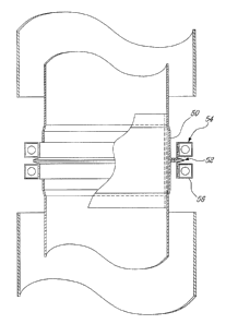
Referring to fiigure 2, where the two chimney components A and B are shown
engaged to one another, the interconnection is further secured by means of an
assembly band 50, having a V-shaped mid section 52, to which a pair of
attaching bands 54 and 56 are mounted exteriorly. The pair of attaching bands
54 and 56 are welded to the assembly band 50. A silicone material 58 is
deposited in the V-shaped section 52 of the assembly band 50. The assembly
band 50 and attaching bands 54 and 56 are placed in a manner that the flanged
extremities 24, 26 sealed to one another are received within the mid section
52
of the assembly band to which they are further sealed due to the adhesive 58.
Figure 4 illustrates the construction of the extremities 50 and 62 of an
attaching
band so that a full ring may be formed.
Although the invention has been described above with respect to one specific
form, it will be evident to a person skilled in the art that it may be
modified and
refined in various ways. It is therefore wished to have it understood that the
present invention should not be limited in scope, except by the terms of the
following claims.