Note: Descriptions are shown in the official language in which they were submitted.
CA 02432974 2003-06-20
BAGLESS VACUUM CLEANER WITH HELICAL PASSAGEWAY
FIELD OF THE INVENTION
This invention relates generally to vacuum cleaners and, more particularly, to
bagless vacuum cleaners.
BACI~GRO OF THE INVENTION
Bagless vacuum cleaners have become very popular over the last several years.
This popularity is due in large part to the ease with which dust and dirt can
be removed from
such vacuum cleaners. In old style cloth bag-containing vacuum cleaners, dust
and dirt
removal is a difficult and awkward process, frequently requiring the user to
extend his or her
hand into the cloth bag to physically disengage dust clumps. Vacuum cleaners
using disposable
B
CA 02432974 2003-06-20
liner bags minimize the problems associated with cloth bags, but the use of
such vacuum
cleaners requires the continuous replenishment and installation of disposable
liner bags. (Also,
owners of older model disposable liner bag-containing vacuum cleaners often
find it difficult to
locate a source of properly sized replacement liner bags.)
Contrary to these problems associated with bag-containing vacuum cleaners,
dirt
and dust vacuumed up using bagless vacuum cleaners is conveniently deposited
into an easily
removable permanent container, from which dust and dirt can be disposed of
without the effort
associated with cloth bag-containing vacuum cleaners and without having to
continually
purchase and reinstall disposable liner bags.
The efficiency of bagless vacuum cleaners is dependent upon the "strength" of
the cyclone formed within the dust extraction and collection unit of the
vacuum cleaner. The
stronger the cyclone, the better the separation of dust from the incoming dust-
laden air.
Accordingly, there is a need for a bagless vacuum cleaner having improved
cyclonic action.
SUM1~IARY
The invention satisfies this need. The invention is a vacuum cleaner having
(a)
a chassis having a base unit and a housing unit, the base unit having an am
inlet and roller
means for moving the vacuum cleaner across a flat surface, (b) an air blower
disposed within
the chassis, (c) a removable dust extraction and collection unit disposed
within the housing
unit, the dust extraction and collection unit comprising (i) an enclosed inlet
chamber, the inlet
chamber being substantially cylindrical in shape, the inlet chamber comprising
a bottom wall,
at least one generally vertical sidewall, a cover, an upper section and a
lower section, and (ii)
2
CA 02432974 2003-06-20
an enclosed outlet chamber suspended downwardly from the cover and disposed
concentrically
within the upper section of the inlet chamber, the outlet chamber having a
bottom wall and at
least one generally vertical side wall, the at least one sidewall having a
plurality of inlet
apertures, the inlet apertures being disposed in a band around the at least
one sidewall, and {d)
duct work for serially connecting in fluid communication the air inlet in the
base unit, the inlet
chamber, the outlet chamber and the air blower, wherein the cover comprises a
central portion
and a peripheral portion, the central portion defining an air outlet opening
for the outlet
chamber and the peripheral portion defining an air inlet opening for the inlet
chamber, the
peripheral portion further defining a helical passageway fox directing
incoming air to the inlet
chamber in a downwardly directed cyclone flow pattern.
In one embodiment, the helical passageway extends at least once around the
peripheral portion of the cover. Typically, the helical passageway extends
between once and
twice around the peripheral portion of the cover.
The helical portion typically comprises an upstream section and a downstream
section. In one embodiment, the upstream section comprises a downwardly
slanted top wall
and a pair of spaced apart side walls. In a typical embodiment, such upstream
section has at
least one cross-section defining an area between about 5 cmz and about 8 cm2,
most typically
between about 6 cm2 and about 7 cm2.
DRAWINGS
These features, aspects and advantages of the present invention will become
better understood with regard to the following description, appended claims
and accompanying
figures where:
3
CA 02432974 2003-06-20
Figure 1 is a perspective view of a vacuum cleaner having features of the
invention;
Figure 2 is a rear view of the vacuum cleaner illustrated in Figure 1;
S
Figure 3 is a diagrammatic cutaway view of the vacuum cleaner illustrated in
Figure 1;
Figure 4 is a cross-section of a dust extraction and collection unit in the
vacuum
cleaner illustrated in Figure 1;
Figure 5 is an exploded perspective view of the cover of the dust extraction
and
collection unit in the vacuum cleaner illustrated in Figure 4; and
Figure 6 is a second exploded view of the cover illustrated in Figure 5.
DETAILED DESCRIPTI(.~1~1
The following discussion describes in detail one embodiment of the invention
and several variations of that embodiment. This discussion should not be
construed, however,
as limiting the invention to those particular embodiments. Practitioners
skilled in the art will
recognize numerous other embodiments as well.
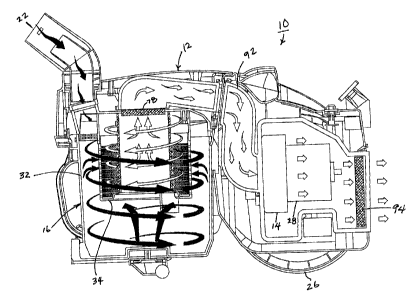
The invention is a vacuum cleaner 10 having features which improve upon
vacuum cleaners disclosed in my prior patents, U.S. Pat. No. 6,269,518 P1 and
U.S. 6,484,350. As illustrated in Figures 1-4, the vacuum cleaner 10 has a
chassis 12, an air
blower 14 and a dust extraction and collection unit 16. The vacuum cleaner 10
can be a
4
CA 02432974 2003-06-20
canister-style vacuum cleaner as illustrated in the drawings, or it can be of
an upright style (not
shown).
The chassis 12 comprises an air inlet 22 wherein dust and dirt is sucked up
into
the chassis 12.
The chassis 12 further comprises roller means for moving the vacuum cleaner
across a flat surface. In the embodiment illustrated in the drawings, such
roller means
include a pair of wheels 26 disposed on apposite sides of the chassis 12.
The air blower 14 is disposed within the chassis 12. The air blower 14 is
typically an electrically driven air blower having a capacity between about 50
m3lhour and
about 200 m3/hour. A typical electrical motor 28 for driving the blower
operates on ordinary
house current and has a power capacity between about 800 watts and about 2000
watts.
The dust extraction and collection unit 16 is disposed within the chassis 12.
The
dust extraction and collection unit 16 comprises an enclosed inlet chamber 32
and an enclosed
outlet chamber 34. The dust extraction and collection unit 16 is illustrated
in detail in Figures
3-6.
The inlet chamber 32 is substantially cylindrical in shape with an internal
diameter between about 130 mm and about 200 nun, preferably between about 150
mm and
about 180 mm. The inlet chamber 32 comprises a body portion 35. The body
portion 35 has
a bottom wall 36, and at least one generally vertical sidewall 38. The at
least one sidewall 38
2~ typically has an interior height between about 200 mm and about 250 mm,
most typically
between about 220 mm and about 230 mm.
5
CA 02432974 2003-06-20
The inlet chamber 32 has an upper section 42 and a lower section 44. The inlet
opening 46 of the inlet chamber 32 is configured to provide the ingress of
dusty air into the
inlet chamber 32 in tangential fashion wherein the ingressing dusty air is
caused to downwardly
spiral around the internal surface 48 of the at least one inlet chamber body
portion sidewall 38.
The inlet chamber 32 is preferably reversibly installable and deinstallable
within
the chassis 12. In the embodiment illustrated in the drawings, the inlet
chamber 32 is
reversibly installable and deinstallable within the chassis 12 via a snap-on
connection between
the inlet chamber walls and the walls of the chassis 12. In another embodiment
(not shown),
the inlet chamber 32 is reversibly installable and deinstallable within the
chassis 12 using a
press-fit connection.
The inlet chamber 32 further comprises a removable cover 47. The cover 47
comprises a central portion 60 and a peripheral portion 62. As illustrated in
Figures 5 and 6,
the cover 47 comprises a base 64 and a peripheral insert 82. The base 64 has a
top wall 83
and a downwardly depending circular side wall 84. The cooperation of the
circular side wall
84 and the peripheral insert 82 defines a helical passageway 85 having an
upstream section 86
and a downstream section 88. The upstream section 86 is attached in fluid
tight
communication with the inlet opening 46. The upstream section 86 comprises a
slanted top
wall 90 and a pair of spaced apart side walls 96, the outer of which is
provided by the at least
one side wall 84 of the base 64. Typically, the vertical height of the pair of
spaced apart side
walls 96 is about 2.5 cm, and the side walls 96 are spaced apart by a distance
of about 2.5 cm.
Thus, at least one cross-section of the upstream section of the helical
passageway 8S defines an
area of between about 5 cm2 and about 8 cm2, most typically between about 6
cm2 and about 7
cm2. The peripheral insert 82 comprises a circular collar 98 with a helical
flange 100
extending around it. The helical flange 100 provides the slanted top wall 90
in the upstream
section 86. Typically, the helical flange 100 extends more than once around
the collar 98,
most typically between about once and about twice around the collar 98.
s
CA 02432974 2003-06-20
The helical passageway 85 guides the incoming air to the inlet chamber 32 over
a longer distance than the incoming air is guided in known prior art units.
This results in
higher air inlet velocities which, in turn, results in higher inlet air
accelerations. The net result
of the higher air inlet velocities and accelerarions is a much stronger
cyclone within the inlet
chamber 32 than is possible in known prior art units.
The outlet chamber 34 is disposed concentrically within the upper section 42
of
the inlet chamber 32. The outlet chamber 34 is suspended from the top wall 83
of the cover
47. The outlet chamber 34 has a bottom wall 50 and at least one generally
vertical sidewall
54. The at least one sidewall 54 has an interior height between about 50 mm
and about 100
mm, preferably between about 80 mm and about 90 mm.
The at least one sidewall 54 of the outlet chamber 34 is perforated with a
plurality of inlet apertures 56, each defining an area between about 3 mm2 and
about 30 mm2.
In a typical embodiment, the at least one sidewall 54 defines between about
1000 and about
1500 inlet apertures 56, preferably between about 1300 and about 1400 inlet
apertures 56.
Typically each of the inlet apertures 56 is separated from adjoining inlet
apertures 56 by a
distance of between about 1.5 mm and about 5 mm. The inlet apertures 56 are
preferably
disposed in a band 58 around the sidewalk 54 of the outlet chamber 34.
'Typically, the band
58 has a width between about 20 mm and about 50 mm, preferably between about
30 mm and
about 40 mm. The band 58 defines a median line (not shown which divides the
uppermost
apertures 56 from a substantially equal number of lowermost apertures 56.
Typically, the
median line is disposed between about 30 mm and about 100 mm above the bottom
wall 50 of
the outlet chamber 34, preferably between about 50 mm and about 60 mm above
the bottom
wall 50.
In the embodiments illustrated in the drawings, the bottom wall 50 of the
outlet
chamber 34 has an X-shaped wall '15 which projects vertically above the bottom
wall 50. This
CA 02432974 2003-06-20
X-shaped wall 75 supports the cylindrical filter 76. Typically, such
cylindrical filter 76 is
made from polypropylene, paper, ceramic or polytetrafluoroethylene having a
thickness
between about 1.5 mm and about 5 mm.
The cylindrical filter 7b is suspended from the central portion 60 of the
cover,
such that the cylindrical filter 76 is disposed vertically and concentrically
within the outlet
chamber 34.
The central portion 60 of the cover 47 defines a top wall opening 78 for the
outlet chamber 34.
In a preferred embodiment, the outlet chamber 34 comprises a planar filter 80
disposed across the top wall 78 opening of the outlet chamber 34. In a typical
embodiment,
such planar filter 80 is made from sponge, fibrous polyethylene, fibrous
polypropylene or
paper, and typically has a thickness between about 5 mm and about 15 mm.
The invention further comprises duct work 92 for serially connecting in fluid
communication the air inlet 22 in the base unit 18, the inlet chamber 32, the
outlet chamber 34
and the air blower 14.
It is very important that all such duct work 92 and all connection points
witb.in
the duct work and between various components in the system and/or the duct
work 92 be well-
sealed. Even small leaks within the system can markedly decrease efficiency
and increase
power requirements.
In a preferred embodiment, a blower filter 94 is operatively disposed
downstream of the air blower 14. Preferably, such blower filter 94 is a HEPA
filter.
8
CA 02432974 2003-06-20
The invention has been found to provide a vacuum cleaner with all the
conveniences of prior art vacuum cleaners, but with increased dust removal
efficiency and
without excessive mechanical complexity and resulting expense of manufacture.
Having thus described the invention, it should be apparent that numerous
structural modifications and adaptations may be resorted to wifhout departing
from the scope
and fair meaning of the instant invention as set forth hereinabove and as
described hereinbelow
by the claims.
9