Note: Descriptions are shown in the official language in which they were submitted.
CA 02433040 2003-06-23
WO 03/034928 PCT/US02/34304
MULTIPLE HEMOCLIP SYSTEM FOR AN ENDOSCOPE
CROSS-REFERENCE TO RELATED APPLICATION
This application claims the benefit of U.S. Provisional Patent Application
No. 60/347,832, filed on October 24, 2001.
FIELD OF THE INVENTION
The present invention relates to a system for clipping body tissue, such as a
system for introducing a clip for hemostasis ("hemoclip") endoscopically in
the GI tract.
BACKGROUND OF THE INVENTION
One known system for introducing a hemoclip endoscopically is shown in U.S.
Patent No. 3,958,576 assigned to Olympus Optical Co. Ltd. of Japan. See also
Japanese
Patent Publication No. 04102450 and U.S. Patent No. 5,766,189. Each of these
devices is
used to insert a single clip, and includes a series of mechanical members to
insert, eject
and close or clamp the clip at a desired location, such as for hemostasis in
the GI tract.
SUMMARY OF THE INVENTION
The present invention provides an improved hemoclip system. In one aspect of
the invention multiple clips can be applied internally by way of a
conventional endoscope
without removal and reinsertion of a clip-retaining member. The system
provides good
control of the rotated position of a clip, with little backlash, for
convenient and reliable
placement of a clip or clips.
BRIEF DESCRIPTION OF THE DRAWINGS
The foregoing aspects and many of the attendant advantages of this invention
will
become more readily appreciated as the same become better understood by
reference to
the following detailed description, when taken in conjunction with the
accompanying
drawings, wherein:
FIGURE 1 is an enlarged side elevation of the distal portion of a multiple
hemoclip system for an endoscope in accordance with the present invention with
parts
shown in section;
FIGURE 2 is a distal end elevation of the device of FIGURE 1;
FIGURE 3 is a transverse section along line 3--3 of FIGURE l, with parts
removed;
FIGURE 4 is a top plan of the distal end portion of the device with parts
shown in
section;
1
CA 02433040 2003-06-23
WO 03/034928 PCT/US02/34304
FIGURE 5 is a top perspective of a hemoclip usable in the system of the
present
invention;
FIGURE 6 is a top perspective of a second embodiment of a hemoclip usable in
the system of the present invention;
FIGURE 7 is a top perspective of a third embodiment of a hemoclip usable in
the
system of the present invention;
FIGURE 8 is a side elevation of a fourth embodiment of a hemoclip usable in
the
system of the present invention;
FIGURE 9 is a vertical section along line 9--9 of FIGURE 5,;
FIGURE 10 is a vertical section corresponding to FIGURE 9 showing aspects of
an alternative embodiment of a hemoclip usable in the system of the present
invention;
FIGURE 11 is a vertical section corresponding to FIGURE 9 showing aspects of a
further embodiment of a hemoclip usable in the system of the present
invention;
FIGURE 12 is a diagrammatic top perspective of the proximate portion of a
multiple hemoclip system for an endoscope in accordance with the present
invention;
FIGURE 13 is a side elevation of the proximate portion shown in FIGURE 12,
with parts broken away;
FIGURE 14 is a top plan of a second embodiment of a proximate portion of a
multiple hemoclip system in accordance with the present invention, with parts
broken
away;
FIGURE 15 is a top plan of a third embodiment of a proximate portion for a
system in accordance with the present invention, with parts broken away;
FIGURE 16 is a top plan of a fourth embodiment of proximate portion for a
system in accordance with the present invention, with parts broken away; and
FIGURE 17 is a top plan of a fifth embodiment of a proximate portion for a
system in accordance with the present invention, with parts broken away.
DETAILED DESCRIPTION OF THE PREFERRED EMBODIMENT
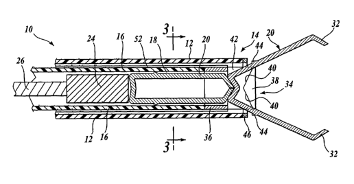
With reference to FIGURES 1-4, a hemoclip system 10 in accordance with the
present invention includes an elongated outer tube or shaft 12 which may be
inserted
through a conventional scope for positioning a distal, clip-carrying portion
14 of the shaft
at a desired location of the body, such as a location of bleeding to be
clamped. Such
elongated outer tube or shaft 12 can be manufactured from an extruded
biocompatible
polymer or other suitable material. The proximate end portion of the outer
shaft connects
2
CA 02433040 2003-06-23
WO 03/034928 PCT/US02/34304
to a handle as described below with reference to FIGURES 12-17 for external
control of
the relatively movable component parts of the distal portion 14.
An inner shaft 16 is slideably received within the outer shaft 12, and also
may be
manufactured from an extruded biocompatible polymer or other suitable
material. The
longitudinal position of the inner shaft 16 relative to the outer shaft 12 can
be adjusted.
The cross-sectional shape of the major portion of the inner shaft 16 is best
seen in
FIGURE 3. A generally rectangular bore or cavity 18 is sized for receiving
spring
clips 20 of the type described in more detail below. To prevent stretching of
the inner
shaft, support wires 22 can be embedded in it at opposite sides of the central
cavity or
recess 18.
The cavity 18 is shaped for reception of spring clips 20. Such clips fit close
within the cavity 18 but are freely slideable therein. In general, several
clips axe
preloaded in the distal end of the inner shaft, such as three or more clips
placed end to
end. The clips are dispensed, in part, by a pusher block 24 received in the
recess 18
proximate to the clips. The pusher block can be moved distally and proximally
by
manipulation of an attached core wire 26. Wire 26 extends through the inner
shaft 16 and
is slidable therein.
The clips 20 can be manufactured from a metal with spring arid/or memory
properties, such as stainless steel or Nitinol. With reference to FIGURE 5,
the basic
shape is a thin band plate, bent toward its center or web 28 to form a long U
with
elongated opposing jaws 30. The ends of the jaws are bent inward to form teeth
32 that
face each other. The inner ends of the teeth can be sharpened to form grabbing
hooks.
Returning to FIGURES 1 and 2, a clip opener component 34 is secured at the
distal end of the inner shaft 16, such as by attachment to the strengthening
wires 22
(shown in the cross-section of FIGURE 3). Such wires preferably extend the
full length
of the inner shaft. The clip opener includes a continuous shell 36 at its
proximate end and
two side pieces 38 at its distal end. As seen in FIGURE 4, the proximate
portion or
shell 36 tapers inward at opposite sides 37 (this tapering and other
dimensions are
exaggerated in the drawings for ease of illustration and description). The
distal or leading
ends of the clip jaws are similarly tapered. A clip 20 is "loaded" by forcing
it forward,
using the pusher block 24. This has the effect of wedging the side pieces 38
apart until
the proximate or trailing end of the clip clears the tapered sides 37. After a
short travel of
the clip distally, the opening between the clip jaws formed by the teeth 32
engage the
3
CA 02433040 2003-06-23
WO 03/034928 PCT/US02/34304
distal end portions of the side pieces 38 which project part way into the path
that a clip
follows when driven forward by the clip pusher 24. See, for example, the
position of the
side pieces 38 in FIGURE 2. The adjacent edges of the side pieces 38 are
spaced apart
transversely but are close enough together so as to be engaged by the tapered
leading
ends of the clip 20. Each side piece has proximate wedge surfaces 40 (FIGURE
1)
angled outward from the center line of the device and configured such that the
distal ends
of the clip jaws are wedged apart when the pusher block moves the clip against
the
opener surfaces 40. Consequently, as a clip is forced forward along the cavity
18 of the
inner shaft 16, the clip teeth 32 and jaws 30 are wedged apart to the
condition illustrated
at the right of FIGURE l, contrary to the natural memory or spring
characteristics of the
clip. This action tends to spread the side pieces 38 apart until the central
portion or
web 28 of the clip fits within an intermediate cavity portion 42 of the clip
opener 34.
When this position is reached, the clip is reliably held in the clip opener
with its jaws
open.
The opened clip can be moved by manipulation of the outer shaft or tube 12,
and
can be rotated by manipulation of the inner tube or shaft 16. When a desired
site and
orientation are reached, such as a bleeding site, the clip can be ejected by
withdrawing the
inner shaft 16 relative to the outer shaft 12. With reference to FIGURE 1,
projections 44
on the outer sides of the clip jaws 30 are positioned to engage against a
metal collar 46
provided at the end of the outer shaft 12. With reference to FIGURE 2, as the
inner shaft,
including clip opener 34, is retracted within the outer tube, the opener side
pieces 38 are
wedged apart, in the direction of the arrows 48. In addition, the clip edges
can have
weakening nicks 50 (shown only in FIGURE 2) that allow the metal of the jaws
to bend
inward as the jaws move past the opener side pieces 38, until the clip is
released and its
teeth 32 move towaxd each other to clamp the tissue at the desired site, due
to the inherent
spring or memory characteristics of the clip. After dispensing of one clip,
the next clip
can be moved into position by manipulation of the core wire 26 and attached
pusher 24.
With reference to FIGURE 3, the outer periphery of the inner shaft 16 can have
equally spaced ribs 52 for ease in sliding along the inner periphery of the
outer shaft 12.
The shafts and core wire 26 can be curved or bent during use, depending on the
application.
Different clip geometries may be used, as illustrated in FIGURES 5-11.
Preferably the clips axe quite wide, at least one millimeter, for maximum
spring force.
4
CA 02433040 2003-06-23
WO 03/034928 PCT/US02/34304
With reference to FIGURE 6, one of the teeth 32 can form a sharpened angular
projection
shaped to be received in a corresponding angular recess of the other tooth 32.
The web
end 28 of the clip can include a circular or helical wire spring member. With
reference to
FIGURE 7, the web portion 28 of the clip can be narrower than the main body
portion of
the jaws 30, to allow some pivoting movement of an open clip when in the
position at the
right of FIGURE 2, it being understood that the narrowed portion of the clip
web 28
would extend beyond the distal end of the outer shaft. In that case, the
shoulders formed
between the web 28 and jaws 30 could be positioned to substitute for the
projections 44.
With reference to FIGURE 8, closing force for the clip 20 can be achieved or
augmented
by a separate elastic band 52. One or more of the clip components can be
bioabsorbable,
so that the clip would automatically be released over time. The clip jaws 30
can be of
rectangular cross-section (FIGURE 9) or can be arcuate (FIGURE 10) or angled
(FIGURE 11) for increased rigidity.
With reference to FIGURES 12 and 13, the proximate portion 54 of the multiple
hemoclip system in accordance with the present invention can be in the form of
a handle
having separate components for positioning the outer shaft 12 and manipulating
the inner
shaft 16 and core wire 26 connected to the clip opener and pusher,
respectively. The
parts are shown diagrammatically. The outer shaft 12 is coupled to a larger
fitting 56
leading to a bracket portion 58 that can more easily be grasped and positioned
by a user.
The inner shaft 16 is coupled to a proximate extension 60 leading to a finger
hole 62.
Most of the extension 60 is cylindrical, but an operating knob 64 is j
ournaled on a short
noncylindrical portion 66 of the extension. The knob can be turned to rotate
the inner
shaft, but is slideable along the noncylindrical portion 66. Sliding movement
of the
extension relative to the knob 64 is limited by stops 68 at both sides. Since
the knob is
held within the bracket 58, stops 68 define the maximum travel of the inner
shaft 16
inside the outer shaft 12.
The core wire 26 is coupled to a sliding spool 70. The spool is moveable fore
and
aft (distally and proximally) along the extension 60, for moving the core wire
and
attached clip pusher relative to the inner shaft 16. Thus, the proximate
portion 54 can be
manipulated to position a clip adjacent to a site to be clamped, whereupon the
spool 70 is
moved distally to slide the core wire 26 and clip pusher 24 sufficiently to
position the
distal most clip as shown at the right of FIGURE 1. Knob 64 can be used to
rotate the
inner shaft to orient the clip as desired. Only a short relative movement of
the inner and
5
CA 02433040 2003-06-23
WO 03/034928 PCT/US02/34304
outer shafts is required to eject the clip, which will relax toward its closed
position to
apply a clamping force at the desired site. Thereafter, the device need not be
removed
and reloaded. Rather, the next clip can be moved forward and the process
repeated to
secure another clip. Removal of the distal portion of the multiple hemoclip
system is not
required until the supply of preloaded clips has been exhausted.
Other proximate operating mechanisms can be used. In the embodiment of
FIGURE 14, the inner shaft 16 is coupled to the long, cylindrical extension 60
leading to
the finger hole 62, as in the previously described embodiment. Also, knob 64
is journaled
on, and slideable along, the non-circular portion 66, with such sliding
movement being
limited by stops 68. However, in the embodiment of FIGURE 14, the fitting 56
continues
to and is affixed to the spool 70. Knob 64 has opposite sides that project
through
openings in the fitting or housing 56. Relative movement of the extension 60,
such as by
use of the finger hole 62, and the spool 70 results in corresponding relative
movement of
the inner shaft 16 and outer shaft 12.
In the embodiment of FIGURE 14, the core wire 26 connects to a slide
mechanism having an external operating button 72 slideably mounted on the
spool
structure 70. Indicia 74 adjacent to the button 72 indicate the position of
the pusher block
carried by the core wire 26 at its distal end. Thus, by viewing the position
of the
button 72 relative to the indicia 74, a user will know the position of the
clips at the distal
end and also the number of clips remaining.
The embodiment of FIGURE 15 is identical to the embodiment of FIGURE 14
except for the mechanism for moving the core wire 26. In this embodiment, the
spool
portion 70 carries a rotatable dial 76 having indicia 78. The core wire 26
connects to or is
wrapped around an internal segment of the dial such that rotation of the dial
moves the
core wire 26 (and attached clip pusher) inside the inner shaft 16. The indicia
78 can be
used to determine the position of the clips at the distal end and/or the
number of clips
remaining to be dispensed.
In the embodiments of FIGURES 16 and 17, the fitting 56 connected to the outer
shaft 12 is identical to that used in the embodiment of FIGURES 12 and 13,
including the
bracket portions 58. In addition, the inner shaft 16 connects to the extension
60, with a
non-circular segment 66 on which the knob 64 is journaled, and stops 68
limiting the
relative movement of the inner and outer shafts. In the embodiment of FIGURE
16,
however, the spool section 70 is fixed to the extension 60. Core wire 26 is
moved
6
CA 02433040 2003-06-23
WO 03/034928 PCT/US02/34304
relative to the spool (and, consequently, relative to the inner shaft) by a
slide operating
mechanism of the type described above with reference to FIGURE 14. The
external
button 72 is slideable lengthwise of component 70 for moving the core wire 26,
and
indicia 74 can be used to determine the position of the clips and the number
of clips
remaining.
The embodiment of FIGURE 17 is identical to the embodiment of FIGURE 16
except for the mechanism for moving the core wire 26. In the FIGURE 17
embodiment,
a dial mechanism of the type described above with reference to FIGURE 15 is
used.
Component 70 is fixed to the inner shaft extension 60. Indicia 78 on the dial
76 indicate
the position of the clips.and the number of clips remaining.
While the preferred embodiment of the invention has been illustrated and
described, it will be appreciated that various changes can be made therein
without
departing from the spirit and scope of the invention.