Note: Descriptions are shown in the official language in which they were submitted.
CA 02433299 2008-05-13
METHOD OF JOINING CLOSED SECTION MEMBERS BETWEEN
FRAME MODULES
This application claims the benefit of U.S. Provisional Application Serial
No. 60/260,682, filed on January 11, 2001.
FIELD OF THE INVENTION
This invention relates in general to vehicle frames and more particularly to a
modular vehicle frame.
BACKGROUND OF THE INVENTION
A vehicle ladder frame typically includes a pair of transversely spaced
longitudinal side rails interconnected by a series of transverse cross
members. Various
vehicle subassemblies are mounted on the frame, such as the engine, passenger
compartment, suspension, etc.
To enhance manufacturing efficiencies, some vehicle ladder frames are
designed with a plurality of modular subassemblies. Each module subassembly
typically includes two side rail frame portions interconnected by at least one
cross
portion. The modules are formed individually and have respectively associated
vehicle
components mounted thereon. The modules are then joined and connected together
forming the full vehicle frame.
Since the modules are smaller and lighter than the whole of the vehicle frame,
the modules are easier to manipulate in a manufacturing environment.
For some applications, it is desirable to provide frame side rails that have
at
least forward portions thereof disposed in angular relation with one another.
In other words, at least the forward portions of the side rails are not
CA 02433299 2003-06-25
WO 02/055363 PCT/US02/00493
parallel to one another, but rather are angled so as to have an increasing
distance therebetween as they extend rearwardly. The angular configuration
of the side rails increases structural performance of the frame for certain
applications.
Because of the geometries and manufacturability problems involved,
modularized ladder frame assemblies with angular forward side rail members
have not been pursued.
Increased geometric and manufacturing difficulties for such an
arrangement are also introduced when closed section side rail members are
desired. Closed section or tubular side rail members are desirable,
particularly
towards the front end of a ladder frame, as such tubular frame members are
more suitable for bearing the load of the vehicle engine.
SUMMARY OF THE INVENTION
It is an object of the present invention to provide a vehicle ladder
frame that benefits from having both a modular construction and an angular
side rail configuration, at least towards the front end thereof. In accordance
with the principles of the present invention, this objective is achieved by
providing a frame assembly for a motor vehicle that includes a forward
module and a rearward module. The forward module has a pair of tubular
forward side rail portions that are interconnected by a cross portion. The
forward side rail portions are disposed at an angle with respect to one
another
such that they have an increasing distance between them as they extend
rearwardly. The rearward module has a pair of tubular rearward side rail
portions that are interconnected by a cross portion. Rearward ends of the
2
CA 02433299 2003-06-25
WO 02/055363 PCT/US02/00493
forward side rail portions are connected to associated forward ends of the
rearward side rail portions. At least one of the side rail portions has a
notch
formed therein to enable connection thereof to the side rail portion
associatively connected therewith. The notch permits an end portion of the at
least one side rail portion to be bent laterally to permit interface with the
associated side rail portion connected thereto and then be bent back to be
welded to the associated side rail portion connected thereto.
It is a further object of the invention to provide a method of forming a
modular frame assembly for a motor vehicle. This method is accomplished by
providing a forward module that has a pair of forward side rail portions
interconnected by a cross portion. The forward side rail portions are disposed
at an angle with respect to one another such that they have an increasing
distance therebetween as they extend rearwardly. A rearward module is also
provided that has a pair of tubular rearward side rail portions that are
interconnected by a cross portion. The forward module is then connected to
the rearward module by, first forming a notch in an end of at least one of the
side rail portions so as to form first and second split portions. The first
split
portion is then bent to widen the at least one of the side rail portions to
thereby
enable the end of the at least one of the side rail portions to receive an
associated end of an adjoining one of the side rail portions. Next, the first
split
portion is bent back to narrow the widened end of the at least one of the side
rail portions. The forward ends of the rearward side rail portions are then
welded to rearward ends of the forward side rail portions.
It is a further object of the invention to provide a method comprising
constructing a forward module comprising a pair of forward side rail portions
3
CA 02433299 2003-06-25
WO 02/055363 PCT/US02/00493
interconnected by a cross portion. The forward side rail portions are disposed
at an angle with respect to one another such that the forward side rail
portions
have an increasing distance therebetween as they extend rearwardly. The
forward side rail portions have associated rearward ends. The method
includes constructing a rearward module comprising a pair of rearward side
rail portions interconnected by a cross portion. The rearward side rail
portions
have associated forward ends. The method fu.rther includes connecting the
forward module with the rearward module after the modules have been
constructed. The connecting is accomplished by (a) bending at least one end
of the ends so that the rearward ends of the forward side rail portions mate
with the forward ends of the rearward side rail portions, and (b) welding the
rearward ends to the forward ends.
BRIEF DESCRIPTION OF THE DRAWINGS
Figure 1A is a top plan view of one embodiment of an angular modular
vehicle frame assembly of the present invention;
Figure 1B is a top plan view of another embodiment of an angular
modular vehicle frame assembly;
Figure 1 C is an enlarged view of the encircled portion indicated in
Figures lA and 1B;
Figure 2 is a partial top plan view of the forward and rearward modules
of the modular vehicle frame assembly of Figure 1A, shown prior to
connection;
4
CA 02433299 2003-06-25
WO 02/055363 PCT/US02/00493
Figure 3A is a partial top plan view of the rearward module shown in
Figure 2, with the notches formed within forward ends of the rearward side
rail portions;
Figure 3B is a perspective view of one forward end portion of an
associated rearward side rail portion shown in Figure 3A;
Figure 3C is a perspective view of one forward end portion of an
associated rearward side rail portion, wherein the side rail portion has a C-
shaped sectional configuration;
Figure 4 is a partial top plan view of the forward and rearward modules
shown in Figure 3A, shown with first split portions bent laterally outwardly;
Figure 5 is a partial top plan view of the forward and rearward modules
shown connected with one of the first split portions deflected to its original
position and welded;
Figures 6-8 are top views of alternate embodiments of the notch
formed in one of the side rail portions;
Figure 9 is a top view of the forward and rearward modules with the
notches formed in the forward side rail portions;
Figure 10 is a top view of the forward and rearward modules shown in
Figure 9 with the first split portions deflected laterally inwardly; and
Figure 11 is a top view of the forward and rearward modules shown in
Figure 10 connected with one of the first split portions deflected to its
original
position and welded.
DETAILED DESCRIPTION OF THE INVENTION
5
CA 02433299 2003-06-25
WO 02/055363 PCT/US02/00493
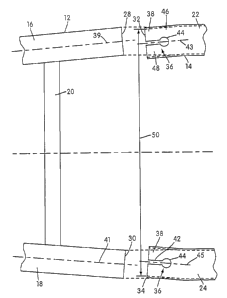
Figure 1A shows a frame assembly 10, embodying the principles of the
present invention, which includes a forward module 12 and a rearward module
14. The forward module 12 has a pair of forward side rail portions 16, 18 that
are interconnected by one or more cross portions 20. The forward side rail
portions 16, 18 are disposed at an angle with respect to one another such that
they have an increasing distance between them as they extend rearwardly.
The rearward module 14 has a pair of rearward side rail portions 22, 24 that
are interconnected by at least one cross portion 26. Rearward ends 28, 30 of
the forward side rail portions 16, 18, respectively, are connected to
associated
forward end portions 32, 34 of the rearward side rail portions 22, 24,
respectively. In the embodiment shown in Figures 1A-5, the forward end
portions 32, 34 of the rearward side rail portions 22, 24 are provided with a
notch 36 to enable connection of the rearward side rail portions 22, 24 with
the
forward side rail portions 16, 18, as will be described. The notch 36, shown
in
detail in Figure 1C, permits first split portions 46 of the forward end
portions
32, 34 of the rearward side rail portions to be bent laterally outwardly
(splayed
open) to permit interface with the associated rearward ends of the forward
side
rail portion connected thereto and then be bent back to be welded as will be
described in greater detail later.
In one embodiment, the entire extent of the rearward side rail portions
22, 24 are disposed at an angle with respect to one another such that they
have
an increasing distance between them as they extend rearwardly, as shown in
Figure 1B. The angle between rearward side rail portions 22 and 24 is the
same angle as the forward side portions 16, 18 are disposed at with respect to
each other. Alternately, as shown in Figure 1A, it is contemplated that only
6
CA 02433299 2003-06-25
WO 02/055363 PCT/US02/00493
the forward portions of the rearward side rails are disposed at an angle with
respect to one another, such angle also being the same angle at which the
forward side rails 16, 18 are disposed with respect to one another, with the
greater extent of the rearward side rail portions 22, 24 being arranged
generally parallel to each other. The forward and rearward modules 12, 14 are
then formed by joining respective side rail portions to each other with
associated cross portions. The forward and rearward side rail portions may be
formed by a roll forming process. It is also contemplated that the forward and
rearward side rail portions may be formed by a hydroforming process.
While side rails 22 and 24 are referred to here as "rearward," they need
not be the rearwardmost side rails in the assembly 10. Rather, they are
rearward in relation to the forward side rails 12, 14, and there may be yet
additional side rail structures further rearwardly of side rails 22, 24.
As shown in Figure 2, forward side rail portions 16, 18 are rigidly
connected to one another by cross portion 20. Cross portion 20 may be either
a closed or an open-section member and is connected to each forward side rail
portion 16, 18 preferably by a welding process. It is also contemplated that
cross portion 20 may be connected to the side rail portions via fasteners,
such
as bolts. Alternatively, an integrally formed cross portion may be provided,
for example in the instance in which a frame module is formed by a U-shaped
tubular structure, such as one manufactured in a hydroforming operation. In
such a U-shaped frame member, the bight portion comprises the laterally
interconnected cross portion and is disposed towards the front of the vehicle,
leaving the free rearward ends of the side rail portions extending rearwardly
for connection with the rearward frame module side rail portions.
7
CA 02433299 2003-06-25
WO 02/055363 PCT/US02/00493
Forward side rail portions 16, 18 are configured with respect to one
another so as to generally form an angle 01 therebetween. An angle al is
formed between a longitudinal axis 37 of the vehicle frame assembly and a
central axis 39 of the forward side rail portion 16; and an angle a2 is formed
between longitudinal axis 37 and a central axis 41 of forward side rail
portion
18. The configuration of the side rail portions 16, 18 is such that a1= a2 and
a1+aa=B1.
Rearward side rail portions 22, 24 are rigidly connected to one another
by cross portion 26, as shown in Figures lA and 1B. Cross portion 26 may be
either a closed or an open-section member and is connected to each rearward
side rail portion 22, 24 preferably by a welding process. It is also
contemplated that cross portion 26 may be connected to the side rail portions
via fasteners, such as bolts or rivets. Shown in Figure 2, the forward end
portions 32, 43 are configured with respect to one another so as to form an
angle 02 between themselves. An angle ,131 is formed between longitudinal axis
37 and a centroidal axis 43 of forward end portion 32 and an angle ,6Z is
formed between longitudinal axis 37 and a central axis 45 of forward end
portion 34. The configuration of the side rail portions 22, 24 is such that
,61=
02 and 0i+ 02= 02.
It is preferable for the forward and rearward modules to be configured
and constructed such that angles 01 and 02 are substantially equal. It is
contemplated, however, that Bi and 02 may differ by up to about 2 .
The notches 36, shown in Figure 3A, are formed within the forward
end portions 32, 34 of each of the rearward side rails 22, 24, respectively.
The
notches 36 extend vertically through upper and lower portions 38, 40
8
CA 02433299 2003-06-25
WO 02/055363 PCT/US02/00493
respectively, shown in Figure 3B, of the forward end portions 32, 34.
Referring to Figure 3A, the notches 36 include a longitudinally extending
(relative to the central axis 43, 45 of the associated forward end portions
32,
34) slot portion 42. A circular cut out 44 having a diameter that exceeds the
transverse width of the slot portion 42 is formed at an innermost end of the
slot portion 42 forming the notch 36 into a keyhole-shaped vertically
extending opening in each rearward side rail portion 22, 24. The notch 36
provides first and second split portions 46, 48 relative to outer and inner
sides
(respectively) of the rearward side rail portions 22, 24.
Shown in Figure 3B, longitudinal opening 49, defined by an inner
periphery of rearward side rail portion 22, corresponds to an embodiment of
the rearward side rail portions 22, 24 being constructed of tubular members
having a generally rectangular cross section. It is noted that the forward
side
rail portions 16, 18 may also have a generally rectangular sectional
configuration. Other embodiments of the forward and rearward side rail
portions include other closed-section configurations, such as five-sided and
irregularly shaped cross sections. The tubular side rail portions may be
formed in a hydroforming operation, such as that described in U.S. Patent No.
5,979,201, hereby incorporated by reference. It is also contemplated that
forward and rearward side rail portions may be formed by a roll-forming
process. It is also contemplated that open-section configurations may also be
utilized for the rearward side rail portions, such as a C-shaped
configuration,
as shown in Figure 3C, and other open-section configurations being open on
one side. Forward and rearward modules 12, 14 are then formed by
connecting respective side rail portions to each other with the cross
portions.
9
CA 02433299 2003-06-25
WO 02/055363 PCT/US02/00493
To ensure a secure connection between the forward side rail portions 16, 18
and the rearward side rail portions 22, 24, it may be preferable for the
forward
side rail portions 16, 18 to be configured such that an outer peripheral
surface
thereof is shaped to conform to the inner peripheral surface of the rearward
side rail portions 22, 24. For example, shown in Figure 3B, is rearward side
rail portion 22 with the rectangular tubular configuration. A preferred
configuration of the forward side rail portion to be used in conjunction with
this rectangular tubular rearward side rail portion has a similar rectangular
tubular configuration of a size sufficiently small to engage within opening
49.
However, it is noted that the respective sectional geometries of the forward
and rearward side rail portions need not be identical (e.g., both rectangular)
to
implement the method of the present invention described herein. For example,
it may be preferable to nest forward side rail portions with an open sectional
configuration (such as a C-shaped configuration) with rearward side rail
portions with a closed sectional configuration (such as a rectangular
configuration).
Shown in Figure 4, to allow telescopic nesting of the front side rail
portions 16, 18 within the rearward side rail portions 22, 24, the first split
portions 46 are bent laterally outwardly, effectively widening a transverse
distance 50, shown in Figure 3A, of opening 49 to a sufficient relatively
greater distance 50', shown in Figure 4, to allow front side rail portions 16,
18
to engage therein.
The circular cut outs 44 serve as bending points for deflection of
material of the rearward side rail portions 22, 24 and allow the first split
portions 46 to bend without producing excessive stress concentrations in the
CA 02433299 2003-06-25
WO 02/055363 PCT/US02/00493
material. Since the circular cut outs 44 have smooth peripheries, there are no
sharp corners to concentrate stress in the first split portions and stress,
produced by the deflection of material, is significantly evenly distributed
along the peripheries of circular cut outs 44. Furthermore, the notches 36
allow the first split portions 46 to be bent without excessively thinning,
stretchiing, or buckling the material proximate the notches 36.
After the bending operation, forward module 12 is then moved a
distance (relative to the rearward module, or vice versa) along the
longitudinal
axis 37 in the direction indicated by arrow A in Figure 4, such that the
rearward ends 28, 30 of the forward side rails 16, 18 are slidably received
within the expanded openings 49 in the forward end portions 32, 34 of the
rearward side rail portions 22, 24, as shown in Figure 5. The first split
portions 46 are then both transversely bent back to their original positions,
as
shown for the first split portion 46 of rearward side rail portion 22 in
Figure 5.
The forward and rearward modules 12, 14 are then welded together, as shown
in Figure 5 at 52 for forward side rail portion 16 and rearward side rail
portion
22, effectively securing the modules to each other. It should be appreciated
that Figure 5 is provided for illustrative purposes only, and that it is
preferred
for both of the first split portions 46 to be bent back to their original
positions
before they are welded at a separate station. The rearward side rails 22, 24
are
also welded at the notches 36 to allow for additional weld connection area and
to further secure the connection of the forward and rearward modules 12, 14.
As described above, the notches 36 are configured to allow the first
split portions 46 to be bent and to reduce stress concentration within and
buckling of the material proximate the notches 36. There are various other
11
CA 02433299 2003-06-25
WO 02/055363 PCT/US02/00493
embodiments of notch 36 that may allow the first split portions 46 to be bent
without producing significant stress concentrations or buckling. Figure 6
shows an embodiment utilizing a substantially straight longitudinally
extending slot portion 54. A circular cut out 56 with a diameter substantially
equal to the transverse width of the slot portion 54 is formed at a rearward
end
of the slot portion 54.
Figure 7 shows another possible embodiment of the notch 36. The
notch of this embodiment includes a generally longitudinally extending
portion 58. An arcuate portion 60 is configured such that the notch 36 curves
toward the first split portion 46 (laterally outwardly, in other words) and
has a
curved edge 62 at a rearward end of the notch 36. As shown in Figure 7, the
notch of this embodiment may be generally L-shaped.
Another embodiment of the notch 36, shown in Figure 8, includes a
generally straight slot portion 64 and a circular cut out portion 66 at a
rearward
end of the notch 36. The notch 36 is angularly disposed with respect to
centroidal axis 43 such that the notch is angled toward the first split
portion
46.
It is also contemplated that the notches 36, as described herein above,
may be formed in the rearward ends 28, 30 of the forward side rail portions
16, 18, as shown in Figure 9. The first spilt portions 66 of this embodiment
are deflected laterally inwardly, as shown in Figure 10, such that the
rearward
side rail portions 22, 24 may be slidably received within an inner periphery
of
the forward side rail portions 16, 18, as shown in Figure 11. The first split
portions 66 are then deflected laterally outwardly toward their respective
original positions, as shown for first split portion 66 of forward side rail
12
CA 02433299 2003-06-25
WO 02/055363 PCT/US02/00493
portion 18 in Figure 11. A connection between the forward module 12 and the
rearward module 14 is then securely formed by welding, bonding, or
mechanical fasteners.
It can be appreciated from the above that in the embodiment where the
split portions are provided on the forward ends of the rearward rail portions,
the outer split portions are bent outwardly, and where the split portions are
provided on the rearward ends of the forward rail portions, the inner split
portions are bent inwardly.
As a further embodiment, it is contemplated that only one of the side
rails (either one of the forward side rail portions or one of the rearward
side
rail portions) needs to be provided with a notch and bent laterally. In this
case, it would be necessary to bend the single split portion significantly
more
(for example, about twice as much) as in the case where two frame portions
are provided with notches to be bent. As yet another embodiment, it is also
possible to provide a notch in a rearward end of a single front side rail
member
and a notch in a forward end of a single rearward side rail member on opposite
sides of the frame. While it is further possible to completely remove the
first
split portions rather than bend them back prior to welding, however this is
not
preferred since it would provide less surface area for the welded connection.
A benefit of the present invention is that both prefabricated forward
and rearward modules can be formed and assembled, with the forward module
including angled side rails. The modules can be attached to one another after
assembly thereof, irrespective of the angled geometry of the forward side
rails.
While the present invention has been described in relation to the above
exemplary embodiments it will be understood that various modifications may
13
CA 02433299 2003-06-25
WO 02/055363 PCT/US02/00493
be made within the spirit and scope of the invention. While the objects of the
present invention have been fully and effectively accomplished, it will be
realized, however, that the foregoing exemplary embodiments have been
functional and structural principles of this invention and are subject to
change
without departure from such principles. Therefore, this invention includes all
modifications encompassed within the scope of the following claims.
14