Note: Descriptions are shown in the official language in which they were submitted.
CA 02433359 2003-06-27
WO 02/053026 PCT/USO1/50276
IMPLANTABLE MEDICAL DEVICE FOR
TREATING CARDIAC MECHANICAL DYSFUNCTION
BY ELECTRICAL STIMULATION
FIELD OF THE INVENTION
The present invention relates generally to implantable medical devices and
more
specifically to monitoring signs of acute or chronic cardiac mechanical
dysfunction such
as congestive heart failure (CHF) or cardiogenic shock and providing
appropriate
therapies.
I0
BACKGROUND OF THE INVENTION
Patients suffering from chronic CHF manifest an elevation of left ventricular
end-
diastolic pressure, according to the well-known heterometric autoregulation
principles
espoused by Frank and Starling. This may occur while left ventricular end-
diastolic
15 volume remains normal due to a decrease in left ventricular compliance
concomitant with
increased ventricular wall stiffness. CHF due to chronic hypertension,
ischemia, infarct or
idiopathic caxdiomyopathy is associated with compromised systolic and
diastolic function
involving decreased atrial and ventricular muscle compliance. These may be
conditions
associated with chronic disease processes or complications from cardiac
surgery with ox
20 without specific disease processes. Most heart failure patients do not
normally suffer from
a defect in the conduction system leading to ventricular bradycardia, but
rather suffer from
symptoms which may include a general weakening of the contractile function of
the
cardiac muscle, attendant enlargement thereof, impaired myocardial relaxation
and
depressed ventricular filling characteristics in the diastolic phase following
contrac yion.
25 Pulmonary edema, shortness of breath, and disruption in systemic blood
pressure are
associated with acute exacerbations of heart failure. All these disease
processes lead to
insufficient cardiac output to sustain mild or moderate levels of exercise and
proper
function of other body organs, and progressive worsening eventually results in
cardiogenic
shock, arrhythmias, electromechanical dissociation, and death.
30 Such patients are normally treated with drug therapies, including
digitalis, which
may lead to toxicity and loss of effectiveness. Many inotropic drugs have
recently become
available, targeted at various receptors in the myocyte and designed for the
purpose of
directly stimulating cardiac tissue in order to increase contractility.
However, there exist
CA 02433359 2003-06-27
WO 02/053026 PCT/USO1/50276
2
many possible undesirable side effects, in addition to the fact that these
drugs do not
always work for their intended purpose. This is especially characteristic of
the patient
suffering fiom end-stage heart failure.
In the early days of implantable cardiac pacing, it was observed that paired
pacing
S (two or more closely spaced pacing pulses delivered at the time-out of an
escape interval)
and triggered or coupled pacing (one or more pacing pulses delivered following
the
detection of a P-wave or R-wave terminating an escape interval) with
relatively short
interpulse intervals (1 SO to 2S0 milliseconds in dogs and about 300
milliseconds in human
subjects) beneficially slowed heart rate and increased cardiac output. The
result of the
second pulse, applied within the relative refractory period of the first paced
or spontaneous
depolarization, is to prolong the refractory period and effect a slowing of
the heart rate
from its spontaneous rhythm without an attendant mechanical myocardial
contraction.
This slowing effect has been employed since that time in many applications,
including the
treatment of atrial and ventricular tachycardias, where a single pulse or a
burst of pulses
are coupled to a spontaneous tachycardia event with a coupling interval that
is shorter than
and can be set as a fraction of the tachycardia interval as taught, for
example, in U.S.
Patent Nos. 3,857,399 and 3,939,844. The slowing of the heart rate by coupled
pacing is
accompanied by the ability to increase or decrease the rate with subsequent
coupled pacing
within wide limits.
Paired and coupled stimulation of a heart chamber also cause a potentiation of
contractile force effect through a phenomenon known as post-extrasystolic
potentiation
(PESP) described in detail in commonly assigned U.S. Patent No. 5,213,098. The
force of
contraction of the heart is increased during the heart cycle that the paired
or coupled
stimulation is applied, and the increase persists but gradually diminishes
over a number of
2S succeeding heart cycles. Other measurable PESP effects that also persist
but gradually
decline over a number of heart cycles include changes in the peak systolic
blood pressure,
the rate of contraction of the ventricular muscle with a resulting increase of
the rate of rise
of intraventricular pressure (dP/dt), an increase in coronary blood flow, and
an increase in
the oxygen uptake of the heart per beat. Investigators observed that PESP was
accompanied by an increase in the myocardial oxygen consumption of 3S% to 70%
as
compared with single pulse stimulation at the same rate and was associated
with a
significant improvement in ejection fraction. The addition of a third stimulus
increased
CA 02433359 2003-06-27
WO 02/053026 PCT/USO1/50276
the myocardial oxygen uptake even further without any attendant observed
increase in
cardiac contractile force. The alterations in coronary flow roughly parallel
the oxygen
consumption of the heart as observed in such studies.
The maxked potentiation effect produced by paired stimulation led certain
investigators to speculate that PESP stimulation would be beneficial in
treating heart
failure in humans and conducted studies using the technique in the treatment
of acute heart
failure induced in dogs. Improvements in left ventricular performance and
cardiac output
produced by such paired pacing in these dogs was observed by several
investigators. In
other studies conducted on relatively normal dogs' hearts, it was confirmed
that paired
pacing offered no increase in cardiac output, most likely due to reflex
compensation.
Early investigators conducted a large number of animal and human studies
employing
paired and coupled stimulation of the atrial and ventricular chambers, and
medical devices
were made available by Medtronic, Inc. and other companies in an effort to
employ the
PESP effect. However, it was realized that the application of closely timed
paired and
coupled pacing pulses, particularly the high energy pacing pulses that were
employed at
that time in implantable pacemakers, could trigger a tachyarrhythmia in
patient's hearts
that were susceptible. The efforts to capitalize on the PESP effects were
largely
abandoned. A history of the investigations and studies conducted is set forth
in the above-
referenced ' 09 8 patent.
Since dual chamber pacing was developed, conventional, atrioventricular (AV)
synchronous pacing systems, including DDD and DDDR pacing systems, marketed by
Medtronic, Inc. and other companies, have also been prescribed for treatment
of CHF as
well as a variety of bradycardia conditions. Certain patient groups suffering
heart failure
symptoms with or without bradycaxdia tend to do much better hemodynamically
with AV
synchronous pacing due to the added contribution of atrial contraction to
ventricular filling
and subsequent contraction. However, fixed or physiologic sensor driven rate
responsive
pacing in such patients does not always lead to improvement in cardiac output
and
alleviation of the symptoms attendant to such disease processes because it is
difficult to
assess the degree of compromise of cardiac output caused by CHF and to
determine the
pacing parameters that are optimal for maximizing cardiac output. The
magnitude of the
AV delay is one factor that requires obtaining pressure data involving an
extensive patient
work-up as sat forth in commonly assigned U.S. Patent No. 5,626,623.
CA 02433359 2003-06-27
WO 02/053026 PCT/USO1/50276
4
The above-referenced '098 patent discloses PESP cardiac pacing energy
stimulator
for applying paired and/or triggered pacing stimulation pulses to the right
atrium and/or
ventricle incorporating one or more sensors and signal processing circuitry
for controlling
the frequency of or number of heart cycles between periodic delivery of
triggered or
paired pacing to induce and optimize the PESP effect for the treatment of CHF
or other
cardiac dysfunctions. A first sensor, e.g., a ventricular or arterial blood
pressure or flow
sensor, is employed to monitor the performance of the heart and to develop a
cardiac
performance index (CPI). A second sensor, e.g., an oxygen saturation sensor
positioned in
the coronary sinus, is employed to monitor cardiac muscle stress and develop a
cardiac
stress index (CSI) to balance performance and stress. The disclosed PESP
stimulator may
be incorporated into a dual chamber (DDD) pacing system with or without
physiologic
rate control and with ox without backup cardioversion/defibrillation therapy
capabilities ox
in a separate, single purpose device. The PESP stimulator has particular
application in
atrial stimulation for augmenting filling of the ventricles.
A series of PCT publications including, for example, PCT WO 97/25098 describe
the application of one or more "non-excitatory" anodal or cathodal stimulation
pulses to
the heart and maintain that improvements in LV performance may be realized
without
capturing the heart. In a further commonly assigned TJ.S. Patent No.
5,800,464, sub-
threshold anodal stimulation is provided to the heart to condition the heart
to mechanically
respond more vigorously to the conventional cathodal supra-threshold pacing
pulses.
Thus, various stimulation regimens have been proposed for the treatment of
heart
failure including CHF which involve application of supra-threshold and/or sub-
threshold
stimulation paired or coupled pacing pulses or pulse trains. Moreover, various
electrodes
have been proposed for single site and mufti-site delivery of the stimulation
pulses to one
or more heart chambex in the above-referenced patents and publications.
However, it
remains difficult to economically determine appropriate candidates that would
benefit
from such stimulation and to measure the efficacy of a given stimulation
regimen and/or
electrode array. Extensive catheterization procedures must be conducted of a
heart failure
patient to determine if he or she is a candidate for implantation of such a
system. Then,
the efficacy of any given treatment must be assessed at implantation and in
periodic post-
implant follow-up clinical tests. The patient work-up and follow-up testing
must take into
account or simulate known patient activities, patient posture, and whether the
patient is
CA 02433359 2003-06-27
WO 02/053026 PCT/USO1/50276
awake or asleep in order to be representative of the heart failure condition
over a daily
time span.
Physiologic and device operating data gathering capabilities have been
included in
modern implantable cardiac pacemakers and implantable
cardioverter/defibrillators (ICDs)
in order to provide a record of bradycardia or tachyarrhythmia episodes and
the response
to same provided by the pacemaker or ICD. The stored physiologic device
operations and
patient data as well as real-time EGM data can be uplink telemetered to an
external
programmer for display and analysis by medical heath care providers, as is
well known in
the art.
In addition, implantable cardiac monitors have been clinically used or
proposed for
use fox monitoring hemodynamic and electrical signals of a patient's heart
that do not
presently include any stimulation capabilities, e.g., cardiac pacing or
cardioversion/defibrillation. Such implantable monitors are implanted in
patients to
develop data over a longex time period than in the clinical setting that can
be retrieved in
the same manner and used to diagnose a cardiac dysfunction, including CHF,
that
manifests itself sporadically or under certain loads and stresses of daily
living.
One such implantable EGM monitor for recording the cardiac electrograrn from
electrodes remote from the heart as disclosed in commonly assigned U.S. Pat.
No.
5,331,966 and PCT publication WO 98/02209 is embodied in the Medtronic0
REVEALO
Insertable Loop Recorder having spaced housing EGM electrodes. More elaborate
implantable hemodynamic monitors (IHMs) for recording the EGM from electrodes
placed in or about the heart and other physiologic sensor derived signals,
e.g., one or more
of blood pressure, blood gases, temperature, electrical impedance of the heart
and/or chest,
and patient activity have also been proposed. The Medtronic0 CHRONICLED IHM is
an
example of such a monitor that is coupled through a lead of the type described
in
commonly assigned U.S. Pat. No. 5,564,434 having capacitive blood pressure and
temperature sensors as well as EGM sense electrodes. Such implantable monitors
when
implanted in patients suffering from cardiac arrhythmias or heart failure
accumulate date
and time stamped data that can be of use in determining the condition of the
heart over an
extended period of time and while the patient is engaged in daily activities.
A CHF monitor/stimulator is disclosed in commonly assigned U.S. Patent No.
6,104,949 that senses the traps-thoracic impedance as well as patient posture
and provides
CA 02433359 2003-06-27
WO 02/053026 PCT/USO1/50276
6
a record of same to diagnose and assess the degree and progression of CHF. The
sensed
trans-thoracic impedance is dependent on the blood or fluid content of the
lungs and
assists in the detection and quantification of pulmonary edema symptomatic of
CHF.
Trans-thoracic impedance is affected by posture, i.e. whether the subject is
lying down or
standing up, and the sensed trans-thoracic impedance is correlated to the
output of the
patient posture detector to make a determination of presence of and the degree
of
pulmonary edema for therapy delivery and/or physiologic data storage
decisions.
A monitor/stimulator is disclosed in U.S. Patent No. 5,417,717, that monitors
and
assesses level of cardiac function then permits a physician to arbitrate the
therapy mode, if
therapy is indicated. The monitor stimulator assesses impedance, EGM, and/or
pressure
measurements, and then calculates various cardiac parameters. The results of
these
calculations determine the mode of therapy to be chosen. Therapy may be
administered
by the device itself or a control signal may be telemetered to various
peripheral devices
aimed at enhancing the heart's function. Alternatively, the device may be
programmed to
monitor and either store or telemeter information without delivering therapy.
Particularly, the implantable monitor/stimulator monitors conventional
parameters
of cardiac function and contractile state, including all phases of the cardiac
cycle. Thus,
assessments of contractile state measured include indices of both cardiac
relaxation and
contraction. Utilizing the dual source ventricular impedance plethysmography
technique
described in U.S. Pat. No. 4,674,518, the monitor/stimulator monitors cardiac
function by
assessing hemodynamic changes in ventricular filling and ejection or by
calculating
isovolumic phase indices by known algorithms. The primary calculations
involve: (1) the
time rate of change in pressure or volume, dP/dt or dV/dt, as isovolumic
indicators of
contractility; (2) ejection fiaction as an ejection phase index of cardiac
function according
to the known quotient of stroke volume divided by end diastolic volume; (3)
Maximal
elastance, EM ; (4) regression slope through maximal pressure-volume points as
a further
ejection phase index of contractility using the method of Sagawa; (5) stroke
work
according to the known pressure-volume integration; (6) the time course of
minimum
(end) diastolic pressure-volume measurements according to the method of Glantz
as a
measure of diastolic function; and (7) cardiac output calculation according to
the known
product of heart rate and stroke volume as an index of level of global
function.
CA 02433359 2003-06-27
WO 02/053026 PCT/USO1/50276
7
While measurement and storage of this group of parameters of cardiac function
and contractile state can provide valuable information about the state of
heart failure, there
are other parameters that of even greater value. Momentary changes to a
patient's
autonomic state can change blood pressure (P), heart rate, and pressure rate
of change
(dP/dt) contractility measures and not be reflective of a "true" functional
state change of
the heart. Such momentary changes in autonomic state are caused by postural
changes as
noted in the above-referenced ' 949 patent and other movements, such as
bending down to
pick up an object or suddenly standing up from a sitting or reclining
position. It would be
desirable to obtain cardiac data that provides an enhanced assessment of
cardiac
contractile dysfunction state (rather than a measure of pulmonary edema as in
the ' 949
patent) that are less sensitive to such patient movements and postuxe changes
by enhanced
signal processing of relatively simple to measure cardiac signals and states.
SUMMARY OF THE INVENTION
In accordance with the present invention, an implantable stimulator and
monitor
measures a group of parameters indicative of the state of heart failure
employing EGM
signals, measures of blood pressure including absolute pressure P, developed
pressure DP
(DP = systolic P - diastolic P), and/or dP/dt, and measures of heart chamber
volume (V)
over one or more cardiac cycles. These parameters include: (1) relaxation or
contraction
time constant (tau); (2) mechanical restitution (MR), i.e., the mechanical
response of a
heart chamber to premature stimuli applied to the heart chamber; (3)
recirculation fraction
(RF), i.e., the rate of decay of PESP effects over a series of heart cycles;
and (4) end
systolic elastance (EES), i.e., the ratios of end systolic blood pressure P to
volume V.
These cardiac state parameters are determined periodically regardless of
patient postuxe
and activity level. However, certain of the parameters are only measured or
certain of the
data are only stored when the patient heart rate is regular and within a
normal sinus range
between programmed lower and upper heart rates.
The implantable stimulator and monitor is operated in a one or more of the
measurement modes that, in some instances, require delivery of an
extrasystolic (ES) pulse
after an extrasystolic interval (ESI) to induce PESP effects that are
measured. In the
present invention, the PEEP capability is also employed to strengthen the
cardiac
contraction when one or more of the MR, RF, tau, and EES parameters show that
the heart
CA 02433359 2003-06-27
WO 02/053026 PCT/USO1/50276
condition has progressed to benefit from increased contractility, decreased
relaxation time,
and increased cardiac output. In this context, the stimulation therapy is
referred to as
PESP stimulation or pacing. In accordance with the invention, the effects of
the applied
PESP stimulation therapy can be observed over time by entering a heart
function
parameter measuring mode and gathering the parameter data.
Preferably, the parameter data is associated with a date and time stamp and
with
other patient data, e.g., patient activity level, and the associated parameter
data is stored in
IMD memory for retrieval at a later date employing conventional telemetry
systems.
Incremental changes in the parameter data over time, taking any associated
time of day
and patient data into account, provide a measure of the degree of change in
the condition
of the heart.
The present invention combines these approaches, rendering a device that
detects
and monitors levels of cardiac function and delivers or modifies a therapy on
the basis of
this monitored information. The primary mode of delivery is direct electrical
stimulation,
resulting in improved contractility, relaxation, pressures or cardiac output.
The implantable stimulator and monitor that is capable of performing these
functions comprises an implantable pulse generator (IPG) and lead system
extending into
operative relation with at least one and preferably multiple heart chambers
for electrical
sensing and stimulation, blood pressure measurement and chamber volumetric
measurement during contraction and relaxation. The IPG has a sense amplifier
for each
heart chamber of interest that is coupled through a lead conductor with
electrical
stimulation/sense electrodes for sensing cardiac electrical heart signals
originating in or
traversing that heart chamber so that the sense amplifier can detect a P-wave
in an.atrial
chamber or R-wave in a ventricular chamber. The IPG has timing circuitry for
timing out
atrial and/or ventricular escape intervals and the ESI of coupled or paired
PESP
stimulating pulse(s). The IPG has a pulse generator coupled with at least one
stimulation/sense electrode for delivering pacing pulses and PESP stimulation
pulses to
each heart chamber of interest. The IPG has blood pressure signal processing
circuitry
coupled through lead conductors with a blood pressure sensor located in a
distal lead
section in or in operative relation to each heart chamber of interest for
deriving blood
pressure P and dP/dt samples. The IPG also has volume determining circuitry
coupled
with a volumetric sensor located in or in relation with each heart chamber of
interest for
CA 02433359 2003-06-27
WO 02/053026 PCT/USO1/50276
9
deriving a signal representative of heart chamber volume V. The volumetric
sensor
preferably comprises a set of impedance sense electrodes located along a
single impedance
lead or on a plurality of impedance leads, and the volume determining
circuitry coupled to
the impedance sensor electrodes detects impedance between selected electrode
pairs. The
impedance sense electrodes are distributed about the heart chamber such that
the distance
between the separated electrodes and the measured impedance changes with
contraction
and relaxation of the heart chamber walls.
The implantable stimulator and monitor can be embodied into a single chamber,
dual chamber or mufti-chamber rate responsive pacemaker for providing
bradycardia
pacing when intrinsic sinus heart rate falls below a programmed lower HR. Or,
the
implantable stimulator and monitor can be embodied into an ICD including such
single
chamber, dual chamber or mufti-chamber rate responsive pacing capabilities as
well as
tachyarrhythmia detection and cardioversion/defibrillation shock delivery
capabilities. In
either case, tachycardia detection and anti-tachycardia pacing as well as
cardiac
resynchronization pacing therapies can also be incorporated.
This summary of the invention and the objects, advantages and features thereof
have been presented here simply to point out some of the ways that the
invention
overcomes difficulties presented in the prior art and to distinguish the
invention from the
prior art and is not intended to operate in any manner as a limitation on the
interpretation
of claims that are presented initially in the patent application and that are
ultimately
granted.
BRIEF DESCRIPTION OF THE DRAWINGS
These and other advantages and features of the present invention will be more
readily understood from the following detailed description of the preferred
embodiments
thereof, when considered in conjunction with the drawings, in which like
reference
numerals indicate identical structures throughout the several views, and
wherein:
FIG. 1 is a schematic diagram depicting a mufti-channel, atrial and bi-
ventricular,
monitoring/pacing IMD in which the present invention is preferably
implemented;
FIG. 2 is a simplified block diagram of one embodiment of IPG circuitry and
associated leads employed in the system of FIG. 1 enabling selective therapy
delivery and
heart failure state monitoring in one or more heart chamber;
CA 02433359 2003-06-27
WO 02/053026 PCT/USO1/50276
FIG. 3 is a simplified block diagram of a single monitoring and pacing channel
for
deriving pressure, impedance and cardiac EGM signals employed in monitoring
CHF and
optionally pacing the heart and delivering PESP therapy in accordance with the
present
invention;
5 FIGs. 4A and 4B constitute a flow chart depicting the monitoring and therapy
delivery function of the IMD of FIGS. 1-3, measuring one or more of a group of
parameters indicative of the state of heart failure employing cardiac EGM
signals, blood
pressure P and dP/dt signals and adjusting electrical stimulation therapies
accordingly.
FIGS. SA-SC is a flow chart expanding upon steps of FIG. 4 and depicting the
steps
10 of deriving the mechanical restitution MR parameter indicative of the heart
failure state
from certain signals output by a monitoring and pacing channel of FIG. 3;
FIG. 6 is a flow chart expanding upon steps of FIG. 4 and depicting the steps
of
deriving the recirculation fraction RF parameter indicative of the heart
failure state from
certain signals output by a monitoring and pacing channel of FIG. 3;
FIG. 7 is a flow chart expanding upon steps of FIG. 4 and depicting the steps
of
deriving the end systolic elastance EES parameter indicative of the heart
failure state from
certain signals output by a monitoring and pacing channel of FIG. 3;
FIG. 8 is a flow chart expanding upon steps of FIG. 4 and depicting the steps
of
deriving the relaxation time constant t parameter indicative of the heart
failure state from
certain signals output by a monitoring and pacing channel of FIG. 3;
FIG. 9 is a graphical illustration of the recirculation fraction in patients
with
normal left ventricular function and left ventricular function impaired by
dilated
cardiomyopathy (COCM);
FIG. 10 depicts signals taken during an animal study illustrating the
increased
contractile performance during subsequent heart beats following delivery of
extrasystolic
stimulation;
FIG. 11 is an expansion of part of FIG. 10 depicting the elevation RV dP/dt
signals
due to the delivered extrasystolic stimulation and the decay of RV dP/dt
signals over
cardiac cycles following termination of the extrasystolic stimulation;
FIG. 12 is a graphical depiction of the exponential decay of dP/dt MAX over
cardiac cycles following termination of the extrasystolic stimulation depicted
in FIG. 10;
CA 02433359 2003-06-27
WO 02/053026 PCT/USO1/50276
11
FIG. 13 is a graphical depiction of the signal processing of the exponential
decay
of dP/dt MAX over the cardiac cycles following termination of the
extrasystolic
stimulation depicted in FIG. 10 to yield the RF parameter;
FIG. 14 graphically illustrates the tcmrc of the normalized dP/dt MAX (ES)
determined in step 5562 in FIG. 5A;
FIG. 15 depicts signals taken during an animal study illustrating the
determination
of relaxation time constant tau in a time window of an RV pressure signal
waveform
related to dP/dt MIN;
FIG. 16 depicts signals taken during an animal study illustrating the
relationship of
RV and LV tau determined in a time window of FIG. 15 in a normal animal heart;
FIG. 17 depicts signals taken during the animal study of FIG. 16 illustrating
the
relationship of RV and LV tau determined in a time window of FIG. 15 in the
animal heart
following drug treatment to enhance contractility and relaxation;
FIG. 18 is a graphical depiction of measured left ventricular PV loops during
a
f S modification of preload with end systolic PV points shown at the upper
left;
FIG. 19 is a graphical depiction of a linear regression of the end systolic PV
points
of FIG. 18 to derive the slope of the LV EES;
FIG. 20 is a graphical depiction of measured left ventricular PV loops during
normal heart function with end systolic PV points shown at the upper left;
FIG. 21 is a graphical depiction of a linear regression of the end systolic PV
points
of FIG. 20 wherein the determination of slope of the LV EES is not reliable;
FIG. 22 depicts the relationship of heart chamber EGM, pressure, flow, and
volume during a heart cycle; and
FIG. 23 depicts the delivery of therapeutic PESP stimulation, particularly,
pacing
energy pulse trains commenced during the refractory period of the heart and
continuing for
a PESP delivery interval.
DETAILED DESCRIPTION OF THE PREFERRED EMBODIMENTS
In the following detailed description, references are made to illustrative
embodiments for carrying out the invention. It is understood that other
embodiments may
be utilized without departing from the scope of the invention.
CA 02433359 2003-06-27
WO 02/053026 PCT/USO1/50276
12
Before describing the preferred embodiments, reference is made to FIG. 22
reproduced from the above-referenced '464 patent which depicts the electrical
depolarization waves attendant a normal sinus rhythm cardiac cycle in relation
to the
fluctuations in absolute blood pressure, aortic blood flow and ventricular
volume in the
left heart. The right atria and ventricles exhibit roughly similar pressure,
flow and volume
fluctuations, in relation to the PQRST complex, as the left atria and
ventricles. It is
understood that the monitoring and stimulation therapy aspects of this
invention may
reside and act on either or both sides of the heart. The cardiac cycle is
completed in the
interval between successive PQRST complexes and following relaxation of the
atria and
ventricles as the right and left atria re-fill with venous blood and
oxygenated blood. In
sinus rhythm, the interval between depolarizations may be on the order of
500.0 ms to
1,000.0 ms fox a corresponding sinus heart rate of 120 bpm to 60 bpm,
respectively. In
this time interval, the atria and ventricles are relaxed, and overall atrial
size or volume may
vary as a function of pleural pressure and respiration. In the blood pressure
diagrams of
FIG. 22, it may be observed that the atrial and ventricular blood pressure
changes track
and lag the P-waves and R-waves of the cardiac cycle. The time period TO -T1
encompasses the AV interval.
In patients suffering from cardiac insufficiency arising from bradycardia due
to an
incompetent SA node or AV-block, atrial and/or ventricular conventional pacing
may be
prescribed to restore a sufficient heaxt rate and AV synchrony. In FIG. 22,
for example,
atrial and/or ventricular pacing pulses would precede the P-wave and the
deflection of the
QRS complex commonly referred to as the R-wave. Cardiac output may be reduced
by
the inability of the atrial or ventricular myocardial cells to relax following
atrial (TO -T1)
and ventricular (Tl-T2) systolic periods. Prolonged systolic time periods
reduce passive
filling time T4 -T~ as shown in FIG. 22. Thus, the amount of blood expelled
from the
atria and/or ventricles in the next caxdiac cycle may be less than optimum.
This is
particularly the case with CHF patients or other patients in whom the
stiffness of the heart
is increased, cardiac filling during the passive filling phase ( T4 -T~) and
during atrial
systole ( TO -T1) is significantly limited.
It will be appreciated from the following description that the monitor/therapy
delivery IMD of the present invention may be utilized to obtain the
aforementioned
CA 02433359 2003-06-27
WO 02/053026 PCT/USO1/50276
13
parameters as stored patient data over a period of time and to deliver
therapies for treating
the heart failure. The physician is able to initiate uplink telemetry of the
patient data in
order 'to review it to make an assessment of the heart failure state of the
patient's heart.
The physician can then determine whether a particular therapy is appropriate,
prescribe the
therapy for a period of time while again accumulating the stored patient data
for a later
review and assessment to determine whether the applied therapy is beneficial
or not,
thereby enabling periodic changes in therapy, if appropriate. Such therapies
include drug
therapies and electrical stimulation therapies, including PESP stimulation,
and pacing
therapies including single chamber, dual chamber and multi-chamber (bi-atrial
and/or bi-
ventricular) pacing. Moreover, in patient's prone to malignant
tachyarrhythmias, the
assessment of heart failure state can be taken into account in setting
parameters of
detection or classification of tachyarrhythmias and the therapies that are
delivered.
Accordingly, an embodiment of the invention is disclosed in detail in the
context
of a multi-chamber pacing system that is modifted to derive the aforementioned
I S parameters indicative of cardiac mechanical dysfunction from sensors,
sense electrodes
and electrical stimulation electrodes located in operative relation to one or
more heart
chamber. This embodiment of the invention may be programmed to operate as an
AV
sequential, bi-atrial and bi-ventricular, pacing system operating in demand,
atrial tracking,
and triggered pacing for restoring synchrony in depolarizations and
contraction of left and
right ventricles in synchronization with atrial sensed and paced events for
treating CHF
and/or bradycardia. This embodiment of the invention is therefore programmable
to
operate as a two, three or four channel pacing system having an AV synchronous
'
operating mode for restoring upper and lower heart chamber synchronization and
right and
left atrial and/or ventricular chamber depolarization synchrony. However, it
will be
understood that only certain of the components of the complex multi-chamber
pacing
system described below can be selectively programmed to function or physically
only
incorporated into a simpler, single chamber, monitoring/stimulation system for
deriving
the parameters indicative of heart failure state.
In FIG. 1, heart 10 includes the upper heart chambers, the right atrium (RA)
and
left atrium (LA), and the lower heart chambers, the right ventricle (RV) and
left ventricle
(LV) and the coronary sinus (CS) extending from the opening in the right
atrium laterally
around the atria to form the great vein that extends further inferiority into
branches of the
CA 02433359 2003-06-27
WO 02/053026 PCT/USO1/50276
14
great vein. The cardiac cycle commences normally with the generation of the
depolarization impulse at the SA Node in the right atrial wall. The impulse
then conducts
through the right atrium by way of Internodal Tracts, and conducts to the left
atrial septum
by way of Bachmann's Bundle. The RA depolarization wave reaches the Atrio-
ventricular
(AV) node and the atrial septum within about 40 cosec and reaches the furthest
walls of the
RA and LA within about 70 cosec. Approximately 50 ms following electrical
activation,
the atria contract. The aggregate RA and LA depolarization wave appears as the
P-wave
of the PQRST complex when sensed across external ECG electrodes and displayed.
The
component of the atrial depolarization wave passing between a pair of unipolar
or bipolar
pace/sense electrodes, respectively, located on or adjacent the RA or LA is
also referred to
as a sensed P-wave. Although the location and spacing of the external ECG
electrodes or
implanted unipolar atrial pacelsense electrodes has some influence, the normal
P-wave
width does not exceed 80 cosec in width as measured by a high impedance sense
amplifier
coupled with such electrodes. A normal near field P-wave sensed between
closely spaced
bipolar pace/sense electrodes and located in or adjacent the RA or the LA has
a width of
no more than 60 cosec as measured by a high impedance sense amplifier.
The depolarization impulse that reaches the AV Node conducts down the bundle
of
His in the intraventricular septum after a delay of about 120 cosec. The
depolarization
wave reaches the apical region of the heart about 20 cosec later and is then
travels
superiorly though the Purkinje Fiber network over the remaining 40 cosec. The
aggregate
RV and LV depolarization wave and the subsequent T-wave accompanying re-
polarization
of the depolarized myocardium are referred to as the QRST portion of the PQRST
cardiac
cycle complex when sensed across external ECG electrodes and displayed. When
the
amplitude of the QRS ventricular depolarization wave passing between a bipolar
or
unipolar pace/sense electrode pair located on or adjacent to the RV or LV
exceeds a
threshold amplitude, it is detected as a sensed R-wave. Although the location
and spacing
of the external ECG electrodes or implanted unipolar ventricular pace/sense
electrodes has
some influence on R-wave sensing, the normal R-wave duration does not exceed
80 cosec
as measured by a high impedance sense amplifier. A normal near field R-wave
sensed
between closely spaced bipolar pace/sense electrodes and located in or
adjacent the RV or
the LV has a width of no more than 60 cosec as measured by a high impedance
sense
amplifier.
CA 02433359 2003-06-27
WO 02/053026 PCT/USO1/50276
The normal electrical activation sequence becomes highly disrupted in patients
suffering from advanced CHF and exhibiting Intra-atrial conduction delay
(IACD), Left
Bundle Branch Block (LBBB), Right Bundle Branch Block (RBBB), and/or
Intraventriculax Conduction Delay (IVCD). These conduction defects give rise
to great
5 asynchrony between RV activation and LV activation. Inter-ventricular
asynchrony can
range from 80 to 200 msec or longer. In RBBB and LBBB patients, the QRS
complex is
widened far beyond the normal range to between 120 msec and 250 msec as
measured on
surface ECG. This increased width demonstrates the lack of synchrony of the
right and
left ventricular depolarizations and contractions.
10 FIG 1 also depicts an implanted, mufti-channel cardiac pacemaker of the
above
noted types for restoring AV synchronous contractions of the atrial and
ventricular
chambers and simultaneous or sequential pacing of the right and left
ventricles. The
pacemaker IPG 14 is implanted subcutaneously in a patient's body between the
skin and
the ribs. Three endocardial leads 16, 32 and 52 connect the IPG 14 with the
RA, the RV
15 and the LV, respectively. Each lead has at least one electrical conductor
and pace/sense
electrode, and a remote indifferent can electrode 20 is foamed as part of the
outer surface
of the housing of the IPG 14. As described ftirther below, the pace/sense
electrodes and
the remote indifferent can electrode 20 (IND_CAN electrode) can be selectively
employed
to provide a number of unipolar and bipolar pace/sense electrode combinations
for pacing
and sensing functions. The depicted positions in or about the right and left
heart chambers
are also merely exemplary. Moreover other leads and pace/sense electrodes may
be used
instead of the depicted leads and pace/sense electrodes that are adapted to be
placed at
electrode sites on or in or relative to the RA, LA, RV and LV.
The depicted bipolar endocardial RA lead 16 is passed through a vein into the
RA
chamber of the heart 10, and the distal end of the RA lead 16 is attached to
the RA wall by
an attachment mechanism 17. The bipolar endocardial RA lead 16 is formed with
an in-
line connector 13 fitting into a bipolar bore of IPG connector block 12 that
is coupled to a
pair of electrically insulated conductors within lead body 15 and connected
with distal tip
RA pace/sense electrode 19 and proximal ring RA pace/sense electrode 21.
Delivery of
atrial pace pulses and sensing of atrial sense events is effected between the
distal tip RA
pace/sense electrode 19 and proximal ring RA pace/sense electrode 21, wherein
the
proximal ring RA pace/sense electrode 21 functions as an indifferent electrode
(IND RA).
CA 02433359 2003-06-27
WO 02/053026 PCT/USO1/50276
16
Alternatively, a unipolar endocardial RA lead could be substituted for the
depicted bipolar
endocardial RA lead 16 and be employed with the IND-CAN electrode 20. Or, one
of the
distal tip RA pace/sense electrode 19 and proximal ring RA pace/sense
electrode 21 can be
employed with tie IND CAN electrode 20 for unipolar pacing and/or sensing.
Bipolar, endocardial RV lead 32 is passed through the vein and the RA chamber
of
the heart 10 and into the RV where its distal ring and tip RV pace/sense
electrodes 38 and
40 are fixed in place in the apex by a conventional distal attachment
mechanism 41. The
RV lead 32 is formed with an in-line connector 34 fitting into a bipolar bore
of IPG
connector block 12 that is coupled to a pair of electrically insulated
conductors within lead
body 36 and connected with distal tip RV pace/sense electrode 40 and proximal
ring RV
pace/sense electrode 38, wherein the proximal ring RV pace/sense electrode 38
functions
as an indifferent electrode (IND RV).. Alternatively, a unipolar endocardial
RV lead
could be substituted for the depicted bipolar endocardial RV lead 32 and be
employed
with the IND CAN electrode 20. Or, one of the distal tip RV pace/sense
electrode 40 and
proximal ring RV pace/sense electrode 38 can be employed with the IND CAN
electrode
for unipolar pacing and/or sensing.
In this illustrated embodiment, a unipolar, endocardial LV CS lead 52 is
passed
through a vein and the RA chamber of the heart 10, into the CS and then
inferiority in a
branching vessel of the great vein 48 to extend the distal LV CS pace/sense
electrode 50
20 alongside the LV chamber. The distal end of such LV CS leads is advanced
through the
superior vena cava, the right atrium, the ostium of the coronary sinus, the
coronary sinus,
and into a coronary vein descending from the coronary sinus, such as the great
vein.
Typically, LV CS leads and LA CS leads do not employ any fixation mechanism
and
instead rely on the close confinement within these vessels to maintain the
pace/sense
electrode or electrodes at a desired site. The LV CS lead 52 is formed with a
small
diameter single conductor lead body 56 coupled at the proximal end connector
54 fitting
into a bore of IPG connector block 12. A small diameter unipolar lead body 56
is selected
in order to lodge the distal LV CS pace/sense electrode 50 deeply in a vein
branching
inferiority from the great vein 48.
Preferably, the distal, LV CS active pace/sense electrode 50 is paired with
the
proximal ring RV indifferent pace/sense electrode 38 for delivering LV pace
pulses across
the bulk of the left ventricle and the intraventricular septum. The distal LV
CS active
CA 02433359 2003-06-27
WO 02/053026 PCT/USO1/50276
17
pace/sense electrode 50 is also preferably paired with the distal tip RV
active pace/sense
electrode 40 for sensing across the RV and LV as described further below.
Moreover, in a four chamber embodiment, LV CS lead 52 could bear a proximal
LA CS pace/sense electrode positioned along the lead body to lie in the larger
diameter
coronary sinus CS adjacent the LA. In that case, the lead body 56 would encase
two
electrically insulated lead conductors extending proximally from the more
proximal LA
CS pace/sense electrodes) and terminating in a bipolar connector 54. The LV CS
lead
body would be smaller between the proximal LA CS electrode and the distal LV
CS active
pace/sense electrode 50. In that case, pacing of the RA would be accomplished
along the
pacing vector between the active proximal LA CS active electrode and the
proximal ring
RA indifferent pace/sense electrode 21.
Typically, in pacing systems of the type illustrated in FIG. l, the electrodes
designated above as "pace/sense" electrodes are used for both pacing and
sensing
functions. In accordance with one aspect of the present invention, these
"pace/sense"
electrodes can be selected to be used exclusively as pace or sense electrodes
or to be used
in common as pace/sense electrodes in programmed combinations for sensing
cardiac
signals and delivering pace pulses along pacing and sensing vectors. Separate
or shared
indifferent pace and sense electrodes can also be designated in pacing and
sensing
functions. For convenience, the following description separately designates
pace and
sense electrode pairs where a distinction is appropriate.
In addition, as described further below, each of the leads could carry a
pressure
sensor for developing systolic and diastolic pressures and a series of spaced
apart
impedance sensing leads for developing volumetric measurements of the
expansion and
contraction of the RA, LA, RV and LV.
FIG. 2 depicts a system architecture of an exemplary mufti-chamber
monitor/sensor 100 implanted into a patient's body 10 that provides delivery
of a therapy
and/or physiologic input signal processing. The typical mufti-chamber
monitor/sensor 100
has a system architecture that is constructed about a microcomputer-based
control and
timing system 102 which varies in sophistication and complexity depending upon
the type
and functional features incorporated therein. The functions of microcomputer-
based
mufti-chamber monitor/sensor control and timing system 102 are controlled by
firmware
and programmed software algorithms stored in RAM and ROM including PROM and
CA 02433359 2003-06-27
WO 02/053026 PCT/USO1/50276
18
EEPROM and are carried out using a CPU, ALU, etc., of a typical microprocessor
core
architecture. The microcomputer-based mufti-chamber monitor/sensor control and
timing
system 102 may also include a watchdog circuit, a DMA controller, a block
mover/reader,
a CRC calculator, and other specific logic circuitry coupled together by on-
chip data bus,
address bus, power, clock, and control signal lines in paths or trees in a
manner well
knov~nn in the art. It will also be understood that control and timing of
mufti-chamber
monitor/sensor 100 can be accomplished with dedicated circuit hardware or
state machine
logic rather than a programmed micro-computer.
The mufti-chamber monitor/sensor 100 also typically includes patient interface
circuitry 104 for receiving signals from sensors and pace/sense electrodes
located at
specific sites of the patient's heart chambers and/or delivering PESP
stimulation to derive
heart failure parameters or a pacing therapy to the heart chambers. The
patient interface
circuitry 104 therefore comprises a PESP stimulation delivery system 106
optionally
including pacing and other stimulation therapies and a physiologic input
signal processing
circuit 108 for processing the blood pressure and volumetric signals output by
sensors.
For purposes of illustration of the possible uses of the invention, a set of
lead connections
are depicted for making electrical connections between the therapy delivery
system 106
and the input signal processing circuit 108 and sets of pacelsense electrodes
located in
operative relation to the RA, LA, RV and LV.
The therapy delivery system 106 can be configured to include circuitry for
delivering cardioversion/defibrillation shocks and/or cardiac pacing pulses
delivered to the
heart or cardiomyostimulation to a skeletal muscle wrapped about the heart. Or
the
therapy delivery system 106 can be configured as a drug pump for delivering
drugs into
the heart to alleviate heart failure or to operate an implantable heart assist
device or pump
implanted in patients awaiting a heart transplant operation.
A battery provides a source of electrical energy to power the mufti-chamber
monitor/sensor operating system including the circuitry of mufti-chamber
monitor/sensor
100 and to power any electromechanical devices, e.g., valves, pumps, etc. of a
substance
delivery mufti-chamber monitor/sensor, or to provide electrical stimulation
energy of an
ICD shock generator, cardiac pacing pulse generator, or other electrical
stimulation
generator. The typical energy source is a high energy density, low voltage
battery 136
coupled with a power supply/POR circuit 126 having power-on-reset (POR)
capability.
CA 02433359 2003-06-27
WO 02/053026 PCT/USO1/50276
19
The power supply/POR circuit 126 provides one or more low voltage power Vlo,
the POR
signal, one or more VREF sources, current sources, an elective replacement
indicator
(ERI) signal, and, in the case of an ICD, high voltage power Vhi to the
therapy delivery
system 106. Not all of the conventional interconnections of these voltages and
signals are
shown in FIG. 2.
In addition, in certain mufti-chamber monitor/sensors, an audible patient
alert
warning or message is generated by a transducer 128 when driven by a patient
alert driver
118 to advise of device operations, battery power level or a monitored patient
condition.
In ids, the patient may be warned of the detection of a malignant
tachyarrhythmia and the
imminent delivery of a cardioversion/defibrillation shock to enable the
patient to assume a
resting position prior to delivery.
Virtually all current electronic mufti-chamber monitor/sensor circuitry
employs
clocked CMOS digital logic ICs that require a clock signal CLK provided by a
piezoelectric crystal 132 and system clock 122 coupled thereto as well as
discrete
components, e.g., inductors, capacitors, transformers, high voltage protection
diodes, and
the like that are mounted with the ICs to one or more substrate or printed
circuit board. In
FIG. 2, each CLK signal generated by system clock 122 is routed to all
applicable clocked
logic via a clock tree. The system clock 122 provides one or more fixed
frequency CLK
signal that is independent of the battery voltage over an operating battery
voltage range for
~ system timing and control functions and in formatting uplink telemetry
signal
transmissions in the telemetry I/O circuit 124.
The RAM registers may be used for storing data compiled from sensed cardiac
activity and/or relating to device operating history or sensed physiologic
paxameters for
uplink telemetry transmission on receipt of a retrieval or interrogation
instruction via a
downlink telemetry transmission. The criteria for triggering data storage can
also be
programmed in via downlink telemetry transmitted instructions and parameter
values The
data storage is either triggered on a periodic basis or by detection logic
within the
physiologic input signal processing circuit 108 upon satisfaction of certain
programmed-in
event detection criteria. In some cases, the mufti-chamber monitor/sensor 100
includes a
magnetic field sensitive switch 130 that closes in response to a magnetic
field, and the
closure causes a magnetic switch circuit to issue a switch closed (SC) signal
to control and
timing system 102 which responds in a magnet mode. For example, the patient
may be
CA 02433359 2003-06-27
WO 02/053026 PCT/USO1/50276
provided with a magnet 116 that can be applied over the subcutaneously
implanted multi-
chamber monitor/sensor 100 to close switch 130 and prompt the control and
timing system
to deliver a therapy and/or store physiologic episode data when the patient
experiences
certain symptoms. In either case, event related data, e.g., the date and time,
may be stored
5 along with the stored periodically collected or patient initiated
physiologic data for uplink
telemetry in a later interrogation session.
In the multi-chamber monitor/sensor 100, uplink and downlink telemetry
capabilities are provided to enable communication with either a remotely
located external
medical device or a more proximal medical device on the patient's body or
another multi-
10 chamber monitor/sensor in the patient's body as described above with
respect to FIGS. 1
and 2. The stored physiologic data of the types described above as well as
real-time
generated physiologic data and non-physiologic data can be transmitted by
uplink RF
telemetry from the multi-chamber monitor/sensor 100 to the external programmer
or other
remote medical device 26 in response to a downlink telemetered interrogation
command.
15 The real-time physiologic data typically includes real time sampled signal
levels, e.g.,
intracardiac electrocardiogram amplitude values, and sensor output signals.
The non-
physiologic patient data includes currently programmed device operating modes
and
parameter values, battery condition, device ID, patient ID, implantation
dates, device
progranuning history, real time event markers, and the like. In the context of
implantable
20 pacemakers and ids, such patient data includes programmed sense amplifier
sensitivity,
pacing or cardioversion pulse amplitude, energy, and pulse width, pacing or
cardioversion
lead impedance, and accumulated statistics related to device performance,
e.g., data
related to detected arrhythmia episodes and applied therapies. The mufti-
chamber
monitor/sensor thus develops a variety of such real-time or stored,
physiologic or non-
physiologic, data, and such developed data is collectively referred to herein
as "patient
data".
The physiologic input signal processing circuit 108 therefore includes at
least one
electrical signal amplifier circuit for amplifying, processing and in some
cases detecting
sense events from characteristics of the electrical sense signal or sensor
output signal. The
physiologic input signal processing circuit 108 in mufti-chamber
monitor/sensors
providing dual chamber or mufti-site or mufti-chamber monitoring and/or pacing
functions
includes a plurality of cardiac signal sense channels for sensing and
processing cardiac
CA 02433359 2003-06-27
WO 02/053026 PCT/USO1/50276
21
signals from sense electrodes located in relation to a heart chamber. Each
such channel
typically includes a sense amplifier circuit for detecting specific cardiac
events and an
EGM amplifier circuit for providing an EGM signal to the control and timing
system 102
for sampling, digitizing and storing or transmitting in an uplink
transmission. Atrial and
ventricular sense amplifiers include signal processing stages for detecting
the occurrence
of a P-wave or R-wave, respectively and providing an ASENSE or VSENSE event
signal
to the control and timing system 102. Timing and control system 102 responds
in
accordance with its particular operating system to deliver or modify a pacing
therapy, if
appropriate, or to accumulate data for uplink telemetry transmission or to
provide a
Marker Channel0 signal in a variety of ways known in the art.
In addition, the input signal processing circuit 108 includes at least one
physiologic
sensor signal processing channel for sensing and processing a sensor derived
signal from a
physiologic sensor located in relation to a heart chamber or elsewhere in the
body.
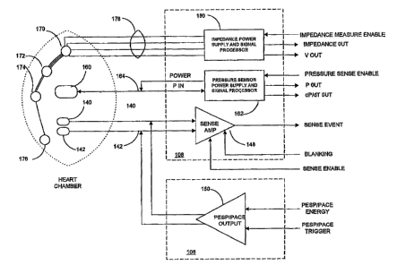
FIG. 3 schematically illustrates one pacing, sensing and parameter measuring
channel in relation to one heart chamber. A pair of pace/sense electrodes 140,
142 , a
pressure sensor 160, and a plurality, e.g., four, impedance measuring
electrodes 170, 172,
174, 176 are located in operative relation to the heart chamber.
The pair of pace/sense electrodes 140, 142 are located in operative relation
to the
heart chamber and coupled through lead conductors 144 and 146, respectively,
to the
inputs of a sense amplifier 148 located within the input signal processing
circuit 108. The
sense amplifier 148 is selectively enabled by the presence of a sense enable
signal that is
provided by control and timing system 102. The sense amplifier 148 is enabled
during
prescribed times when pacing is either enabled or not enabled as described
below in
reference to the measurement of the parameters of heart failure. The blanking
signal is
provided by control and timing system 102 upon delivery of a pacing or PESP
pulse or
pulse train to discoimect the sense amplifier inputs from the lead conductors
144 and 146
fox a short blanking period in a manner well known in the art. When sense
amplifier 148
is enabled and is not blanked, it senses the electrical signals of the heart,
referred to as the
EGM, in the heart chamber. The sense amplifier provides a sense event signal
signifying
the contraction of the heart chamber commencing a heart cycle based upon
characteristics
of the EGM, typically the P-wave when the heart chamber is the RA or LA and
the R-
wave, when the heart chamber is the RV or LV, in a manner well known in the
pacing art.
CA 02433359 2003-06-27
WO 02/053026 PCT/USO1/50276
22
The control and timing system responds to non-refractory sense events by
restarting an
escape interval (EI) timer timing out the EI for the heart chamber, in a
manner well known
in the pacing art.
The pair of pace/sense electrodes 140, 142 are also coupled through lead
conductors 144 and 146, respectively, to the output of a pulse generator 150.
The pulse
generator 150, within PESP/pacing delivery system 106, selectively provides a
pacing
pulse to electrodes 140, 142 in response to a PESP/PACE trigger signal
generated at the
time-out of the EI timer within control and timing system 102 in a manner well
known in
the pacing art. Or, the pulse generator 150 selectively provides a PESP pulse
or pulse
train to electrodes 140, 142 in response to a PESP/PACE trigger signal
generated at the
time-out of an ESI timer within control and timing system 102 in the manner
described in
the above-referenced '098 patent to cause the heart chamber to contract more
forcefully,
the increased force depending upon the duration of the ESI.
The pressure sensor I60 is coupled to a pressure sensor power supply and
signal
processor 162 within the input signal processing circuit 108 through a set of
lead
conductors 164 that convey power to the pressure sensor 160 and sampled blood
pressure
P signals from the pressure sensor 160 to the pressure sensor power supply and
signal
processor 162. The pressure sensor power supply and signal processor 162
samples the
blood pressure impinging upon a transducer surface of the sensor 160 located
within the
heart chamber when enabled by a pressure sense enable signal from the control
and timing
system 102. Absolute pressure P, developed pressure DP and pressure rate of
change
dP/dt sample values can be developed by the pressure sensor power supply and
signal
processor 162 or by the control and timing system 102 for storage and
processing as
described further below. The pressure sensor 160 and a pressure sensor power
supply and
signal processor 162 may take the form disclosed in commonly assigned U.S.
Patent No.
5,564,434.
The set of impedance electrodes 170, 172, 174 and 176 is coupled by a set of
conductors 178 and is formed as a lead of the type described in the above-
referenced ' 7I7
patent that is coupled to the impedance power supply and signal processor 180.
Impedance-based measurements of cardiac parameters such as stroke volume are
known in
the art as described in the above-referenced '417 patent which discloses an
impedance lead
having plural pairs of spaced surface electrodes located within the heart
chamber. The
CA 02433359 2003-06-27
WO 02/053026 PCT/USO1/50276
23
spaced apart electrodes can also be disposed along impedance leads lodged in
cardiac
vessels, e.g., the coronary sinus and great vein or attached to the epicardium
around the
heart chamber. The impedance lead may be combined with the pace/sense and/or
pressure
sensor bearing lead.
A measure of heart chamber volume V is provided by the set of impedance
electrodes 170, 172, 174 and 176 when the impedance power supply and signal
processor
180 is enabled by an impedance measure enable signal provided by control and
timing
system 102. A fixed current carrier signal is applied between the pairs of
impedance
electrodes and the voltage of the signal is modulated by the impedance through
the blood
and heart muscle which varies as distance between the impedance electrodes
varies. Thus,
the calculation of the heart chamber volume V signals from impedance
measurements
between selected pairs of impedance electrodes 170, I72, I74 and 176 occurs
during the
contraction and relaxation of the heart chamber that moves the spaced apart
electrode pairs
closer together and farther apart, respectively, due to the heart wall
movement or the tidal
flow of blood out of and then into the heart chamber. Raw signals are
demodulated,
digitized, and processed to obtain an extrapolated impedance value. When this
value is
divided into the product of blood resistivity times the square of the distance
between the
pairs of spaced electrodes, the result is a measure of instantaneous heart
chamber volume
V within the heart chamber.
In accordance with the present invention, the IMD measures a group of
parameters
indicative of the state of heart failure employing EGM signals, measures of
absolute blood
pressure P and/or dP/dt, and measures of heart chamber volume V over one or
more
cardiac cycles. FIG. 4 sets forth the overall operating algorithm of the IMD,
and FIGS.
SA-SC, 6, 7, and 8 set forth particular parameter measurement and calculation
algorithms
selectively incorporated into the overall operating algorithm that are all
carried out in the
microcomputer based control and timing system 102. FIGS. SA-SC, 6, 7, and 8
depict the
steps of deriving the RF, MR, EES, and tau parameters indicative of the state
of heart
failure. These parameters are determined periodically throughout each day
regardless of
patient posture and activity. However, the patient may be advised by the
physician to
undertake certain activities or movements at precise times of day or to
simultaneously
initiate the determination of the parameters though use of a magnet or a
limited function
programmer that is detected by the IMD. Certain of the parameters are only
measured or
CA 02433359 2003-06-27
WO 02/053026 PCT/USO1/50276
24
certain of the parameter data are only stored when the patient heart rate is
within a normal
sinus range between programmed lower and upper heart rates and the heart
rhythm is
relatively stable. The parameter data and related data, e.g., heart rate and
patient activity
level, are date and time stamped and stored in IMD memory for retrieval
employing
conventional telemetry systems. Incremental changes in the stored data over
time provide
a measure of the degree of change in the heart failure condition of the heart.
FIG. 4 illustrates the overall IMD function from the time of implantation
(step
5400) and initial programming (steps 402) and baseline parameter measurements
(step
5404) through successive cycles of gathering parameter data in the IMD (steps
5406 -
5420), uplink telemetry transmission of the accumulated data to an external
programmer
(step 5422) for display and analysis (step 5424), leading to possible
reprogramming (step
5402) and baseline parameter measurement (step 5404) to better assess the
heart failure
state.
Each parameter may be programmed ON or OFF, and a particular event trigger fox
starting measurement of the programmed ON parameter as well as any specific
measurement criteria can be programmed in step 5402 using conventional
downlink
telemetry transmitted commands that are received in the telemetry transceiver
124 and
forwarded to the control and timing system 102.
In addition, the physician may initially program the IMD to deliver a
stimulation
therapy, e.g., periodically delivered PESP stimulation in accordance with the
above-
referenced ' 098 patent or sub-threshold anodal stimulation (AS) in accordance
with the
above-referenced '464 patent in order to enhance cardiac function after step
5402, for
example. The physician can then later reprogram the therapy based on the
accumulated
and analyzed parameter data and any indication therein that the heart failure
state is
changing or not responding to the stimulation therapy. Alternatively, the
physician can
prescribe a drug therapy and later adjust the drug therapy based upon the
accumulated and
analyzed parameter data and any indication therein that the heart failure
state is changing
or not responding to the drug therapy.
The baseline parameter measurements are optionally performed for each
programmed ON parameter by invoking the steps of FIGS. SA-SC, 6, 7, and/or 8,
uplink
telemetering the parameter data and analyzing the uplink telemetered data n
following
implant and following subsequent telemetry sessions. The initial and updated
baseline
CA 02433359 2003-06-27
WO 02/053026 PCT/USO1/50276
2S
parameter measurements can be stored in the IMD memory and/or stored
externally in a
patient file maintained by the physician with a date and time stamp and other
pertinent
data, e.g. patient activity level measured by activity signal processor
circuit 118 and
patient heart rate.
S After implant, the programmed ON parameters are measured when an event
trigger
for the specific parameter occurs and when heart rate and/or rhythm criteria
are met as set
forth in steps 5406 - 5412. The event criteria of step 5406 may be a
programmed time or
multiple times of every day or specified days of the week or month or the
detection of the
patient initiated parameter measurement or some other programmed event, e.g.,
a
combination of the time or times of day and a level of patient exercise
indicated by the
activity signal processor circuit 118.
Typically, the measurement of the listed parameters should take place when the
heart rate is in a normal range and is stable within a certain stability
tolerance which can
both be programmed by the physician and are determined over a series of heart
cycles in
1 S steps 5408 - 5412 in a manner well known in the art. The measurement of
the particular
parameter corresponding to the satisfied event criteria takes place in step
5414 if the heat
rate/stability criteria are satisfied in step 5412 or is aborted if the heart
rate/stability
criteria are not satisfied in step 5412.
The heart rate and/or stability continues to be monitored through steps s416
and
5412, and the parameter measurement that is commenced in step 5414 may also be
aborted if the heart rate and/or stability changes such that the heart
rate/stability criteria
become no longer satisfied in step 5412 before the parameter measurement steps
are
completed. The completed parameter measurement data is stored in IMD memory
with a
date and time stamp and any other pertinent information, e.g., patient
activity level, in step
5418. Steps 5406 through 5418 are repeated each time that the event trigger
criteria for a
particular parameter measurement are satisfied until the process is
interrupted by initiation
of a telemetry session by the physician and uplink telemetry transmission of
the
accumulated parameter data in step 5422. The history of the number, times and
dates of
successive parameter measurements can also be stored in IMD memory, but the
stored
parameter data and related data may be discarded on a FIFO basis if the memory
capacity
assigned to such data storage is exceeded.
CA 02433359 2003-06-27
WO 02/053026 PCT/USO1/50276
26
Collection of MR Parameter Data:
The MR parameter is believed to be a useful indicator of the state of heart
failure
and can provide an indication of the state of progression or regression of the
heart failure
through the comparison of MR parameter data collected over time.
The time constants for systolic and diastolic MR provide indirect evidence
regarding the
sarcoplasmic reticular (SR) function. Systolic restitution is dependent on the
release of
calcium from the SR and diastolic restitution is dependent on the uptake of
calcium by the
SR.
FIGS. SA-SC depict the steps of determining the MR parameter in step 5414 of
FIG. 4 in paced heart cycles to ensure steady rate and rate stability.
Alternatively, another
embodiment of this invention relies on a stable intrinsic rhythm for all but
the ESI beats or
relies entirely on intrinsic rhythms and spontaneous ectopy for an analogous
determination
of the MR parameter. Further, although this embodiment relies on pressure as a
hemodynamic variable, another embodiment relies on a parameter derived from
the
volume signal. FIGS. 5B and SC depict the steps 5510 for determining dP/dt MAX
(SS)
and dPldt MIN (SS) and/or RVDP (SS) (RVDP = RV systolic pressure - RV
diastolic
pressure) within a reference steady state (SS) paced heart cycle and 5534 for
determining
dP/dt MAX (ES) and dP/dt MIN (ES) and/or RVDP (ES) within a ESI paced heart
cycle
of FIG. 5A in greater detail. When the MR parameter measurement is entered, it
is
necessary to determine the intrinsic EI in steps 5504 and 5506. In step 5508,
a pacing EI
is calculated that is sufficiently shorter than the intrinsic EI to overdrive
pace the heart
chamber, and the initial, shortest, ESI is calculated as a fraction of the
pacing EI or is
determined during the initial baseline programming and measuring steps 5402
and 5404.
The ESI is generally chosen to be as short as possible but to exceed the
refractory period
of the heart chamber that takes place as the cardiac cells repolarize
following a preceding
pacing pulse.
The ESI is incremented in step 5554, and steps 5510 shown in FIG. 5B and 5534
shown in FIG. SC are repeated to derive a series of sets of dP/dt MAX (SS) and
dP/dt MIN
(SS) and/or RVDP (SS) values and dP/dt MAX (ES) and dP/dt MIN (ES) and/or RVDP
(ES) values until the ESI becomes close in length to the pacing EI as
determined in step
5556. Each repetition of steps 5510 through 5552 is separated by a rest
interval, e.g., 15
CA 02433359 2003-06-27
WO 02/053026 PCT/USO1/50276
27
seconds, as determined in steps 5558 and 5560 to allow the mechanical heart
function to
stabilize.
The determination of dP/dt MAX (SS) and dP/dt MIN (SS) of step 5510 is made
within a reference paced heart cycle of a series "M" of paced heart cycles.
For example,
M = 8, in FIG. 5B, and the determination of dP/dt MAX (SS) and dP/dt MIN (SS)
of step
5510 is made in the 6th heart cycle as set forth in steps 5512 through 5526 of
FIG. 5B.
The pacing EI determined in step 5508 is timed out, and a pacing pulse is
delivered at its
time-out in steps 5514 - 5516. A pace pulse count is incremented in step 5518.
The
current pace pulse count is examined in steps 5520, 5522, and 5524, and steps
5512 -
5524 are repeated until the pace pulse count equals 6, whereupon the pressure
sensor
power supply and signal processor 162 is enabled in step 5526 to provide the
sampled
blood pressure P, and dP/dt values throughout the 6th heart cycle.
Alternatively, if the
' pressure sensor power supply and signal processor 162 are always enabled,
then the
sampled blood pressure P, and dP/dt values output in the 6th heart cycle are
used.
The pressure sensor power supply and signal processor 162 is no longer enabled
to
provide the sampled blood pressure P and dP/dt values or the outputted blood
pressure P,
and dP/dt values are not used in step 5528 when the pace pulse count equals 7
as
determined in step 5522. The RVDP, dP/dt MAX (SS) and dP/dt MIN (SS) values
are
determined in step 5530 and temporarily stored in step 5532.
The determination of dP/dt MAX (ES) and dPldt MIN (ES) of step 5534 after the
8th heart cycle is set forth in steps 5536 through 5552 of FIG. SC. The
initial ESI
calculated in step 5508 or the incremented ESI calculated in step 5556 of FIG.
5A is timed
out in steps 5536 and 5538. The ES pulse is delivered in step 5540, and the
pressure
sensor power supply and signal processor 162 is enabled to measure the heart
chamber
~ blood pressure and provide the P and dP/dt signals to control and timing
system 102. The
sampled blood pressure P and dP/dt signals are collected in step 5542 over the
pacing EI
that is timed out in steps 5544, 5546 and 5548. Then, the RVDP, dP/dt MAX (ES)
and
dP/dt MIN (ES) values are determined in step 5530 and temporarily stored in
step 5552.
Then, the MR parameter value tc~.G for the initial or incremented current ESI
is
determined and stored in IMD memory in step 5562. First, each of the dP/dt MAX
(ES)
values determined in step 5550 for each cycle is normalized with respect to
the P/dt MAX
(SS) determined in step 5530, and each of the dP/dt MIN (ES) values determined
in step
CA 02433359 2003-06-27
WO 02/053026 PCT/USO1/50276
28
5550 for each cycle is normalized to the dP/dt MIN (SS) determined in step
5530. For the
systolic function, normalizing is effected by dividing dP/dt MAX (ES) by dP/dt
MAX
(SS) and multiplying the result by 100.
For the diasystolic function, normalizing is effected by dividing dP/dt MIN
(ES) by dP/dt
MIN (SS) and multiplying the result by 100. Systolic pulse pressure P and/or
developed
pressure DP can be normalized iii the same manner, if the SS and ES values are
also
collected in steps 5532 and 5550.
Then, steps 5510 through 5554 are then performed using the initial ESI to
determine the initial MR value tcmrc. FIG. 14 graphically illustrates the
tcmrc of the
normalized dP/dt MAX (ES) determined in step 5562 in FIG. 54. After
calculating all the
normalized values for systolic and diastolic function, the diastolic and
systolic time
constants (tcmrc) are determined in step 5562 using the following equations:
Mechanical Restitution:
RVDP or dP/dt MAX = CRmax * {1-exp[(ESIO - ESI)/tcrrnc]};
1 S or when plotted as shown in FIG. 14:
Y = CRmax * {1-exp[(ESIO - X)/tcmrc]}
Where:
RVDP or dP/dt MAX is the normalized value
CRmax is the maximal (plateau) of the contractile response
ESIO is the smallest ESI that produces a mechanical response ("initial ESI")
tcmrc is the time constant of mechanical restitution
Relaxation Restitution:
Eaxly phase including data up to the "basic cycle length" (paced rate):
Rn = (KO - K~ * {exp[(ESIO - ESI)/tcRl ]} + Ka
or when plotted as shown in FIG. 14:
Y = (KO - Ka) * {exp[(ESIO - X)/tcRl]} + Ka
Where:
Rn is the normalized relaxation parameter (dP/dtmin 1)
ESIO is the smallest ESI that produces a mechanical response ("initial ESI")
KO is an estimate of Rn at ESIO
CA 02433359 2003-06-27
WO 02/053026 PCT/USO1/50276
29
Ka is the plateau asymptote (of the response) during the first phase of
diastolic restitution
tcRl is the time constant of the first phase of diastolic restitution
Late phase:
Rn = Kb =~ {1-exp[(ESIO - ESI)/tc~]]
or when plotted as shown in FIG. 14:
Y = Kb ~ f 1-exp[(ESIO - X)/tcg~ ])
Where:
Rn is the normalized relaxation parameter (dP/dtm~ 1)
ESIO is the smallest ESI that produces a mechanical response ("initial ESI")
Kb is the plateau asymptote (of the response) during the late phase of
diastolic restitution
tc~ is the time constant of the second phase of diastolic restitution
Collection of RF Parameter Data:
The recirculation fraction RF parameter is believed to be a useful indicator
of the
state of heart failure and can provide an indication of the state of
progression or regression
of the heart failure through the comparison of RF parameter data collected
over time. The
recirculation fraction in patient's with normal left ventricular function
(contxol) and with
left ventricular function impaired by dilated cardiomyopathy (COCM) is
illustrated in
FIG. 9 from Seed, Noble et al., "Relationships Between the Beat-to-Beat
Interval and the
Strength of Contraction in the Healthy and Diseased Human Heart", CIRCULATION
70:799-805, 1984.
The primary information necessary to compute the RF parameter is the
measurement of cardiac contractile performance ovex a consecutive series of
cardiac
cycles immediately following a cardiac cycle in which a premature intrinsic
beat or
extrasystole is sensed or immediately following one or more cardiac cycles
that an ES
pace pulse is delivered at a predetermined ESI. In the preferred embodiment,
an
electrogram signal (R-wave) is used to define cardiac cycle boundaries and
measure
intrinsic R-R intervals. Although it is possible to derive cardiac cycle
boundaries from
mechanical parameters such as ventricular pressure, these parameters are less
reliable for
premature beats that do not develop much mechanical response.
CA 02433359 2003-06-27
WO 02/053026 PCT/USO1/50276
In addition, an index of the strength of contraction of the heart chamber is
measured over a series of succeeding heart cycles to provide a strength of
contraction
value. The RF parameter of the heart chamber is derived from the accumulated
series of
strength of contraction values representing the mechanical response of the
heart chamber
5 to the electrical stimuli applied to the heart chamber prematurely at
expiration of the
extxasystolic escape interval. The index can be determined by a number of
sensed
parameters including blood pressure, chamber volume or a geometry change of
the
chamber or by the acceleration of the contraction of the chamber through use
of an
accelerometer. In a preferred embodiment , a continuous RV pressure signal is
processed
10 to reveal the maximum dP/dt (dP/dt MAX) over each cardiac cycle. The RVDP
or RV
systolic pressure alone could alternatively be used. An alternative embodiment
relies on
an analogous parameter derived from the volume V signal such as dV/dt MAX.
FIG. 6 depicts the steps of determining the RF parameter in step 5414 of FIG.
4.
During these pressure measurements, the intrinsic heart rate is determined,
and the heart is
15 paced at a pacing rate just above the intrinsic heart rate in order to
rigorously control for
rate (force-interval) and Frank-Starling filling time (length-tension)-
effects. It should be
noted that it is desirable to avoid pacing, in part or completely if a normal
heart rate and
stable rhythm exists to help reduce any extra arrhythmia risk associated with
the pacing. It
should also be noted that pacing can be altogether eliminated by relying upon
intrinsic
20 premature beats or extrasystoles. An IMD that is programmed to continuously
monitor the
electrogram and pressure signals can wait until the heart rate is stable and
regular to make
the RF parameter assessment and can afford to discard RF parameter assessments
that are
made over a series of heart beats where the heart rate or rhythm deteriorates
or the
extrasystole is not timed well. However, since it is the more complex process,
FIG. 6
25 depicts the RF parameter measurement taking place during fixed rate pacing.
When the RF parameter measurement process is entered, it is necessary to
determine the intrinsic EI in steps S604 and 5606. In step 5608, a pacing EI
is calculated
that is sufficiently shorter than the intrinsic EI to overdrive pace the heart
chamber, and an
ESI is calculated as a fraction of the pacing EI or is determined during the
initial baseline
30 programming and measuring steps 5402 and 5404. The ESI is generally chosen
to be as
short as possible but to exceed the refractory period of the heart chamber
that takes place
as the cardiac cells repolarize following a preceding pacing pulse to ensure
that the heart
CA 02433359 2003-06-27
WO 02/053026 PCT/USO1/50276
31
will respond and depolarize. Alternatively, the T-wave repolarization waveform
of the
EGM can be sensed, and the ESI determined as a function of the Q-T interval
for this or
any of the other sensor signal parameters that depend on an ESI.
Then, the IMD enters a fixed rate pacing mode in step 5610 successively
delivering "M" pacing pulses at the time-out of the EI to stabilize the heart
rate and
mechanical pumping function of the heart. The pressure sensor power supply and
signal
processor 162 is subsequently enabled to measure the heart chamber blood
pressure and
provide the P and dP/dt signals to control and timing system 102. A reference
dP/dt MAX
value is measured during one of the fixed rate pacing cycles or several dP/dt
MAX values
are measured and averaged to provide the reference dP/dt MAX value in step
5612. If a
sense event occurs during the fixed rate pacing cycles, the RF parameter
measurement is
aborted.
For simplicity, these steps 5602 - 5612 can be the same as steps 5502 - 5532
of
FIGs. 5A and SB, where M=8, for example. In addition, the determination of the
MR
parameter and the RF parameter can be made simultaneously.
An ES pulse or pulse train is then delivered in steps 5614 through 5618 in the
next
paced heart cycle. AlteW atively, a series of such ES pulses or pulse trains
can be
delivered in a like series of paced heart cycles by repeating steps 5614 -
5618 a number of
times, e.g., three times. In either case, the pressure sensor power supply and
signal
processor 162 is enabled to measure the heart chamber blood pressure and
provide the P
and dP/dt signals to control and timing system 102. The RF dP/dt MAX values
are then
determined and temporarily stored over "K" succeeding heart cycles in steps
5620 - 5634
in order to derive the RF time constant in step 5636. The RF parameter
measurement is
terminated if an extrasystole occurs and is sensed in step 5626.
Alternatively, when fixed rate pacing is not employed, sense events are
detected
and mark the end of a preceding heart cycle and the beginning of the next
heart cycle. The
intrinsic heart rate and rhytlun are examined to ensure that they are
relatively stable, and
the RF measurement is aborted if the intrinsic heart rate and rhytlun alters
significantly
enough to distort the measurement.
An EI count is incremented in step 5632, and the measurement of the RF dP/dt
MAX values over the remaining heart cycles is repeated in steps 5620 - 5630
until "K"
heart cycles are counted. The RF time constant is determined in step 5636 and
stored with
CA 02433359 2003-06-27
WO 02/053026 PCT/USO1/50276
32
the date and time stannp and any other useful related data after the EI count
reaches
"I~M~ ", as determined in step 5634.
It should be noted that at least the initial dP/dt MAX values following the
delivery
of the ES stimulation should be larger than the dP/dt MA.X (SS) determined in
step 5612.
The determination of the RF time constant in step 5636 may be aborted if the
dP/dt MAX
(SS) determined in step 5612 is greater than at least the first post ES
stimulation P/dt
MAX value.
The determination of RF is made from the decay of the I~ dP/dt MAX amplitudes
from dP/dt MAXk_1. The following explanation is made with xespect to FIGs. 10-
12.
Notation:
time, t
cardiac cycle, k
R-R interval, RRk
Baseline R-R interval, RRO
Premature (extrasystolic) R-R interval, ESI
RV dP/dt MAX, dP/dth
Baseline RV dP/dt MAX. dP/dt0
Steps:
Wait for (or pace) a series of suitable R-R intervals
Note RRO and corresponding dP/dt0
Confirm RR stable and in a normal range
Pace the atrium or ventricle at the time-out of the ESI to produce one or more
premature ventricular beats (extrasystoles) not long after the end of the
preceding cycle's
refractory period or T wave.
Conftrm ESI c RRO
Return to the (paced) R-R intervals of the first step for subsequent beats k =
1,
Kmax
Record RRk and dP/dtk
If RRk are approximately equal to RRO and if dP/dtl > dP/dt2 > dP/dtp
CA 02433359 2003-06-27
WO 02/053026 PCT/USO1/50276
33
Compute RF from the slope of the dP/dtk+1 versus dP/dtk data series where k
= 1, Kmax
FIGS. 10 and 11 illustrate signals from an animal study including the measured
ventricular EGM (Vegm), pulmonary flow, right ventricular blood pressure
(RVP), and
RV dP/dt. The heart rate is regular and stable in the heart cycles preceding
the delivery of
three paced extrasystoles marked by the three vertical lines. Three pacing
energy ES
pulses are delivered in the right ventricle after an ESI timed from the
detected R-wave and
just following the end of the QT interval, resulting in increased contractile
performance of
the RV which subsequently decays over K heart cycles starting at k=1. FIG. 12
also
graphically illustrates the exponential decay of RV dP/dt MAX over the K
cardiac cycles
following the applied three ES pulses. The RF parameter is derived from the
decay in the
dP/dt MAX values over cardiac cycles k=1, 2, 3, . . .K counted from the last
applied ES
pulse. The dP/dt MAX values and their cardiac cycle indices
k=l, 2, 3, . . .K, are stored in IMD memory for determination of the RF
parameter as
described above.
FIG. 13 graphically illustrates the determination of the RF parameter from the
decay of the dP/dt MAX values over cardiac cycles k=1, 2, 3, . . .K. The slope
of the line
determined by linear regression is RF = 0.725. Roughly 75% of the potentiation
manifest
on a previous beat is evident on the current beat. Steady state or reference
RV dP/dt MAX
is approximately 320 mm Hg/s in this example from an anesthetized normal dog.
If desired, it is possible to convert from RF to beat or time constant where:
Beat constant = -[ln(RF)]-1, (the number of cycles needed for potentiated
dP/dt to decay to
1/e).
Time constant = -RRO / ln(RF), (the time needed for potentiated dP/dt MAX to
decay to
1/e).
For this example, the beat constant is 3.1 beats and time constant is 1.6
seconds.
Collection of Tau Parameter Data:
The ventricular relaxation time constant or tau (t ) parameter is believed to
be a
useful indicator of the state of heart failure and can provide an indication
of the state of
progression or regression of the heart failure through the comparison of tau
parameter data
collected over time. The primary information necessary to compute a time
constant of
CA 02433359 2003-06-27
WO 02/053026 PCT/USO1/50276
34
relaxation or tau is the drop in ventricular pressure at the end of systole
and in the first part
of diastole. In the preferred embodiment, an EGM signal, e.g., the R-wave, is
used to
define cardiac cycle boundaries and to measure R-R intervals, and a continuous
pressure P
signal, e.g.., RVP, is processed to reveal tau for each cardiac cycle where it
is measured.
Alternatively, a relaxation time constant may also be determined from an
analogous
computation with the volume signal.
The basic computational algorithm is described below in reference to FIGS. 4
and 8
employing the notation:
time, t
cardiac heart cycle, k
R-R interval, RRk
Baseline R-R interval, RRp
Ventricular pressure, P(t)
Maximum ventricular pressure, Pmax
Time of occurrence of Pm~, Tpnlax
Relaxation time constant, tauk
Time of occurrence of dP/dtmin~ TdPdtmin
The tau parameter is periodically measured from time to time to collect a data
set
stored in IMD memory along with time and date stamp and other patient data of
interest to
determine if the tau parameter is relatively unchanged or has changed from an
earlier
uplink telemetered set of such data. It is desirable that the RRk interval of
each measured
tau parameter of the stored data set is comparable so that the tau parameter
is not distorted
by heart rate variability. The tau parameter measurement can be made in a
single heart
cycle "k" where the current RRk is not significantly different than a baseline
interval,
RRp, determined in one or more preceding heart cycles k_1 , k-2 , et seq. In
this case, the
determined tau parameter and the intrinsic RRO and RRk may all be date and
time
stamped and stored in IMD memory with other relevant patient data, so the
stored tau
parameter values can be correlated with the RRO and RRk.
However, the heart can be paced at a rate just above the intrinsic EI to
provide a
paced RRk in order to rigorously control for rate (force-interval) and Frank-
Starling filliilg
CA 02433359 2003-06-27
WO 02/053026 PCT/USO1/50276
time (length-tension) effects during this measurement. Or, the heart could be
paced at a
programmed, relatively high, pacing rate to provide a series of paced baseline
RRO
followed by a paced RRk unless the intrinsic heart rate exceeds the programmed
paced
heart rate. When all conditions are met the determined tau parameter and the
paced RRO
5 and RRk may all be date and time stamped and stored in IMD memory with other
relevant
patient data, so the stored tau parameter values can be correlated with the
RRO and RRk.
FIG. 8 illustrates the blood pressure measurements taking place during an
intrinsic
RRk that is within RRO bounds in steps 5806 - 5814 or a paced RRk that is not
interrupted by a early or extrasystolic sense event in steps 5822 - 5836. If
the conditions
10 are satisfied, then the determination of tau takes place in steps 5816 and
5818. At the
outset, steps 5408 through 5410 of FIG. 4 must be satisfied for k_1,
k-2 , etc., heart cycles to determine a baseline intrinsic RRO. in Step 5802,
and the
determination is made in step 5804 whether the tau is to be determined during
an intrinsic
or paced RRk. This determination may be based on a programmed preference that
is
I S always followed or the IMD may be programmed to preferentially follow the
steps 5806 -
5814 but to revert to steps 5822 - 5836 if step 5814 is not satisfied one or
more times
Assuming that the tau parameter is measured during an intrinsic RRk as
determined in step 5804, the RRk interval is started on the next sense event
detected in
step 5806 would typically be the RV R-wave, but the on set of RV dP/dt and a
threshold
20 criterion could be employed instead. Upon detection of a sense event in
step 5806, the
pressure sensor power supply and signal processor 162 is enabled to measure
the heart
chamber blood pressure and provide blood pressure signals to control and
timing system
102. The blood pressure in the heart chamber, e.g., the RV, is sampled in step
5808 while
the intrinsic RRk times out between the beginning and ending sense event to
derive the
25 "N" sampled and digitized pressure values, e.g., N RVP and N RV dP/dt
digitized
samples. The intrinsic RRk is measured in step 5812 after the ending sense
event is
detected in step 5810, and the measured intrinsic RRk is compared to the
reference RRO in
step 5814 to determine if the difference is within defined bounds for rate and
rate stability.
The N RVP and N RV dP/dt digitized samples are discarded if the intrinsic
heart rate and
CA 02433359 2003-06-27
WO 02/053026 PCT/USO1/50276
36
rhythm of the current intrinsic RRk varies significantly enough to make the
tau
measurement of steps 5816 and 5818 atypical.
Steps 5822 - 5836 are followed if the paced mode is determined in step 5804,
and
if pacing rate that is employed would overdrive the intrinsic heart rate
reflected by the
intrinsic baseline RRO determined in step 5802. In this illustrated
embodiment, the paced
RRk is determined from the intrinsic baseline RRO in step 5822 as a pacing EI.
The
pacing EI is timed out after the next sense event in steps 5826 and 5828, and
a first pacing
pulse is delivered in step 5830 commencing the paced RRk. As noted above, a
paced
baseline RRO could first be developed over a number of paced heart cycles
using the
determined pacing EI. In addition, the pacing EI could be programmed to
overdrive the
patient's typical intrinsic heart rate.
The pressure sensor power supply and signal processor 162 is enabled in step
5832
to measure the heart chamber blood pressure and provide blood pressure signals
to control
and timing system 102. The blood pressure in the heart chamber, e.g., the RV,
is sampled
in step 5832 while the intrinsic RRk times out from the pacing pulse to derive
the "N"
sampled and digitized pressure values, e.g., N RVP and N RV dPldt digitized
samples.
The RVP and RV dP/dt digitized samples derived in step 5832 are discarded if a
sense event occurs in step 5834 before the pacing EI times out as determined
in step 5836.
In this case, the tau measurement would be aborted or restarted back at step
5802.
If the intrinsic or paced RRk are acceptable, then the N RVP and N RV dP/dt
digitized samples derived in step 5808 or 5832 are subjected to one of the
following
algorithms to determine the sample time that dP/dt MIN sample was derived in
step 5816.
this is accomplished by looking for the time corresponding to a minimum of the
dP/dt
signal or for the pressure to have declined to a specific fraction of its
maximum for this
cardiac cycle. Denote this time, ak, which is constrained a > Tp max and
calculate it by:
or
Then tau, , is computed in step 5818 from a suitably low pass filtered version
of P and
dP/dt by:
for , or
respectively.
CA 02433359 2003-06-27
WO 02/053026 PCT/USO1/50276
37
This estimate of tau is used in subsequent data logging, diagnostic, or
therapeutic steps
only if it is in a suitable range. The calculated tau value is date and time
stamped and
stored in IMD memory with other related patient data of interest.
Computation of relaxation time constant tau from an RV pressure signal is also
illustrated in the waveforms of FIGs. 15-17. FIG. 15 illustrates the
computation of the
relaxation time constant tau from the RV pressure signals during an animal
study. The
exponential decay portion of RVP begins from the time of RV dP/dt MIN at about
5.92
seconds. In this example derived from the instantaneous ratio of P to dP/dt
(bottom
panel), RV tau is computed to be about 68 ms.
FIGS. 16 and 17 Illustrate the concordance of RV tau and LV tau during an
animal
study wherein both the RV and LV were instrumented to derive LV pressure
(LVP), RV
pressure (RVP), LV dP/dt and RV dP/dt. FIG. 16 illustrates baseline
conditions, and FIG.
17 illustrates conditions after about 90 seconds intravenous infusion of
isoproterenol 0.02
ug/kg/min. Contractility, as evidenced by RV and LV dP/dt in FIG. 17, is
enhanced by
isoproterenol (LV dPldt mar increased from 1200 to 1440 mm Hg/s). Relaxation
is also
significantly shortened as seen in both RV tau and LV tau, falling from 32 ms
and 31 ms
in FIG. 16 to 2I ms and 23 ms respectively, in FIG. 17. But, in both cases, it
can be seen
that the RV tau closely tracks the LV tau, and that it is feasible to employ
RVP and RVP
dP/dt to derive an RV tau that is representative of the LV tau, thereby making
it safer and
simpler to implant the pressure sensor.
It should also be noted that the time constant of ventricular contraction can
be
determined using an analogous procedure. For example, over a time window
immediately
preceding dP/dt MAX, the ratio of P to dP/dt can be averaged to yield the time
constant of
exponential growth of pressure in the isovolumic period. This is an index of
systolic
function.
Collection of End Systolic Elastance Parameter Data:
The end systolic elastance EES parameter is believed to be a useful indicator
of the
state of heart failure and can provide an indication of the state of
progression or regression
of the heart failure through the comparison of EES parameter data collected
over time.
The end systolic elastance EES parameter comprises a slope determined from a
collection
CA 02433359 2003-06-27
WO 02/053026 PCT/USO1/50276
38
or "cloud" of "n" data points of end systolic PES measurements plotted against
the
simultaneously determined end systolic heart chamber volume VES measurements.
FIG. 7 depicts the steps of determining the EES parameter in step 5414 of FIG.
4.
When the EES parameter measurement is started, it can be conducted during "n"
successive paced heart cycles as illustrated in steps 5704 - 5706 or during
intrinsic heart
cycles as illustrated by the broken lines. In the latter case, it may be
advisable to make a
determination that the heart rate and rhythm remain within prescribed ranges
between
steps 5702 and 5712. In the former case, the pacing EI is calculated that is
sufficiently
shorter than the intrinsic EI to overdrive pace the heart chamber in step
5704, and fixed
rate pacing is carried out in steps 5704 - 5708 at least for "n" programmed
pacing cycles.
In either case, the pressure sensor power supply and signal processor 162 is
enabled in step 5712 to measure the heart chamber blood pressure and provide
"N"
sampled P and dP/dt signals over the heart cycle. At the same time, the
impedance power
supply and signal processor 180 is enabled in step 5714 to develop "N" volume
V signals
over the heart cycle. The "N" sampled P and dP/dt and volume V signals are
digitized in
step 5716 and applied to control and timing system 102.
The end systolic point PES and VES is determined in step 5718 and stored in
IMD
memory in step 5720. The determination of the end systolic PES and VES samples
at the
end systolic point in the heart cycle is made by first determining dP/dt MIN
sample and
selecting a P sample and V sample at a short time, e.g., 20 ms, prior to the
dP/dt MIN
sample. In this way, "n" sets of [PES , VES] data points are accumulated for
determination of EES and derivation of a correlation coefficient R and squared
correlation
coefficient R2 in step 5726.
The EES data set count is then incremented in step 5722, and the incremented
count is compared to a programmed data set count "n" in step 5724. The process
of
determining the n end systolic point PES and VES values is commenced again for
the next
intrinsic EI'at step 5702 or the next paced EI at step 5704, and the process
is repeated until
the programmed data set count "n" is reached.
It should also be noted that the event trigger criteria of step 5406 can be
programmed in step 5402 to be "all times" that step 5412 is met or fixed rate
pacing is
CA 02433359 2003-06-27
WO 02/053026 PCT/USO1/50276
39
provided in steps 5704 - 5708. In this case, "n" sets of [PES , VES] data
points are
continuously accumulated on a FIFO basis for determination of EES and
derivation of a
correlation coefficient R and squared correlation coefficient R2 in step 5726.
In this
variation, steps 5722 and 5724 are always satisfied when the first "n" sets of
[PES , VES]
data points are accumulated.
Then, in either case, in step 5726, a linear regression of the "n" sets of
~'ES ~ VES] data points is conducted using standard linear regression
techniques to derive
the slope of the sampled data set, EES, a correlation coefficient R and the
squared
correlation coefficient R2 as depicted in FIGS. 19 and 21 as described further
below.
In step 5728, the squared correlation coefficient R2 of the "n" sets of [PES ,
VES]
data points data set (the sample squared correlation coefficient R2) is
compared to a
threshold squared correlation coefficient R2 (e.g. 08 - 0.9) that is initially
programmed in
step 5402.
The slope of the sampled data set of "n" end systolic [PES : VES] data points
determined in step 5726 is saved as the EES in step 5730 if the sample squared
correlation
coefficient R2 exceeds the threshold squared correlation coefficient R2 value
as
determined in step 5728. If the threshold condition is not met, then a slope
of the sampled
set of "n" end systolic [PES , VES] values cannot be meaningfully determined.
The
accumulated data set is either discarded and the EES parameter measurement
aborted as
shown in FIG. 7 or the data set is updated on a FIFO basis by starting again
at either step
5702 or step 5706. The accumulated data set and/or slope EES is then saved
with other
associated data in IMD memory in step 5730 if the slope can be determined from
the
clustered plotted intersecting data points of "n" end systolic [PES , VES]
values.
FIG. 18 is a plot of ten consecutive PV loops during a modification of preload
(vena caval partial occlusion) with end systolic PV points shown at the upper
left of FIG.
18. When a linear regression is performed using these ten end systolic PV
points of FIG.
18, a straight line is formed as shown in FIG. 19. The fit of the line shown
in FIG. 19 to
the points is very good with correlation R2 = 0.998. An end systolic elastance
EES of
CA 02433359 2003-06-27
WO 02/053026 PCT/USO1/50276
9.69 is evidenced by the slope of the line. It is expected that the slope will
change in a
manner that signifies the progression or remission of heart failure in a
patient's heart.
By contrast, FIG. 20 is a plot of ten consecutive PV loops at a baseline
condition of
a relatively normal heart evidencing little physiologic change in the measured
P and V.
As ~a result, the tan end systolic PV points are on top of each other in the
upper left corner
of FIG. 20. When a linear regression is performed using these ten end systolic
PV points
in FIG. 21, these points do not reliably form a good straight line and thus do
not permit an
estimation of EES. The correlation of R2=0.322 is sufficient to recognize that
the EES
slope of 3.31 is not an accurate reflection of the physiology and would be
discarded
10 following the comparison step 5726.
The end systolic elastance EES is computed periodically or continuously in
this
manner to store a set of such slopes. The stored slopes are retrieved by
uplink telemetry to
an external programmer and are subjected to linear regression analysis to
determine if a
more recent slope has changed from an earlier slope in a manner that signifies
a
15 deterioration or improvement in CHF. A decrease in EES implies a decrease
in systolic
function and loss in contractile strength.
Therapy Delivery:
Turning to FIG. 23, the timing diagram illustrates the timing of delivery of
stimulation to a heart chamber by the PESP/PACE output pulse generator 150 of
FIG. 3 in
20 relation to a timed interval from a sensed or paced event as well as
alternative pulse
waveforms of the ES stimulation. In accordance with one aspect of the pxesent
invention,
a therapeutic stimulation delay illustrated in tracing (e) is timed out from a
sensed or paced
event (e.g., the illustrated V-EVENTS) that is shorter than the refractory
period of the heart
persisting from the sensed or paced event. A stimulus pulse train is delivered
to the atria
25 and/or ventricles in the depicted therapy delivery interval of tracing (f)
commencing after
time-out of the delay so that at least the initial pulses) of the pulse train
fall within the
end portion of the refractory period. The pulses of the PESP portion of the
delivered
therapies are intended to be supra-threshold in nature, that is, of sufficient
energy to
depolarize the heart when they are delivered in the non-refractory period of
the heart cycle
30 so that the heart is captured by at least one of the PESP pulses falling
outside the
refractory period. The initial pulses delivered during the refractory period
can also
CA 02433359 2003-06-27
WO 02/053026 PCT/USO1/50276
41
potentiate the heart. For simplicity of illustration, the tracings (f) - (j)
are expanded in
length, and the depolarization of the heaxt that they cause is not depicted in
tracing (a).
The amplitude and number of refractory interval pulses and PESP pulses in each
therapy
pulse train and the spacing between the pulses may also differ from the
illustrated tracings
(g) - ~)~
The ventricular sense or pace event detected in tracing (b) also triggers the
timing
out of an escape interval in tracing (c) which may be terminated by the
sensing of a
subsequent atrial or ventricular event, depending on the operating mode of the
system.
The first depicted sequence in FIG. 23 shows the full time-out of the escape
interval in
tracing (c), the refractory period in tracing (d), and the therapy delay and
delivery intervals
in tracings (e) and (f). The therapy delay and therapy delivery intervals can
be derived as
a function of an intrinsic V-V or V-A escape interval derived by measuring and
averaging
intervals between intrinsic ventricular and/or atrial sense events or paced
events. The
therapy delay can also be determined from a measurement of the QT interval. As
illustrated, the therapy delay in tracing (e) delays delivery of the therapy
pulse train until
the QRS complex ends or about 40 - 60 ms after the V-EVENT well before the
start of the
vulnerable period of the heart which occurs near the end of the T-wave. The
therapy
delivery interval is timed to time-out well before the end of the previously
derived V-V or
V-A escape interval, but is extended fox ease of illustration of the pulse
trains in tracings
(f) - ~)_
The therapy stimulation energy is delivered in the form of a burst of X
constant or
variable energy stimulation pulses separated by a pulse separation interval
between each
pulse of the burst. All of the pulses can have the same amplitude and energy
as shown in
waveform 3 of tracing (r). Or the leading and/or trailing pulses of the pulse
train can have
ramped amplitudes similar to the waveforms 1 and 2 illustrated in tracings (g)
and (h). In
tracings (g) and (h), the ramp up leading edge amplitudes of a sub-set of the
pulses of the
burst are shown increasing from an initial amplitude to a maximum amplitude.
In tracing
(g), the ramp down trailing edge amplitudes of a further sub-set of the pulses
of the burst
are shown decreasing from the maximum amplitude to a terminating amplitude.
Alternatively, the initial set of pulses delivered during the refractory
period can
have a higher pulse amplitude or width as shown by waveform 4 illustrated in
tracing (j).
The high energy pulses delivered during the refractory period can enhance the
PESP effect
CA 02433359 2003-06-27
WO 02/053026 PCT/USO1/50276
42
during subsequent heart cycles. Tracing (j) also illustrates alternative
numbers and
spacing of the pulses of the pulse train, and it will be understood that this
embodiment can
also employ the number of pulses and pulse spacing of waveforms 1 - 3.
In addition, it may be desirable to avoid delivering any therapy pulses in the
vulnerable period of the heart near the end of the T-wave, particularly if
high energy
pulses are delivered during the refractory period. Tracing (j) also
illustrates a vulnerable
period delay between the high energy pulses delivered during the refractory
period and the
lower energy PESP pulses to avoid delivering any pulses during the vulnerable
period of
the heart. It would also be possible to Iower the pulse energy of the pulses
delivered later
in the refractory period.
The therapy delivery capability is preferably implemented into a system that
may
include conventional pacing therapies and operating modes as well as
cardioversion/defibrillation capabilities or as a stand alone system for
simply providing
pulse therapies to effect potentiation of myocardial cells between sensed
PQRST
complexes shown in FIG. 23.
Conclusion:
The above-described methods and apparatus are believed to be of particular
benefit
for patient's suffering heart failure including chronic CHF and its variants
as described
above. It will understood that the present invention offers the possibility of
monitoring
and treatment of a wide variety of acute and chronic cardiac dysfunctions
arising from:
The above described methods and apparatus are believed to be of particular
benefit
for patients suffering from heart failure including chronic HF and its
variants as described
above. It should be understood ... a wide variety of acute and chronic cardiac
mechanical
dysfunctions arising from:
Acute and chronic heart failure;
Cardiogenic shock;
Drug overdoses including agents conunonly used to treat HF such as beta
blockers;
Protracted tachyarrhythmias (e.g. VT, AT/AF) or bradycardia;
Electromechanical dissociation;
Cardiac dysfunction or pulse-less electrical activity associated with
resuscitation;
Post cardiac bypass surgery with cardioplegia;
Severe respiratory dysfunction and hypoxia;
CA 02433359 2003-06-27
WO 02/053026 PCT/USO1/50276
43
Coronary artery ischemia from thrombus or surgical manipulation;
Acute myocardial infarction; and
Any other cardiac dysfunctions and disease processes that will be apparent to
the clinician.
Consequently, the expression "heart failure" as used in above and in the
following
claims shall be understood to embrace the same.
All patents and other publications identified above are incorporated herein by
reference.
While the present invention has been illustrated and described with
particularity in
terms of preferred embodiments, it should be understood that no limitation of
the scope of
the invention is intended thereby. The scope of the invention is defined only
by the claims
appended hereto. It should also be understood that variations of the
particular
embodiments described herein incorporating the principles of the present
invention will
occur to those of ordinary skill in the art and yet be within the scope of the
appended
claims.