Note: Descriptions are shown in the official language in which they were submitted.
CA 02433416 2003-06-27
WO 03/053259 PCT/USO1/49686
A TISSUE ABLATION APPARATUS WITH A SLIDING ABLATION
INSTRUMENT AND METHOD
BACKGROUND OF THE INVENTION
1. Field of Invention
The present invention relates, generally, to ablation instrument systems that
use
ablative energy to ablate internal bodily tissues. More particularly, the
present
invention relates to preformed guide apparatus which cooperate with energy
delivery
arrangements to direct the ablative energy in selected directions along the
guide
apparatus.
2. Description of the Prior Art
It is well docmnented that atrial fibrillation, either alone or as a
consequence of other
cardiac disease, continues to persist as the most common cardiac arrhythmia.
According to recent estimates, more than two million people in the U.S. suffer
from
this common arrhythmia, roughly 0.15% to 1.0% of the population. Moreover, the
prevalence of this cardiac disease increases with age, affecting nearly 8% to
17% of
those over 60 years of age.
Atrial arrhythmia rnay be treated using several methods. Pharmacological
treatment
of atrial fibrillation, for example, is initially the preferred approach,
first to maintain
normal sinus rhythm, or secondly to decrease the ventricular xesponse rate.
Other
forms of treatment include drug therapies, electrical cardioversion, and RF
catheter
-1-
CA 02433416 2003-06-27
WO 03/053259 PCT/USO1/49686
ablation of selected areas determined by mapping. In the more recent past,
other
surgical procedures have been developed for atrial fibrillation, including
left atrial
isolation, transvenous catheter or cryosurgical ablation of His bundle, and
the
Corridor procedure, which have effectively eliminated irregular ventricular
rhythm.
However, these procedures have for the most part failed to restore normal
cardiac
hemodynamics, or alleviate the patient's vulnerability to thromboembolism
because
the atria are allowed to continue to fibrillate. Accordingly, a more effective
surgical
treatment was required to cure medically refractory atrial fibrillation of the
Heart.
On the basis of electrophysiologic mapping of the atria and identification of
macroreentrant circuits, a surgical approach was developed which effectively
creates
an electrical maze in the atrium (i.e., the MAZE procedure) and precludes the
ability
of the atria to fibrillate. Briefly, in the procedure commonly referred to as
the MAZE
III procedure, strategic atrial incisions are performed to prevent atrial
reentry circuits
and allow sinus impulses to activate the entire atrial myocardium, thereby
preserving
atrial transport function postoperatively. Since atrial fibrillation is
characterized by
the presence of multiple macroreentrant circuits that are fleeting in nature
and can
occur anywhere in the atria, it is prudent to interrupt all of the potential
pathways for
atrial macroreentrant circuits. These circuits, incidentally, have been
identified by
intraoperative mapping both experimentally and clinically in patients.
Generally, this procedure includes the excision of both atrial appendages, and
the
electrical isolation of the pulmonary veins. Further, strategically placed
atrial
incisions not only interrupt the conduction routes of the common reentrant
circuits,
but they also direct the sinus impulse from the sinoatrial node to the
atrioventricular
node along a specified route. In essence, the entire atrial myocardium, with
the
exception of the atrial appendages and the pulmonary veins, is electrically
activated
by providing for multiple blind alleys off the main conduction route between
the
sinoatrial node to the atrioventricular node. Atrial transport function is
thus preserved
postoperatively as generally set forth in the series of articles: Cox,
Schuessler,
Boineau, Canavan, Cain, Lindsay, Stone, Smith, Corr, Change, and D'Agostino,
Jr.,
The Surgical Treatment Aty-ial Fibrillation (pts. 1-4), 101 THORAC CARDIOVASC
SURG., 402-426, 569-592 (1991).
2
CA 02433416 2003-06-27
WO 03/053259 PCT/USO1/49686
While this MAZE III procedure has proven effective in ablating medically
refractory
atrial fibrillation and associated detrimental sequelae, this operational
procedure is
traumatic to the patient since this is an open-heart procedure and substantial
incisions
are introduced into the interior chambers of the Heart. Consequently, other
techniques
have been developed to interrupt atrial fibrillation restore sinus rhythm. One
such
technique is strategic ablation of the atrial tissues through ablation
catheters.
Most approved ablation catheter systems now utilize radio frequency (RF)
energy as
the ablating energy source. Accordingly, a variety of RF based catheters and
power
supplies are currently available to electrophysiologists. However, radio
frequency
energy has several limitations including the rapid dissipation of energy in
surface
tissues resulting in shallow "burns" and failure to access deeper arrhythmic
tissues.
Another limitation of RF ablation catheters is the risk of clot formation on
the energy
emitting electrodes. Such clots have an associated danger of causing
potentially lethal
strolces in the event that a clot is dislodged from the catheter. It is also
very difficult
to create continuous long lesions with RF ablation instruments.
As such, catheters which utilize other energy sources as the ablation energy
source,
for example in the microwave frequency range, are currently being developed.
Microwave frequency energy, for example, has long been recognized as an
effective
energy source for heating biological tissues and has seen use in such
hyperthermia
applications as cancer treatment and preheating of blood prior to infusions.
Accordingly, in view of the drawbacks of the traditional catheter ablation
techniques,
there has recently been a great deal of interest in using microwave energy as
an
ablation energy source. The advantage of microwave energy is that it is much
easier
to control and safer than direct current applications and it is capable of
generating
substantially larger and longer lesions than RF catheters, which greatly
simplifies the
actual ablation procedures. Such microwave ablation systems are described in
the
U.S. Patent Numbers 4,641,649 to Walinsky; 5,246,438 to Langberg; 5,405,346 to
Grundy, et al.; and 5,314,466 to Stern, et al, each of which is incorporated
herein by
reference.
3
CA 02433416 2003-06-27
WO 03/053259 PCT/USO1/49686
Most of the existing microwave ablation catheters contemplate the use of
longitudinally extending helical antenna coils that direct the electromagnetic
energy in
all radial directions that are generally perpendicular to the longitudinal
axis of the
catheter. Although such catheter designs work well for a number of
applications,
such radial output is inappropriate when the energy needs to be directed
toward the
tissue to ablate only.
Consequently, microwave ablation instruments have recently been developed
which
incozporate microwave antennas having directional reflectors. Typically, a
tapered
directional reflector is positioned peripherally around the microwave antenna
to direct
the waves toward and out of a window portion of the antenna assembly. These
ablation instruments, thus, are capable of effectively transmitting
electromagnetic
energy in a more specific direction. For example, the electromagnetic energy
may be
transmitted generally perpendicular to the longitudinal axis of the catheter
but
constrained to a selected radial region of the antenna, or directly out the
distal end of
the instrument. Typical of these designs are described in the U.S. Patent
Application
S/Ns: 09/178,066, filed October 23, 1998; and 09/333,747, filed June I4, 1999,
each
of which is incorporated herein by reference.
In these designs, the resonance frequency of the microwave antenna is
preferably
tuned assuming contact between the targeted tissue or blood and a contact
region of
the antenna assembly extending longitudinally adjacent to the antenna
longitudinal
axis. Hence, should a portion of, or substantially all of, the exposed contact
region of
the antenna not be in contact with the targeted tissue or blood during
ablation, the
resonance frequency will be adversely changed and the antenna will be untuned.
As a
result, the portion of the antenna not in contact with the targeted tissue or
blood will
radiate the electromagnetic radiation into the surrounding air. The efficiency
of the
energy delivery into the tissue will consequently decrease which in turn
causes the
penetration depth of the lesion to decrease.
This is particularly problematic when the microwave antenna is not in the
blood pool,
or when the tissue surfaces are substantially curvilinear, or when the
targeted tissue
for ablation is difficult to access, such as in the interior chambers of the
Heart. Since
4
CA 02433416 2003-06-27
WO 03/053259 PCT/USO1/49686
these antenna designs are generally relatively rigid, it is often difficult to
maneuver
substantially all of the exposed contact region of the antenna into abutting
contact
against the targeted tissue. In these instances, several ablation instruments,
having
antennas of varying length and shape, may be necessary to complete just one
series of
ablations.
SUMMARY OF THE INVENTION
Accordingly, a system for ablating a selected portion of a contact surface of
biological
tissue is provided. The systerr~ is particularly suitable to ablate cardiac
tissue, and
includes an elongated ablation sheath having a preformed shape adapted to
substantially conform a predetermined surface thereof with the contact surface
of the
tissue. The ablation sheath defines an ablation lumen extending therethrough
along an
ablation path proximate to the predetermined surface. Am elongated ablative
device
includes a flexible ablation element which cooperate with an ablative energy
source
which is sufficiently strong for tissue ablation. The ablative device is
formed and
dimensioned for longitudinal sliding receipt through the ablation lumen of the
ablation sheath for selective placement of the ablative device along the
ablation path
created by the ablation sheath. The ablation lumen and the ablative device
cooperate
to position the ablative device proximate to the ablation sheath predetermined
surface
for selective ablation of the selected portion
Accordingly, the ablation sheath in its preshaped form functions as a guide
device to
guide the ablative device along the ablation path when the predetermined
surface of
the ablation sheath properly contacts the biological tissue. Further, the
cooperation
between the ablative device and the ablation lumen, as the ablative device is
advanced
through the lumen, positions the ablative device in a proper orientation to
facilitate
ablation of the targeted tissue during the advancement. Thus, once the
ablation sheath
is stationed relative the targeted contact surface, the ablative device can be
easily
advanced along the ablation path to generate the desired tissue ablations.
In one embodiment, the ablative device is a microwave antenna assembly which
includes a flexible shield device coupled to the antenna substantially shield
a
surrounding area of the antenna from the electromagnetic field radially
generated
5
CA 02433416 2003-06-27
WO 03/053259 PCT/USO1/49686
therefrom while permitting a majority of the field to be directed generally in
a
predetermined direction toward the ablation sheath predetermined surface. The
microwave antenna assembly further includes a flexible insulator disposed
between
the shield device and the antenna. A window portion of the insulator is
defined which
enables transmission of the directed electromagnetic field in the
predetermined
direction toward the ablation sheath predetermined surface. The antenna, the
shield
device and the insulator are formed for manipulative bending thereof, as a
unit, to one
of a plurality of contact positions to generally conform the window portion to
the
ablation sheath predetermined surface as the insulator and antenna are
advanced
through the ablation lumen.
In another embodiment, to facilitate alignment of the ablative device assembly
in the
ablation lumen, the ablative device provides a l~ey device which is slideably
received
in a mating slot portion of the ablation lumen. In still another embodiment,
the
system includes a guide sheath defining a guide lumen formed and dimensioned
for
sliding receipt of the ablation sheath therethrough. The guide sheath is pre-
shaped to
facilitate positioning of the ablation sheath toward the selected portion of
the contact
surface when the ablation sheath is advanced through guide lumen.
The ablation sheath includes a bendable shape retaining member extending
longitudinally therethrough which is adapted to retain the preformed shape of
the
ablation sheath once positioned out of the guide lumen of the guide sheath.
The ablative energy is preferably provided by a microwave ablative device.
Other
suitable tissue ablation devices, however, include cryogenic, ultrasonic,
laser and
radiofrequency, to name a few.
fil another aspect of the present invention, a method for treatment of a Heart
includes
forming a penetration through a muscular wall of the Heart into an interior
chamber
thereof; and positioning a distal end of an elongated ablation sheath through
the
penetration. The ablation sheath defines an ablation lumen extending along an
ablation path therethrough. The method further includes contacting, or
bringing close
enough, a predetermined surface of the elongated ablation sheath with a first
selected
6
CA 02433416 2003-06-27
WO 03/053259 PCT/USO1/49686
portion of an interior surface of the muscular wall ; and passing a flexible
ablative
device through the ablation lumen of the ablation sheath for selective
placement of the
ablative device along the ablation path. Once these events have been
performed, the
method includes applying the ablative energy, using the ablative device and
the
ablation energy source, which is sufficiently strong to cause tissue ablation.
In one embodiment, the passing is performed by incrementally advancing the
ablative
device along a plurality of positions of the ablation path to produce a
substantially
continuous lesion. Before the positioning event, the method includes placing a
distal
end of a guide sheath through the penetration, and then positioning the distal
end of
the ablation sheath through the guide lumen of the guide sheath.
In still another embodiment, before the placing event, piercing the muscular
wall with
a piercing sheath. The piercing sheath defines a positioning passage extending
therethrough, The placing the distal end of a guide sheath is performed by
placing the
guide sheath distal end through the positioning passage of the piercing
sheath.
In yet another configuration, the positioning the distal end event includes
advancing
the ablation sheath toward the first selected portion of the interior surface
of the
muscular wall through a manipulation device extending through a second
penetration
into the Heart interior chamber independent from the first named penetration.
In another embodiment, a system for ablating tissue within a body of a patient
is
provided including an elongated rail device and an ablative device. The raidl
device
is adapted to be positioned proximate and adjacent to a. selected tissue
region to be
ablated within the body of the patient. The ablative device includes a
receiving
passage configured to slideably receive the rail device longitudinally
therethrough.
This enables the ablative device to be slideably positioned along the rail
substantially
adjacent to or in contact with the selected tissue region. The ablative
device, having
an energy delivery portion which is adapted to be coupled to an ablative
energy
source, can then be operated to ablate the selected tissue region.
7
CA 02433416 2003-06-27
WO 03/053259 PCT/USO1/49686
In this configuration, the ablative device is adapted to directionally emit
the ablative
energy from the energy delivery portion. A key assembly cooperates between the
ablative device and the rail member, thus, to properly align the directionally
emitted
ablative energy toward the tissue region to be ablated. This primarily
performed by
providing a rail device with a non-circular transverse cross-sectional
dimension. The
receiving passage of the ablative device further includes a substantially
similarly
shaped non-circular transverse cross-sectional dimension to enable sliding of
the
ablative device in a manner continuously aligning the directionally emitted
ablative
energy toward the tissue region to be ablated as the ablative device advances
along the
rail device.
BRIEF DESCRIPTION OF THE DRAWINGS
The assembly of the present invention has other obj ects and features of
advantage
which will be more readily apparent from the following description of the best
mode
of carrying out the invention and the appended claims, when taken in
conjunction with
the accompanying drawing, in which:
FIGURES 1A and 1B are fragmentary, top perspective views, partially broken-
away,
of the ablation system constructed in accordance with the present invention,
and
illustrating advancement of a bendable directional reflective microwave
antenna
assembly through an ablation lumen of a ablation sheath.
FIGURES 2A-2D is series of fragmentary, side elevation views, in partial cross-
section, of the Heart, and illustrating advancement of the ablation system of
present
invention into the left atrium for ablation of the targeted tissue.
FIGURE 3 is a fragmentaay, side elevation view, in partial cross-section, of
the Heart
showing a pattern of ablation lesions to treat atrial fibrillation.
FIGURES 4A and 4B are a series of enlarged, fragmentary, top perspective view
of a
pigtail ablation sheath of the ablation system of FIGURES 2C and 2D, and
exemplifying the ablation sheath being advanced into one of the pulmonary vein
orifices.
8
CA 02433416 2003-06-27
WO 03/053259 PCT/USO1/49686
FIGURE 5 is a front schematic view of a patient's cardiovascular system
illustrating
the positioning of a transseptal piercing sheath through the septum wall of
the
patient's Heart.
FIGURE 6 is a fragmentary, side elevation view, in partial cross-section, of
another
embodiment of the ablation sheath of the present invention employed for lesion
formation.
FIGURE 7 is a fragmentary, side elevation view, in partial cross-section, of
yet
another embodiment of the ablation sheath of the present invention employed
for
another lesion formation.
FIGURE 8 is an enlarged, front elevation view, in cross-section, of the
ablation
system of FIGURE 1 positioned through the trans-septal piercing sheath.
FIGURE 9 is an enlarged, front elevation view, in cross-section, of the,
ablation sheath
and the antenna assembly of the ablation system in FIGURE 8 contacting the
targeted
tissue.
FIGURE 10 is an enlarged, front elevation view, in cross-section, of the
antenna
assembly tal~en substantially along the plane of the line 10-10 in FIGURE 9.
FIGURE 11 is a diagrammatic top plan view of an alternative embodiment
microwave
ablation instrument system constructed in accordance with one embodiment of
the
present invention.
FIGURE 12 is an enlarged, fragmentary, top perspective view of the ablation
instrument system of FIGURE 11 illustrated in a bent position to conform the
ablation
sheath to a surface of the tissue to be ablated.
FIGURES 13A-13D is a series of side elevation views, in cross-section, of the
ablation sheath of the present invention illustrating advancement of the
ablation
9
CA 02433416 2003-06-27
WO 03/053259 PCT/USO1/49686
device incrementally through the ablation sheath to form plurality of
overlapping
lesions.
FIGURE 14A is a fragmentary, side elevation view of a laser-type ablation
device of
the present invention.
FIGURE 14B is a front elevation view of the laser-type energy delivery portion
taken
along the plane of the line I4B-14B in FIGURE 14A.
FIGURE 15A is a fragmentary, side elevation view of a cryogenic-type ablation
device of the present invention.
FIGURE 15B is a front elevation view of the cryogenic-type energy delivery
portion
taken along the plane of the line 15B-15B in FIGURE 15A.
FIGURE 16 is a fragmentary, side elevation view, in cross-section, of an
ultrasonic-
type ablation device of the present invention.
FIGURE 17 is an enlarged, fragmentary, top perspective view of an alternative
embodiment ablation sheath having an opened window portion.
FIGURE 18 is a fragmentary, side elevation view of an alternative embodiment
ablation assembly employing a rail system.
FIGURE 19 is a front elevation view of the energy delivery portion of the
ablation rail
system taken along the plane of the line I9-19 in FIGURE 18.
FIGURES 20A-20C are cross-sectional views of alternative key systems in
accordance with the present invention.
FIGURE 21 is a fragmentary, diagrammatic, front elevation view of a torso
applying
one embodiment of the present invention through a minimally invasive
technique.
CA 02433416 2003-06-27
WO 03/053259 PCT/USO1/49686
FIGURE 22 is a top plan view, in cross-section of the fragmentary,
diagrammatic, top
plan view of the torso of FTGURE 21 applying the minimally invasive technique.
DETAILED DESCRIPTION OF THE INVENTION
S While the present invention will be described with reference to a few
specific
embodiments, the description is illustrative of the invention and is not to be
construed
as limiting the invention. Various modifications to the present invention can
be made
to the preferred embodiments by those slcilled in the art without departing
from the
true spirit and scope of the invention as defined by the appended claims. It
will be
noted here that for a better understanding, like components are designated by
lilce
reference numerals throughout the various Figures.
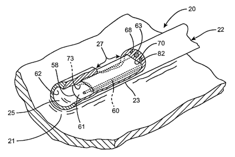
Turning generally now to FIGURES lA-2D, an ablation system, generally
designated
20, is provided for transmurally ablating a targeted tissue 21 of biological
tissue. The
1 S system 20 is particularly suitable to ablate the epicardial or endocardial
tissue 40 of
the heart, and more particularly, to treat medically refractory atrial
fibrillation of the
Heart. The ablation system 20 for ablating tissue within a body of a patient
includes
an elongated flexible tubular member 22 having at least one lumen 25 (FIGURES
1A,
1B, 8 and 9) and including a pre-shaped distal end portion (E.g., FIGURES 2C,
6 and
7) which is shaped to be positioned adjacent to or in contact with a selected
tissue
region 21 within the body of the patient. An ablative device, generally
designated 26,
is configured to be slideably received longitudinally within the at least one
lumen 2S,
and includes an energy delivery portion 27 located near a distal end portion
of the
ablative device 26 which is adapted to be coupled to an ablative energy source
(not
2S shown).
The ablative device is preferably provided by a microwave ablation device 26
formed
to emit microwave energy sufficient to cause tissue ablation. As will be
described in
greater detail below, however, the ablative device energy may be provided by a
laser
ablation device, a Radio Frequency (RF) ablation device, an ultrasound
ablation
device or a cryoablation device.
11
CA 02433416 2003-06-27
WO 03/053259 PCT/USO1/49686
The tubular member 22 is in the form of an elongated ablation sheath having,
in a
preferred embodiment, a resiliently preformed shape adapted to substantially
conform
a predetermined contact surface 23 of the sheath with the targeted tissue
region 21. In
another embodiment, the ablation sheath is malleable. Yet, in another
embodiment,
S the ablation sheath is flexible. The lumen 25 of the tubular member extends
therethrough along an ablation path proximate to the predetermined contact
surface.
Preferably, as will be described in more detail below, the ablative device 26
includes a
flexible energy delivery portion 27 selectively generating an electromagnetic
field
which'is sufficiently strong for tissue ablation. The energy delivery portion
27 is
formed and dimensioned for longitudinal sliding receipt through the ablation
lumen
25 of the ablation sheath 22 for selective placement of the energy delivery
portion
along the ablation path. The ablation lumen 25 and the ablative device 26
cooperate
to position the energy delivery portion 27 proximate to the ablation sheath 22
predetermined contact surface 23 of the sheath for selective transmural
ablation of the
targeted tissue 21 within the electromagnetic field when the contact surface
23
strategically contacts or is positioned close enough to the targeted tissue
21.
Accordingly, in one preferred embodiment, the pre-shaped ablation sheath 22
functions to unidirectionally guide or position the energy delivery portion 27
of the
ablative device 26 properly along the predeterrizined ablation path 28
proximate to the
targeted tissue region 21 as the energy delivery portion 27 is advanced
through the
ablation lumen 25. By positioning the energy delivery portion 27, which is
preferably
adapted to emit a directional ablation field, at one of a plurality of
positions
incrementally along the ablation path (FIGURES 1A and 1B) in the lumen 25, a
single
continuous or plurality of spaced-apart lesions can be formed. In other
instances, the
antenna length may be sufficient to extend along the entire ablation path 28
so that
only a single ablation sequence is necessary.
While the method and apparatus of the present invention are applicable to
ablate any
biological tissue which requires the formation of controlled lesions (as will
be
described in greater detail below), this ablation system is particularly
suitable fox
ablating endocardial or epicardial tissue of the Heart. For example, the
present
invention may be applied in an intra-coronary configuration where the ablation
12 -
CA 02433416 2003-06-27
WO 03/053259 PCT/USO1/49686
procedure is performed on the endocardium of any cardiac chamber.
Specifically,
such ablations may be performed on the isthmus to address atrial flutter, or
around the
pulmonary vein ostium, electrically isolating the pulmonary veins, to treat
medically
refractory atrial fibrillation (FIGURE 3). This procedure requires the precise
formation of strategically placed endocardial lesions 30-36 which collectively
isolate
the targeted regions. By way of example, any of the pulmonary veins may be
collectively isolated to treat chronic atrial fibrillation. The annular lesion
isolating
one or more than one pulmonary vein can be linked with another linear lesion
joining
the mitral valve annulus. In another example, the annular lesion isolating one
or more
than one pulmonary vein can be linked with another linear lesion joining the
left
atrium appendage.
In a preferred embodiment, the pre-shaped ablation sheath 22 and the sliding
ablative
device 26 may applied to ablate the epicardial tissue 39 of the Heart 40 as
well'
(FIGURE 12). An annular ablation, for instance, may be formed around the
pulmonary vein for electrical isolation from the left atrium. As another
example, the
lesions may be created along the transverse sinus and oblique sinus as part of
the
collective ablation pattern to treat atrial fibrillation for example.
The application of the present invention, moreover, is preferably performed
through
minimally invasive techniques. It will be appreciated, however, that the
present
invention may be applied through open chest techniques as well.
Briefly, to illustrate the operation of the present invention, a flexible pre-
shaped
tubular member (i.e., ablation sheath 22) in the form of a pigtail is shown in
FIGURES 2C and 2d which is specifically configured to electrically isolate a
pulmonary vein of the Heart 40. The isolating lesions are preferably made on
the
posterior wall of the left atrium, around the ostium of one, or more than one
of a
pulmonary vein.
In this example and as illustrated in FIGURES 4A and 4B, a distal end of the
pigtail-
shaped ablation sheath or tubular member 22 is positioned into 'the left
superior
pulmonary vein orifice 37 fiom the left atrium 41. As the ablation sheath 22
is further
13
CA 02433416 2003-06-27
WO 03/053259 PCT/USO1/49686
advanced, a predetermined contact surface 23 of the ablation sheath is urged
adjacent
to or into contact with the endocardial surface of the targeted tissue region
21
(FIGURES 2D and 4B). Once the ablation sheath 22 is properly positioned and
oriented, the ablative device 26 is advanced through the ablation lumen 25 of
the
ablation sheath 22 (FIGURES 1A and 1B) which moves the energy delivery portion
27 of the ablative device along the ablation path. When the energy delivery
portion
27 is properly oriented and positioned in the ablation lumen 25, the
directional
ablation field may be generated to incrementally ablate (FIGURES 13A-13D) the
epicardial surface of the targeted tissue 21 along the ablation path to
isolate the Left
Superior Pulmonary Vein (LIPV)
Accordingly, as shown in FIGURES 13A-13D, as the energy delivery portion 27 is
incrementally advanced through the lumen 25, overlapping lesion sections 44-
44"' are
formed by the ablation field which is directional in one preferred embodiment.
Collectively, a continuous lesion or series of lesions can be formed which
essentially
three-dimensionally "mirror" the shape of the contact surface 23 of the
ablation sheath
22 which is positioned adjacent to or in contact with the targeted tissue
region. These
transmural lesions may thus be formed in any shape on the targeted tissue
region such
as rectilinear, curvilinear or circular in shape. Further, depending upon the
desired
ablation lines pattern, both opened and closed path formation can be
constructed.
Refernng now to FIGURES 2A, 2D and 5, a minimal invasive application of the
present invention is illustrated for use in ablating Heart tissue. By way of
example, a
conventional transseptal piercing sheath 42 is introduced into the femoral
vein 43
through a venous cannula 45 (FIGURE 5). The piercing sheath is then
intravenously
advanced into the right atrium 46 of the Heart 40 through the inferior vena
cava
orifice 47. These piercing sheaths are generally resiliently pre-shaped to
direct a
conventional piercing device 48 toward the septum wall 50. The piercing device
48
and the piercing sheath 42 are manipulatively oriented and further advanced to
pierce
through the septum wall 50, as a unit, of access into the left atrium 41 of
the Heart 40
(FIGURE 2A).
14
CA 02433416 2003-06-27
WO 03/053259 PCT/USO1/49686
These conventional devices are commonly employed in the industry for accessing
the
left atrium or ventricle, and have an outer diameter in the range of about
0.16 inch to
about 0.175 inch, while having an inner diameter in the range of about 0.09
inch to
about 0.135 inch.
Once the piercing device 48 is withdrawn from a positioning passage 51 (FIGURE
8)
of the piercing sheath 42, a guide sheath 52 of the ablation system 20 is
slideably
advanced through the positioning passage and into a cardiac chamber such as
the left
atrium 41 thereof (FIGURE 2B). The guide sheath 52 is essentially a pre-
shaped,
open-ended tubular member which is inserted into the coronary circulation to
direct
and guide the advancing ablation sheath 22 into a selected cardiac chamber
(i.e., the
left atrium, right atrium, left ventricle or right ventricle) and toward the
general
direction of the targeted tissue. Thus, the guide sheath 52 and the ablation
sheath 22
telescopically cooperate to position the predetermined contact surface 23
thereof
substantially adjacent to or in contact with the targeted tissue region.
Moreover, the guide sheath and the ablation sheath cooperate to increase the
structural
stability of the system as the ablation sheath is rotated and manipulated from
its
proximal end into ablative contact with the targeted tissue 21 (FIGURE 2A). As
the
distal curved portions of the ablation sheath 22, which is inherently longer
than the
guide sheath, is advanced past the distal lumen opening of the guide sheath,
these
resilient curved portions will retain their original unrestrained shape.
The telescopic effect of these two sheaths is used to position the contact
surface 23 of
the ablation sheath 22 substantially adjacent to or in contact with the
targeted tissue.
Thus, depending upon the desired lesion formation, the same guide sheath 52
may be
employed for several different procedures. For example, the lesion 30
encircling the
left superior pulmonary vein ostium and the Left Inferior Pulmonary Vein
Ostium
(RIPVO) lesion 31 (FIGURE 3) may be formed through the cooperation of the
pigtail
ablation sheath 22 and the same guide sheath 52 of FIGURE' 2B and 2D, while
the
same guide sheath may also be utilized with a different ablation sheath 22
(FIGURE
4) to create the long linear lesion 34 as shown in FIGURE 3.
CA 02433416 2003-06-27
WO 03/053259 PCT/USO1/49686
In contrast, as illustrated in FIGURE 7, another guide sheath 52 having a
different
pre-shaped distal end section may be applied to direct the advancing ablation
sheath
22 back toward the in the left and right superior pulmonary vein orifices 53,
55. Thus,
several pre-shaped guide sheaths, and the corresponding ablation sheaths, as
will be
described, cooperate to create a predetermined pattern of lesions (E.g., a
MAZE
procedure) on the tissue.
In the preferred embodiment, the guide sheath 52 is composed of a flexible
material
which resiliently retains its designated shape once external forces urged upon
the
sheath are removed. These external forces, fox instance, are the restraining
forces
caused by the interior walls 56 of the transseptal piercing sheath 42 as the
guide
sheath S2 is advanced or retracted therethrough. While the guide sheath 52 is
flexible,
it must be sufficiently rigid so as to substantially retain its original
unrestrained shape,
and not to be adversely influenced by the ablation sheath 22, as the ablation
sheath is
advanced through the lumen of the guide sheath. Such flexible, biocompatible
materials may be composed of braided Pebax or the like having an outer
diameter
formed and dimensioned for sliding receipt longitudinally through the
positioning
passage 51 of the transseptal piercing sheath 42. The outer dimension is
therefore
preferably cylindrical having an outer diameter in the range of about 0.09
inch to
about 0.145 inch, and more preferably about 0.135", while having an inner
diameter
in the range of about 0.05 inch to about 0.125 inch, and more preferably about
0.115".
This cylindrical dimension enables longitudinal sliding receipt, as well as
axial
rotation, in the positioning passage 51 to properly place and advance the
guide sheath
52. Thus, the dimensional tolerance between the cylindrical-shaped, outer
peripheral
wall of the guide sheath 52 and the interior walls 56 of the transseptal
piercing sheath
42 should be sufficiently large to enable reciprocal movement and relative
axial
rotation therebetween, while being sufficiently small to substantially prevent
lateral
displacement therebetween as the ablation sheath 22 is urged into contact with
the
targeted tissue 21. For example, the dimensional tolerance between the
transverse
cross-sectional periphery of the interior walls 56 of the positioning passage
51 and
that of the substantially conforming guide sheath 52 should be in the range of
about
0.005 inches to about 0.020 inches.
16
CA 02433416 2003-06-27
To increase the structural integrity of the guide sheath 52, metallic braids
57 are
preferably incorporated throughout the sheath when the guide sheath is molded
to its
preformed shape. These braids 57 are preferably provided by 0.002" wires
composed
of 304 stainless steel evenly spaced about the sheath.
Once the guide sheath 52 is properly positioned and oriented relative the
transseptal
sheath 42, the ablation sheath 22 is advanced through a guide lumen 54 (FIGURE
8)
of the guide sheath 52 toward the targeted tissue. Similar to the pre-shaped
guide
sheath 52, the ablation sheath 22 is pre-shaped in the form of the desired
lesions to be
formed in the endocardial surface of the targeted tissue 21. As best viewed in
FIGURES 2D, 6 and 7, each ablation sheath 52 is adapted facilitate an ablation
in the
targeted tissue 21 generally in the shape thereof. Thus, several pre-shaped
ablation
sheaths cooperate to form a type of steering system to position the ablation
device
about the targeted tissue. Collectively, a predetermined pattern of linear and
curvilinear lesions (E.g., a MAZE procedure) can be ablated on the targeted
tissue
region.
Again, similar to the guide sheath 52, the ablation sheath 22 is composed of a
flexible
material which resiliently retains its designated shape once external forces
urged upon
the sheath are removed. These external forces, for instance, are the
restraining forces
caused by the interior walls 59 defining the guide lumen 54 of the guide
sheath 52 as
the ablation sheath 22 is advanced or retracted therethrough. Such flexible,
biocompatible materials may be composed of Pebax or the like having an outer
diameter formed and dimensioned for sliding receipt longitudinally through the
guide
lumen 54 of the ablation sheath 22. As mentioned, the inner diameter of the
guide
lumen 54 is preferably in the range of about 0.050 inch to about 0.125 inch,
and more
preferably about 0.115", while the ablation sheath 26 has an outer diameter in
the
range of about 0.40 inch to about 0.115 inch, and more preferably about
0.105".
The concentric cylindrical dimensions enable longitudinal sliding receipt, as
well as
axial rotation, of the ablation sheath 22 in the guide lumen 54 to properly
place and
advance the it toward the targeted tissue 21. Thus, the dimensional tolerance
between
the cylindrical-shaped, outer peripheral wall of the ablation sheath 22 and
the interior
17
CA 02433416 2003-06-27
WO 03/053259 PCT/USO1/49686
walls 59 of the guide lumen 54 of the guide sheath 52 should be sufficiently
large to
enable reciprocal movement and relative axial rotation therebetween, while
being
sufficiently small to substantially prevent lateral displacement therebetween
as the
ablation sheath 22 is urged into contact with the targeted tissue 21. For
example, the
dimensional tolerance between the transverse cross-sectional periphery of the
guide
lumen 54 and that of the substantially conforming energy delivery portion 27
should
be in the range of about 0.001 inches to about 0.005 inches.
As above-indicated, the pre-shaped ablation sheath 22 facilitates guidance of
the
ablative device 26 along the predetermined ablation path 28. This is primarily
performed by advancing the energy delivery portion 27 of the ablative device
26
through the ablation lumen 25 of the ablation sheath 22 which is preferably
off set
from the longitudinal axis 78 thereof. As best viewed in FIGURES 8 and 9, this
off
set positions the energy delivery portion 27 relatively closer to the
predetermined
contact surface 23 of the ablation sheath 22, and hence the targeted tissue
21.
Moreover, when using directional fields such as those emitted from their
energy
delivery portion 27, it is important to provide a mechanism for continuously
aligning
the directional field of the energy delivery portion 27 with the tissue 21
targeted for
ablation. Thus, in this design, the directional field must be continuously
aligned with
the predetermined contact surface 23 of the ablation sheath 22 as the energy
delivery
portion 27 is advanced through the ablation lumen 25 since the ablation sheath
contact
surface 23 is designated to contact or be close enough to the targeted tissue.
If the directional field is not aligned correctly, for example, the energy may
be .
transmitted into surrounding fluids and tissues designated for preservation
rather than
into the targeted tissue region. Therefore, in accordance with another aspect
of the
present invention, a lcey structure 48 (FIGURES 1, 8 and 9) cooperates between
the
ablative device 26 and the ablation lumen 25 to orient the directive energy
delivery
portion 27 of the ablative device continuously toward the targeted tissue
region 21 as
it is advanced through the lumen. This key structure 48, thus, only allows
receipt of
the energy delivery portion 27 in the lumen in one orientation. More
particularly, the
key structure 48 continuously aligns a window portion 58 of the energy
delivery
portion 27 substantially adjacent the predetermined contact surface 23 of the
ablation
18
CA 02433416 2003-06-27
WO 03/053259 PCT/USO1/49686
sheath 22 during advancement. This window portion 58, as will be described
below,
enables the transmission of the directed ablative energy from the energy
delivery
portion 27, through the contact surface 23 of the ablation sheath 22 and into
the
targeted tissue region. Consequently, the directional ablative energy emitted
from the
energy delivery portion will always be aligned with the contact surface 23 of
the
ablation sheath 22, which is positioned adjacent to or in contact with the
targeted
tissue region 21, to maximize ablation efficiency. By comparison, the ablation
sheath
22 is capable of relatively free rotational movement axially in the guide
lumen 54 of
the guide sheath 52 for maneuverability and positioning of the ablation sheath
therein.
As mentioned, the transverse cross-sectional dimension of the energy delivery
portion
27 is configured for sliding receipt in the ablation lumen 25 of the ablation
sheath 22
in a manner positioning the directional ablative energy, emitted by the energy
delivery
portion, continuously toward the predetermined contact surface 23 of the
ablation
sheath 22. In one example, as shown in FIGURES 8 and 9, the transverse
peripheral
dimensions of the energy delivery portion 27 and the ablation lumen 25 are
generally
D-shaped, and substantially similar in dimension. Thus, the window portion 58
of the
insulator 61, as will be discussed, is preferably semi-cylindrical and
concentric with
the interior wall 62 defining the ablation lumen 25 of the ablation sheath 22.
It will be
appreciated, however, that any geometric configuration may be applied to
ensure
unitary or aligned insertion. As another example, one of the energy delivery
portion
and the interior wall of the ablation lumen may include a key member and
corresponding receiving groove, or the like. Such key and receiving groove
designs,
nonetheless, should avoid relatively sharp edges to enable smooth advancement
and
retraction of the energy delivery portion in the ablation lumen 25.
This dimension alignment relationship can be maintain along the length of the
predetermined contact surface of the ablation sheath 22 as the energy delivery
portion
27 is advanced through the ablation lumen whether in the configuration of
FIGURES
2, 6, 7 or 12. In this manner, a physician may determine that once the
predetermined
contact surface 23 of the ablation sheath 22 is properly oriented and
positioned
adjacent or in contact against the targeted tissue 21, the directional
component (as will
be discussed) of the energy delivery portion 27 will then be automatically
aligned with
19
CA 02433416 2003-06-27
WO 03/053259 PCT/USO1/49686
the targeted tissue as it is advanced through the ablation lumen 25. Upon
selected
ablation by the ablative energy, a series of overlapping lesions 44-44"'
(FIGURES
13A-13D) or a single continuous lesion can then be generated.
It will further be appreciated that the dimensional tolerances therebetween
should be
sufficiently large to enable smooth relative advancement and retraction of the
energy
delivery portion 27 around curvilinear geometries, and further enable the
passage of
gas therebetween. Since the ablation lumen 25 of the ablation sheath 22 is
closed
ended, gases must be permitted to flow between the energy delivery portion 27
and
the interior wall 62 defining the ablation lumen 25 to avoid the compression
of gas
during advancement of the energy delivery portion therethrough. Moreover, the
tolerance must be sufficiently small to substantially prevent axial rotation
of the
energy delivery portion in the ablation lumen 25 for alignment purposes. The
dimensional tolerance between the transverse cross-sectional periphery of the
ablation lumen and that of the substantially conforming energy delivery
portion 27 ,
for instance, should be in the range of about 0.001 inches to about 0.005
inches.
To further facilitate preservation of the fluids and tissues along the
backside of the
ablation sheath 22 (i.e., the side opposite the contact surface 23 of the
sheath), a
thermal isolation component (not shown) is disposed longitudinally along, and
substantially adjacent to, the ablation lumen 25. Thus, during activation of
the
ablative device, the isolation component and the directive component 73 of the
energy
ablation portion 27 cooperate to form a themnal barrier along the backside of
the
ablation sheath.
For instance, the isolation component may be provided by an air filled
isolation lumen
extending longitudinally along, and substantially adjacent to, the ablation
lumen 25.
The cross-sectional dimension of the isolation lumen may be C-shaped or
crescent
shaped to partially surround the ablation lumen 25. In another embodiment, the
isolation lumen may be filled with a thermally refractory material.
In still another embodiment, a circulating fluid, which is preferably
biocompatible,
may be disposed in the isolation lumen to provide to increase the thermal
isolation.
CA 02433416 2003-06-27
WO 03/053259 PCT/USO1/49686
Two or more lumens may be provided to increase fluid flow. One such
biocompatible
fluid providing suitable thermal properties is saline solution.
Similar to the composition of the guide sheath 52, the ablation sheath 22 is
composed
S of a flexible bio-compatible material, such as PU Pellethane, Teflon or
polyethylent,
which is capable of shape retention once external forces acting on the sheath
are
removed. By way of example, when the distal portions of the ablation sheath 22
are
advanced past the interior walls of the guide lumen 54 of the guide sheath 52,
the
ablation sheath 22 will return to its prefonned shape in the interior of the
Heart.
To facilitate shape retention, the ablation sheath 22 preferably includes a
shape
retaining member 63 extending longitudinally through the distal poz-tions of
the
ablation sheath where shape retention is necessary. As illustrated in FIGURES
1, 8
and 9, this retaining member 63 is generally extends substantially parallel
and
adjacent to the ablation lumen 25 to reshape the predetermined contact surface
23 to
its desired pre-shaped form once the restraining forces are removed from the
sheath.
While this shape-memory material must be sufficiently resilient for shape
retention, it
must also be sufficiently bendable to enable insertion through the guide lumen
54 of
the guide sheath 52. In the preferred form, the shape retaining member is
composed
of a superelastic metal, such as Nitinol (NiTi). Moreover, the preferred
diameter of
this material should be in the range of 0.020 inches to about 0.050 inches,
and more
preferably about 0.035 inches.
When used during a surgical procedure, the ablation sheath 22 is preferably
transparent which enables a surgeon to visualize the position of the energy
delivery
portion 27 of the ablative device 26 through an endoscope or the like.
Moreover, the
material of ablation sheath 22 must be substantially unaffected by the
ablative energy
emitted by the energy delivery portion 27. Thus, as will be apparent,
depending upon
the type of energy delivery portion and the ablative source applied, the
material of the
tubular sheath must exhibit selected properties, such as a low loss tangent,
low water
absorption or low scattering coefficient to name a few, to be unaffected by
the ablative
energy.
21
CA 02433416 2003-06-27
WO 03/053259 PCT/USO1/49686
As previously indicated, the ablation sheath 22 is advanced and oriented,
relative to
the guide sheath 52, adj acent to or into contact with the targeted tissue
region 21 to
form a series of over-lapping lesions 44-44"', such as those illustrated in
FIGURES 3
and 13A-13D. Preferably, the contact surface 23 of the pre-shaped ablation
sheath 22
is negotiated into physical contact with the targeted tissue 21. Such contact
increases
the precision of the tissue ablation while further facilitating energy
transfer between
the ablation element and the tissue to be ablated, as will be discussed.
To assess proper contact and positioning of the contact surface 23 of the
ablation
sheath 22 against the targeted tissue 21, at least one positioning electrode,
generally
designated 64, is disposed on the exterior surface of the ablation sheath for
contact
with the tissue. Preferably a plurality of electrodes are positioned along and
adjacent
the contact surface 23 to assess contact of the elongated and three
dimensionally
shaped contact surface. These electrodes 64 essentially measure whether there
is any
electrical activity (or electrophysiological signals) to one or the other side
of the
ablation sheath 22. When a strong electrical activation signal is detected, or
inter-
electrode impedance is measured when two or more electrodes are applied,
contact
with the tissue can be assessed. Once the physician has properly situated and
oriented
the sheath, they may commence advancement of the energy delivery portion 27
through the ablation lumen 25. Additionally, these positioning electrodes may
be
applied to map the biological tissue prior to or after an ablation procedure,
as well as
be used to monitor the patient's condition during the ablation process.
To facilitate discussion of the above aspects of the present invention, FIGURE
10
illustrates two side-by-side electrodes 64, 65 configured for sensing
electrical activity
in substantially one direction, in accordance with one aspect of the present
invention.
This electrode arrangement generally includes a pair of longitudinally
extending
electrode elements 66, 67 that are disposed on the outer periphery of the
ablation
sheath 22. The pair of electrode elements 66, 67 are positioned side by side
and
arranged to be substantially parallel to one another. In general, splitting
the electrode
arrangement into a pair of distinct elements permits substantial improvements
in the
resolution of the detected electrophysiological signals. Therefore, the pair
of
electrode elements 66, 67 are preferably spaced apart and electrically
isolated from
22
CA 02433416 2003-06-27
WO 03/053259 PCT/USO1/49686
one another. It will be appreciated, however, that only one electrode may be
employed to sense proper tissue contact. It will also be appreciated that ring
or coiled
electrodes can also be used.
The pair of electrode elements 66, 67 are further arranged to be substantially
parallel
to the longitudinal axis of the ablation sheath 22. In order to ensure that
the electrode
elements are sensing electrical activity in substantially the same direction,
the space
between electrodes should be sufficiently small. It is generally believed that
too large
space may create problems in determining the directional position of the
catheter and
too small a space may degrade the resolution of the detected
electrophysiological
signals. By way of example, the distance between the two pair of electrode
elements
may be between about 0.5 and 2.0 mm.
The electrode elements 66, 67 are preferably positioned substantially
proximate to the
predetermined contact surface 23 of the ablation sheath 22. More preferably,
the
electrode elements 66, 67 are positioned just distal to the distal end of the
predetermined contact surface 23 since it is believed to be particularly
useful to
facilitate mapping and monitoring as well as to position the ablation sheath
22 in the
area designated for tissue ablation. For example, during some procedures, a
surgeon
may need to ascertain where the distal end of the ablation sheath 22 is
located in order
to ablate the appropriate tissues. In another embodiment, the electrode
elements 66,
67 may be positioned substantially proximate the proximal end of the
predetermined
contact surface 23, at a central portion of the contact surface 23 or a
combination
thereof. For instance, when attempting to contact the loop-shaped ablation
sheath 22
employed to isolate each of left and inferior pulmonary vein orifices 37, 38,
a central
location of the electrodes along the looped-shape contact surface 23 may best
sense
contact with the targeted tissue. Moreover, while not specifically
illustrated, a
plurality of electrode arrangements may be disposed along the ablation sheath
as well.
By way of example, a first set of electrode elements may be disposed distally
from the
predetermined contact surface, a second set of electrode elements may be
disposed
proximally to the contact surface, while a third set of electrode elements may
be
disposed centrally thereof. These electrodes may also be used with other types
of
mapping electrodes, for example, a variety of suitable mapping electrode
23
CA 02433416 2003-06-27
WO 03/053259 PCT/USO1/49686
arrangements are described in detail in U.S. Patent No. 5,788,692 to Campbell,
et al.,
which is incorporated herein by reference in °its entirety. Although
only a few
positions have been described, it should be understood that the electrode
elements
may be positioned in any suitable position along the length of the ablation
sheath.
The electrode elements 66, 67 may be formed from any suitable material, such
as
stainless steel and iridium platinum. The width (or diameter) and the length
of the
electrode may vary to some extent based on the particular application of the
catheter
and the type of material chosen. Furthermore, in the preferred embodiment
where
microwave is used as the ablative energy, the electrodes are preferably
dimensioned to
minimize electromagZletic field interference, for example, the capturing of
the
microwave field produced by~ the antenna. In most embodiments, the electrodes
are
arranged to have a length that is substantially larger than the width, and are
preferably
between about 0.010 inches to about 0.025 inches and a length between about
0.50
inch to about 1.0 inch.
Although the electrode arrangement has been shown and described as being
parallel
plates that are substantially parallel to the longitudinal axis of the
ablation sheath 22
and aligned longitudinally (e.g., distal and proximal ends match up), it
should be
noted that this is not a limitation and that the electrodes can be configured
to be
angled relative to the longitudinal axis of the ablation sheath 22 (or one
another) or
offset longitudinally. Furthermore, although the electrodes have been shown
and
described as a plate, it should be noted that the electrodes may be configured
to be a
wire or a point such as a solder blob.
Each of the electrode elements 66, 67 is electrically coupled to an associated
electrode
wire 68, 70 and which extend through ablation sheath 22 to at least the
proximal
portion of the flexible outer tubing. Tn most embodiments, the electrode wires
68, 70
are electrically isolated from one another to prevent degradation of the
electrical
signal, and are positioned on opposite sides of the retaining member 63. The
connection between the electrodes 64, 65 and the electrode wires 68, 70 may be
made
in any suitable manner such as soldering, brazing, ultrasonic welding or
adhesive
bonding. In other embodiments, the longitudinal electrodes can be formed from
the
24
CA 02433416 2003-06-27
WO 03/053259 PCT/USO1/49686
electrode wire itself. Forming the longitudinal electrodes from the electrode
wire, or
out of wire in general, is particularly advantageous because the size of wire
is
generally small and therefore the longitudinal electrodes elements may be
positioned
closer together thereby forming a smaller arrangement that takes up less
space. As a
result, the electrodes may be positioned almost anywhere on a catheter or
surgical
tool. These associated electrodes are described in greater detail in U.S.
Patent
Application S/N: 09/548,331, filed April 12, 2000, and entitled "ELECTRODE
ARRANGE-MENT FOR USE IN A MEDICAL INSTRUMENT", and incorporated
by reference.
Referring now to FIGURES 1, 8, 9 and 11, the ablative device 26 is preferably
in the
form of an elongated member, which is designed for insertion into the ablation
lumen
25 of the ablation sheath 22, and which in turn is designed for insertion into
a vessel
(such as a blood vessel) in the body of a patient. It will be understood,
however, that
the present invention may be in the form of a handheld instrument for use in
open
surgical or minimally invasive procedures (FIGURE 12).
The ablative device 26 typically includes a flexible outer tubing 71 (having
one or
several lumens therein), a transmission line 72 that extends through the
flexible tubing
71 and an energy delivery portion 27 coupled to the distal end of the
transmission line
72. The flexible outer tubing 71 may be made of any suitable material such as
medical grade polyolefms, fluoropolymers, or polyvinylidene fluoride. By way
of
example, PEBAX resins from Autochem of Germany have been used with success for
the outer tubing of the body of the catheter.
In accordance with another aspect of the present invention, the ablative
energy emitted
by the energy delivery portion 27 of the ablative device 26 may be one of
several
types. Preferably, the energy delivery portion 27 includes a microwave
component
which generates a electromagnetic field sufficient to cause tissue ablation.
As
mentioned, as will be discussed in greater detail below, the ablative energy
may also
be derived from a laser source, a cryogenic source, an ultrasonic source or a
radiofrequency source, to name a few.
CA 02433416 2003-06-27
WO 03/053259 PCT/USO1/49686
Regardless of the source of the energy, a directive component cooperates with
the
energy source to control the direction and emission of the ablative energy.
This
assures that the surrounding tissues of the targeted tissue regions will be
preserved.
Further, the use of a directional field has several potential advantages over
conventional energy delivery structure that generate uniform fields about the
longitudinal axis of the energy delivery portion. For example, in the
microwave
application, by forming a more concentrated and directional electromagnetic
field,
deeper penetration of biological tissues is enabled, and the targeted tissue
region may
be ablated without heating as much of the surrounding tissues and/or blood.
Additionally, since substantial portions the radiated ablative energy is not
emitted in
the air or absorbed in the blood or the surrounding tissues , less power is
generally
required from the power source, and less power is generally lost in the
microwave
transmission line.
In the preferred form, the energy delivery portion 27 of the ablative device
26 is an
antenna assembly configured to directionally emit a majority of an
electromagnetic
field from one side thereof. The antenna assembly 27, as shown in FIGURES 9
and
1 l, preferably includes a flexible antenna 60, for generating the
electromagnetic field,
and a flexible reflector 73 as a directive component, for redirecting a
portion of the
electromagnetic field to one side of the antenna opposite the reflector.
Correspondingly, the resultant electromagnetic field includes components of
the
originally generated field, and components of the redirected electromagnetic
field.
During aligned insertion of the antenna assembly 27 into the ablation lumen
25, via
the key structure 48, the directional field will thus be continuously aligned
toward the
contact surface 23 of the ablation sheath 22 as the antenna assembly is
incrementally
advanced through the ablation lumen 25.
FIGURE 11 illustrates that the proximal end of the antenna 60 is preferably
coupled
directly or indirectly to the inner conductor 75 of a coaxial transmission
line 72. A
direct connection between the antemia 60 and the inner conductor 75 may be
made in
any suitable manner such as soldering, brazing, ultrasonic welding or adhesive
bonding. In other embodiments, antemla 60 can be formed from the inner
conductor
75 of the transmission line 72 itself. This is typically more difficult from a
26
CA 02433416 2003-06-27
WO 03/053259 PCT/USO1/49686
manufacturing standpoint but has the advantage of forming a more rugged
connection
between the antenna and the imzer conductor. As will be described in more
detail
below, in some implementations, it may be desirable to indirectly couple the
antenna
to the inner conductor through a passive component, such a capacitor, an
inductor or a
stub tuner for example, in order to provide better impedance matching between
the
antenna assembly and the transmission line, which is a coaxial cable in the
preferred
embodiment.
Briefly, the transmission line 72 is arranged for actuating and/or powering
the antenna
60. Typically, in microwave devices, a coaxial transmission line is used, and
therefore, the transmission line 72 includes an inner conductor 75, an outer
conductor
76, and a dielectric material 77 disposed between the inner and outer
conductors. In
most instances, the inner conductor 75 is coupled to the antenna 60. Further,
the
antenna 60 and the reflector 73 are enclosed (e.g., encapsulated) in a
flexible
insulative material thereby forming the insulator 61, to be described in
greater detail
below, of the antenna assembly 27.
The power supply (not shown) includes a microwave generator which may take any
conventional form. When using microwave energy for tissue ablation, the
optimal
frequencies are generally in the neighborhood of the optimal frequency for
heating
water. By way of example, frequencies in the range of approximately 800 MHz to
6
GHz work well. Currently, the frequencies that are approved by the Federal
Communication Commission (FCC) for experimental clinical worlc includes 915
MHz
and 2.45 GHz. Therefore, a power supply having the capacity to generate
microwave
energy at frequencies in the neighborhood of 2.45 GHz may be chosen. A
conventional magnetron of the type commonly used in microwave ovens is
utilized as
the generator. It should be appreciated, however, that any other suitable
microwave
power source could be substituted in its place, and that the explained
concepts may be
applied at other frequencies like about 434 MHz or 5.8 GHz (ISM band).
In the preferred embodiment, the antenna assembly 27 includes a longitudinally
extending antenna wire 60 that is laterally offset from the transmission line
inner
conductor 75 to position the antenna closer to the window portion 58 of the
insulator
27
CA 02433416 2003-06-27
61 upon which the directed electric field is transmitted. The antenna 60
illustrated is
preferably a longitudinally extending exposed wire that extends distally
(albeit
laterally offset) from the inner conductor. However it should be appreciated
that a
wide variety of other antenna geometries may be used as well. By way of
example,
helical coils, flat printed circuit antennas and other antenna geometries will
work as
well.
Briefly, the insulator 61 is preferably provided by a good, low-loss
dielectric material
which is relatively unaffected by microwave exposure, and thus capable of
transmission of the electromagnetic field therethrough. Moreover, the
insulator
material preferably has a low water absorption so that it is not itself heated
by the
microwaves. Incidentally, when the emitted ablative energy is microwave in
origin,
the ablation sheath must also include these material properties. Finally, the
insulation
material must be capable of substantial flexibility without fracturing or
breaking.
Such materials include moldable TEFLON~ , silicone, or polyethylene,
polyimide,
etc.
As will be appreciated by those familiar with antemla design, the field
generated by
the illustrated antenna will be generally consistent with the length of the
antenna.
That is, the length of the electromagnetic field is generally constrained to
the
longitudinal length of the antemla. Therefore, the length of the field may be
adjusted
by adjusting the length of the antenna. Accordingly, microwave ablation
elements
having specified ablation characteristics can be fabricated by building them
with
different length antennas. Additionally, it should be understood that
longitudinally
extending antennas are not a requirement and that other shapes and
configurations
may be used.
The antenna 60 is preferably formed from a conductive material. By way of
example,
copper or silver-plated metal work well. Further, the diameter of the antenna
60 may
vary to some extent based on the particular application of the catheter and
the type of
material chosen. In microwave systems using a simple exposed wire type
antenna, for
instance, wire diameters between about 0.010 to about 0.020 inches work well.
In the
illustrated embodiment, the diameter of the antenna is about 0.013 inches.
28
CA 02433416 2003-06-27
WO 03/053259 PCT/USO1/49686
In a preferred embodiment, the antenna 60 is positioned closer to the area
designated
for tissue ablation in order to achieve effective energy transmission between
the
antenna 60 and the targeted tissue 21 through the predetermined contact
surface 23 of
the ablation sheath 22. This is best achieved by placing the antenna 60
proximate to
the outer peripheral surface of the antenna insulator 61. More specifically, a
longitudinal axis of the antenna 60 is preferably off set from, but parallel
to, a
longitudinal axis 78 of the inner conductor 75 in a direction away from the
reflector
73 and therefore towards the concentrated electromagnetic field (FIGURES 8 and
9).
By way of example, placing the antenna between about 0.010 to about 0.020
inches
away from the outer peripheral surface of the antenna insulator works well. In
the
illustrated embodiment, the antenna is about 0.013 inches away from the outer
peripheral surface of the antenna insulator 61. However, it should be noted
that this is
not a requirement and that the antenna position may vary according to the
specific
design of each catheter.
Referring now to the directive component or reflector 73, it is positioned
adjacent and
generally parallel to a first side of the antenna, and is configured to
redirect those
components of the electromagnetic field contacting the reflector back towards
and out
of a second side of the antenna assembly 27 opposite the reflector. A majority
of the
electromagnetic field, consequently, is directed out of the window portion 58
of the
insulator 61 in a controlled manner during ablation.
To reduce undesirable electromagnetic coupling between the antenna and the
reflector
73, the antenna 60 is preferably off set from the reflector 73 (FIGURES 8 and
9).
This off set from the longitudinal axis 78 further positions the antenna 60
closer to the
window portion 58 to facilitate ablation by positioning the antenna 60 closer
to the
targeted tissue region. It has been found that the minimum distance between
the
reflector and the antenna may be between about 0.020 to about 0.030 inches, in
the
described embodiment, in order to reduce the coupling. However, the distance
may
vary according to the specific design of each ablative device.
29
CA 02433416 2003-06-27
WO 03/053259 PCT/USO1/49686
The proximal end of the reflector 73 is preferably coupled to the outer
conductor 76 of
the coaxial transmission line 72. Connecting the reflector to the outer
conductor
serves to better define the electromagnetic field generated during use. That
is, the
radiated field is better confined along the antenna, to one side, when the
reflector is
electrically connected to the outer conductor of the coaxial transmission
line. The
connection between the reflector 73 and the outer conductor 76 may be made in
any
suitable manner such as soldering, brazing, ultrasonic welding or adhesive
bonding. Tm
other embodiments, the reflector can be formed from the outer conductor of the
transmission line itself. This is typically more difficult from a
manufacturing
standpoint but has the advantage of forming a more rugged connection between
the
reflector and the outer conductor.
W one embodiment, to improve flexibility at the electrical connection with the
outer
conductor 76 and entirely along the energy delivery device, the proximal end
of the
reflector 73 is directly contacted against the outer conductor without
applying solder
or such conductive adhesive bonding. In this design, the insulator material of
the
insulator 61 functions as the adhesive to maintain electrical continuity. This
is
performed by initially molding the antenna wire in the silicone insulator. The
reflector 73 is subsequently disposed on the molded silicone tube, and is
extended
over the outer conductor 76 of coaxial cable transmission line 72. A heat
shrinlc tube
is then applied over the assembly to firmly maintain the electrical contact
between the
reflector 73 and the coaxial cable outer conductor 76. In other embodiments,
the
reflector may be directly coupled to a ground source or be electrically
floating.
As previously noted, the antenna 60 typically emits an electromagnetic field
that is
fairly well constrained to the length of the antenna. Therefore, in some
embodiments,
the distal end of the reflector 73 extends longitudinally to at about the
distal end of the
antenna 60 so that the reflector can effectively cooperate with the antenna.
This
arrangement serves to provide better control of the electromagnetic field
during
ablation. However, it should be noted that the actual length of the reflector
may vary
according to the specific design of each catheter. For example, catheters
having
specified ablation characteristics can be fabricated by building catheters
with different
length reflectors.
CA 02433416 2003-06-27
WO 03/053259 PCT/USO1/49686
Furthermore, the reflector 73 is typically composed of a conductive, metallic
material
or foil. However, since the antenna assembly 27 must be relatively flexible in
order to
negotiate the curvilinear ablation lumen 25 of the ablation sheath 22 as the
ablative
device it is advanced therethrough, the insulator 61, the antenna wire and the
reflector
must collectively be relatively flexible. Thus, one particularly material
suitable for
such a reflector is a braided conductive mesh having a proximal end
conductively
mounted to the distal portion of the outer conductor of the coaxial cable.
Tlus
conductive mesh is preferably thin walled to the shield assembly yet provide
the
appropriate microwave shielding properties, as well as enable substantial
flexibility of
the shield device during bending movement. For example, a suitable copper mesh
wire should have a diameter in the range of about 0.005 inches to about 0.010
inches,
and more preferably about 0.007 inches. A good electrical conductor is
generally
used for the shield assembly in order to reduce the self heating caused by
resistive
losses. Such conductors includes, but are not restricted to copper, silver and
gold.
Another suitable arrangement may be thin metallic foil reflector 73 which is
inherently flexible. However, to further increase flexibility, the foil
material can be
pleated or folded which resists tearing during bending of the antenna assembly
27.
These foils can be composed of copper that has a layer of silver plating
formed on its
inner peripheral surface. Such silver plating, which can also be applied to
the metallic
mesh material, is used to increase the conductivity of the reflector. It
should be
understood, however, that these materials are not a limitation. Furthermore,
the actual
thickness of the reflector may vary according to the specific material chosen.
Refernng back to FIGURE 11, the reflector 73 is preferably configured to have
an
arcuate or meniscus shape (e.g., crescent), with an arc angle that opens
towards the
antenna 60. Flaring the reflector towards the antenna serves to better define
the
electromagnetic field generated during use. Additionally, the reflector
functions to
isolate the antenna 60 from the restraining member 63 of the ablation sheath
22 during
ablation. Since the restraining member 63 is preferably metallic in
composition (most
preferably Nitinol), it is desirable minimize electromagnetic coupling with
the
antenna. Thus, the reflector 73 is preferably configured to permit at most a
180°
31
CA 02433416 2003-06-27
WO 03/053259 PCT/USO1/49686
circumferential radiation pattern from the antenna. In fact, it has been
discovered that
arc angles greater than about 180° are considerably less efficient.
More preferably,
the arc angle of the radiation pattern is in the range of about 90° to
about 120°.
While the reflector is shown and described as having an arcuate shape, it will
be
appreciated that a plurality of forms may be provided to accommodate different
antenna shapes or to conform to other external factors necessary to complete a
surgical procedure. For example, any flared shape that opens towards the
antenna
may work well, regardless of whether it is curvilinear or rectilinear.
Further still, it should be noted that the shape of the reflector need not be
uniform.
For example, a first portion of the reflector (e.g., distal) may be configured
with a first
shape (e.g., 90° arc angle) and a second portion (e.g., proximal) of
the reflector may
be configured with a second shape (e.g., 120° arc angle). Varying the
shape of the
reflector in this manner may be desirable to obtain a more uniform radiated
field. It is
believed that the energy transfer between the antenna and the tissue to be
ablated
tends to increase by decreasing the coverage angle of the reflector, and
conversely, the
energy transfer between the antenna and the tissue to be ablated tends to
decrease by
increasing the coverage angle of the reflector. Accordingly, the shape of the
reflector
may be altered to balance out non-uniformities found in the radiated field of
the
antenna arrangement.
In another configuration, the directive component 73 for the microwave antenna
assembly 27 can be provided by another dielectric material having a dielectric
constant different than that of the insulator material 67. Indeed, a strong
reflection of
electromagnetic wave is observed when the wave reaches an interface created by
two
materials with a different dielectric constant. For example, a ceramic loaded
polymer
can have a dielectric constant comprised between 15 and 55, while the
dielectric of a
fluoropolymer like Teflon or is comprised between 2 and 3. Such an interface
would
create a strong reflection of the wave and act as a semi-reflector.
It should also be noted that the longitudinal length of the reflector need not
be
uniform. That is, a portion of the reflector may be stepped towards the
antenna or a
32
CA 02433416 2003-06-27
WO 03/053259 PCT/USO1/49686
portion of the reflector may be stepped away from the antenna. Stepping the
reflector
in this manner may be desirable to obtain a more uniform radiated field. While
not
wishing to be bound by theory, it is believed that by placing the reflector
closer to the
antenna, a weaker radiated field may be obtained, and that by placing the
reflector
further away from the antenna, a stronger radiated field may be obtained.
Accordingly, the longitudinal length of the reflector may be altered to
balance out non
uniformities found in the radiated field of the antenna arrangement. These
associated
reflectors are described in greater detail in U.S. Patent Application S/Ns:
09/178,066,
entitled "DIRECTIONAL REFLECTOR SHIELD ASSEMBLY FOR A
MICROWAVE ABLATION INSTRUMENT, and 09/484,548 entitled "A
MICROWAVE ABLATION INSTRUMENT WITH FLEXIBLE ANTENNA
ASSEMBLY AND METHOD", each of which is incorporated by reference.
In a typical microwave ablation system, it is important to match the impedance
of the
antenna with the impedance of the transmission line. As is well known to those
skilled in the art, if the impedance is not matched, the catheter's
performance tends to
be well below the optimal performance. The decline in performance is most
easily
seen in an increase in the reflected power from the antenna toward the
generator.
Therefore, the components of a microwave transmission system are typically
designed
to provide a matched impedance. By way of example, a typical set impedance of
the
microwave ablation system may be on the order of fifty (50) olnns.
Refernng back to FIGURES 10 and 11, and in accordance with one embodiment of
the present invention, an impedance matching device 80 may be provided to
facilitate
impedance matching between the antenna 60 and the transmission line 72. The
impedance matching device 80 is generally disposed proximate the junction
between
the antenna 60 and the inner conductor 75. For the most part, the impedance
match is
designed and calculated assuming that the antenna assembly 27, in combination
with
the predetermined contact surface 23 of the ablation sheath 22, is in
resonance to
minimize the reflected power, and thus increase the radiation efficiency of
the antenna
structure.
33
CA 02433416 2003-06-27
WO 03/053259 PCT/USO1/49686
In one embodiment, the impedance matching device is determined by using a
Smith
Abacus Model. In the Smith Abacus Model, the impedance matching device may be
ascertained by measuring the impedance of the antenna with a network analyzer,
analyzing the measured value with a Smith Abacus Chart, and selecting the
appropriate device. By way of example, the impedance matching device may be
any
combination of a capacitor, resistor, inductor, stub tuner or stub
transmission line,
whether in series or in parallel with the antenna. An example of the Smith
Abacus
Model is described in Reference: David K. Cheng, "Field and Wave
Electromagnetics," second edition, Addison-Wesley Publishing, 1989, which is
incorporated herein by reference. In one preferred implementation, the
impedance
matching device is a serial capacitor having a capacitance in the range of
about 0.6 to
about 1.0 picoFarads. In the illustration shown, the serial capacitor has a
capacitance
of about 0.8 picoFarads.
As above-mentioned, the impedance will be matched assuming flush contact
between
the antenna assembly 27 and the ablation sheath (FIGURE 9). In accordance with
the
present invention, as the antenna assembly 27 is advanced through the ablation
lumen
25, before selective ablation, it is desirable to position the window portion
58 of the
flexible antemla insulator 61 in flush contact against the interior wall 62 of
the
ablation lumen 25, opposite the predetermined contact surface 23. This
arrangement
may substantially reduce the impedance variance caused by the interface
between
insulator 61 and the ablation sheath 22 as the directional field is
transmitted
therethrough. In comparison, if the window portion 58 were not required to be
positioned in flush contact against the interior wall 62 of the ablation
lumen, pockets
of air or fluid, or the lilce, may be disposed intermittently therebetween
which would
result in a greater degree of impedance variations at this interface.
Consequently, the
above-indicated impedance matching techniques would be less effective.
To assure such flush contact during selective directional ablation and
advancement
along the sheath ablation lumen, the ablation system 20 preferably
incorporates a
forcing mechanism 81 (FIGURES 8 and 9) adapted to urge the window portion 58
of
the antenna assembly 27 into flush contact against the interior wall 62 of the
ablation
sheath. Preferably, the forcing mechanism cooperates between a support portion
82 of
34
CA 02433416 2003-06-27
WO 03/053259 PCT/USO1/49686
the interior wall 62 of the ablation lumen 25 and the forcing wall portion 83
of the
antenna assembly.
When not operational, the forcing mechanism permits relative axial
displacement
between the ablative device 26 and the ablation sheath for repositioning of
the antenna
assembly 27 along the ablation path 28 (FIGURE 8). Upon selective operation,
the
forcing mechanism 81 contacts the forcing wall portion 83 to urge window
portion 58
flush against the interior wall 62 opposite the predetermined contact surface
23.
Consequently, the impedance match between the antenna and the transmission
line is
properly achieved and stable even when the antenna is moving in the ablation
sheath.
hi one embodiment, the forcing mechanism may be provided by an inflatable
structure
acting between the support portion 82 of the interior wall 62 of the ablation
lumen 25
and the forcing wall portion 83 of the antenna assembly device. Upon selective
inflation of forcing mechanism 81 (FIGURE 9), the window portion 58 will be
urged
into flush contact with the interior wall 62 of the ablation lumen. Upon
selective
deflation of the forcing mechanism 81 (FIGURE 8), relative axial displacement
between the antenna assembly 27 and the ablation sheath may commence. The
forcing mechanism can be provided by other techniques such as spring devices
or the
life.
In accordance with another aspect of the present invention, the ablative
energy may be
in the form of laser energy sufficient to ablate tissue. Example of such laser
components include COZ or Nd: YAG lasers. To transmit the beams, the
transmission
line 72 is preferably in the form of a fiber optic cable or the lilce.
In this design, as shown in FIGURES 14A and 14B, the directive component 73
may
be provided by a reflector having a well polished smooth reflective or semi-
reflective
surface. This preferably metallic reflective surface is configured to reflect
the emitted
laser energy toward the targeted tissue region. By way of example, functional
metallic
materials include silver or platinum. In another configuration, similar to the
difference in dielectric constants of the microwave ablation device 26, the
directive
component of the laser ablative device may be provided between two layers of
CA 02433416 2003-06-27
WO 03/053259 PCT/USO1/49686
dielectric materials with a sufficient difference between the refractory
indexes. Here,
at least one dielectric directive component layer functions like the outer
dielectric
layer of the fiber optic transmission line 72 to obtain "total internal
reflection".
Consequently, the laser energy can be emitted away from the dielectric layer.
By
S providing more than one dielectric layer, "total internal reflection" may be
attained at
several angles of incidence. Again, the reflection of the electromagnetic wave
is
caused by the interface between two media having different dielectric
constants.
Generally speaking, the higher is the difference between the dielectric
constants, the
more significant is the internal reflection. In addition, when more than one
dielectric
layer are involved, interference can be used to direct the laser energy in a
preferred
direction.
Moreover, when the ablative energy is laser based, it will be appreciated that
it is
desirable that both the ablation sheath 22 and the ablation device be composed
of
materials which have a low scattering coefficient and a low factor of
absorption. In
addition, it is also preferable to use material with low water absorption.
It will be appreciated that a plurality of designs can be used for the laser
energy
delivery portion. For example, the laser energy delivery portion can consist
of
multiple reflective particles embedded in a laser transparent material. The
laser wave
is propagating from the laser generator to the optic fiber transmission line
and enter in
the laser energy delivery portion. The embedded reflective particles diffracts
the light,
which is reflected toward the tissue to be ablated by the directive component
73.
2S In yet another alteniative embodiment, cryogenic energy may be employed as
an
ablative energy. Briefly, as shown in FIGURES 1 SA and 1 SB, in these
cryogenic
ablation device designs, a cryogenic fluid, such as a pressurized gas (E.g.,
Freon) is
passed through an inflow lumen 90 in the ablation device transmission line 72.
The
distal ablative device 26 is preferably provided by a decompression chamber
which
decompresses the pressurized gas from the inflow lumen 90 therein. Upon
decompression or expansion of the pressurized gas in the decompression chamber
91,
the temperature of the exterior surface 92 of the decompression chamber is
36
CA 02433416 2003-06-27
WO 03/053259 PCT/USO1/49686
sufficiently reduced to cause tissue ablation upon contact thereof. The
decompressed
gas is then exhausted through the outflow lumen 93 of the transmission line
72.
FIGURE 15B illustrates that the directive component 73 is in the form of a
thermal
insulation layer extending longitudinally along one side of the energy
delivery portion
27. By forming a good thermal insulator with a low thermal conductivity, the C-
shaped insulation layer 73 will substantially minimize undesirable cryogenic
ablation
of the irmnediate tissue surrounding of the targeted tissue region. In one
configuration, the isolation layer may define a thin, elongated gap 95 which
partially
surrounds the decompression chamber 91. This gap 95 may then be filled with
air, or
an inert gas, such as CO2, to facilitate thermal isolation. The isolation gap
95 may
also be filled with a powder material having relatively small solid
particulates or by
air expended polymer. These materials would allow small air gaps between the
insulative particles or polymeric matrix for additional insulation thereof.
The
isolation layer may also be provided by a refractory material. Such materials
forming
an insulative barrier include ceramics, oxides, etc.
Referring now to FIGURE 16, an ultrasound ablation device may also be applied
as
another viable source of ablation energy. For example, a piezoelectric
transducer 96
may be supplied as the ablative element which delivers acoustic waves
sufficient to
ablate tissue. These devices emit ablative energy which can be directed and
shaped by
applying a directive echogenic component to reflect the acoustic energy.
Moreover, a
series or array of piezoelectric transducers 96, 96' and 96" can be applied to
collectively form a desired radiation pattern for tissue ablation. For
example, by
~ adjusting the delay between the electrical exciting signal of one transducer
and its
neighbor, the direction of transmission can be modified. Typical of these
transducers
include piezoelectric materials like quartz, barium oxides, etc.
In this configuration, the directive component 73 of the ultrasonic ablation
device may
be provided by an echogenic material (73-73") positioned proximate the
piezoelectric
transducers. This material reflects the acoustic wave and which cooperates
with the
transducers to direct the ablative energy toward the targeted tissue region.
By way of
37
CA 02433416 2003-06-27
WO 03/053259 PCT/USO1/49686
example, such echogenic materials are habitually hard. They include, but are
not
restricted to metals and ceramics for example.
Moreover, when the ablative energy is ultrasonic based, it will be appreciated
that it is
desirable that both the ablation sheath 22 and the ablation device be composed
of
materials which have low absorption of the acoustic waves, and that provide a
good
acoustic impedance matching between the tissue and the transducer. In that
way, the
thiclcness and the material chosen for the ablation sheath play in important
role to
match the acoustic properties of the tissue to be ablated and the transducer.
An
impedance matching jelly can also be used in the ablation sheath to improve
the
acoustic impedance matching.
Lastly, the ablation device may be provided by a radiofrequency (RF) ablation
source
which apply RF conduction current sufficient to ablate tissue. These
conventional
ablation instruments generally apply conduction current in the range of about
450 kHz
to about 550 kHz. Typical of these RF ablation devices include ring
electrodes, coiled
electrodes or saline electrodes.
To selectively direct the RF energy, the directive component is preferably
composed
of an electrically insulative and flexible material, such as plastic or
silicone. These
biocompatible materials perform the function of directing the conduction
current
toward a predetermined direction.
In an alternative embodiment, as best viewed in FIGURE 17, the window portion
58
of the ablation sheath 22 is provided by an opening in the sheath along the
ablation
path, as opposed to being merely transparent to the energy ablation devices.
In this
manner, when the ablation sheath 22 is properly positioned with the window
portion
placed proximate and adjacent the targeted tissue, the energy delivery portion
27 of
the ablation device 26 may be slideably positioned into direct contact with
the tissue
for ablation thereof. Such direct contact is especially beneficial when it is
technically
difficult to find a sheath that is merely transparent to the used ablative
energy. For
example, it would be easier to use a window portion when RF energy is used.
The
ablative RF element could directly touch the tissue to be ablated while the
directive
38
CA 02433416 2003-06-27
WO 03/053259 PCT/USO1/49686
element would be the part of the ablation sheath 22 facing away the window
portion
58. Furthermore, during surgical ablation, the window portion could be used by
the
surgeon to indicate the area where an ablation can potentially be done with
the energy
ablation device.
. In yet another embodiment, the ablation system 20 may be in the form of a
rail system
including a rail device 96 upon which the ablation device 26 slides therealong
as
compared to therethrough. FIGURES 18 and 19 illustrate the rail device 96
which is
preferably pre-shaped or bendable to proximately conform to the surface of the
targeted tissue. Once the rail device 96 is positioned, the ablation device
can be
advanced or retracted along the path defined by the rail device for ablation
of the
targeted tissue 21.
The ablation device 26 in this arrangement includes a body portion 98 housing
the
energy delivery portion 27 therein. The window portion 58 is preferably extend
longitudinally along the outer surface of one side of the housing. An opposite
side of
the housing, and longitudinally oriented substantially parallel to the window
portion
58 is a rail receiving passage 97 formed and dimensioned to slideably receive
and
slide over the rail device 96 longitudinally therethrough. In one
configuration, the
energy delivery portion 27 may be advanced by pushing the body portion 98
through
the transmission line 72. Alternatively, the energy delivery portion 27 may be
advanced by pulling the body portion 98 along the path of the rail system 20.
As best viewed in FIGURE 19, the directive component 73 of the ablation device
26
is integrally formed with the body portion 98 of the ablation device. This
preferably
C-shaped component extends partially peripherally around the energy delivery
portion
27 to shield the rail device 96 from exposure to the ablative energy.
Depending upon
the type of ablative energy employed, the material or structure of the
directive
component 73 can be constructed as set forth above.
To assure the directional position and orientation of the window portion 58 of
the
ablative device toward the targeted tissue, a key structure 48 is employed.
Generally,
the transverse cross-sectional dimension of the rail device 96 and matching
rail
39
CA 02433416 2003-06-27
WO 03/053259 PCT/USO1/49686
receiving passage 97 is shaped to assure proper directional orientation of the
ablative
energy. Examples of such key forms are shown in FIGURES 20A-20B.
As with the previous embodiments, the open window embodiment and the rail
system
embodiment may employ multiple ablative element technology. These include
microwave, radiofrequency, laser, ultrasound and cryogenic energy sources.
In accordance with another aspect of the present invention, the tissue
ablation system
further includes a temperature sensor which is applied to measure the
temperature of
the ablated tissue during the ablation. In one embodiment, the temperature
sensor is
mounted to the ablation device proximate the energy delivery portion 27 so
that the
sensor moves together with the energy delivery portion as it is advanced
through the
ablation sheath. In another embodiment, the temperature sensor is attached on
the
ablation sheath.
To determine the temperature of the ablated tissue, a mathematical
relationship is
used to calculate the tissue temperature from the measured temperature.
Typical of
such temperature sensors include a metallic temperature sensor, a
thermocouple, a
thermistor, or a non-metallic temperature sensor such as fiber optic
temperature
sensor.
In accordance with the present invention, the guide sheath 52 and the ablation
sheath
22 can be designed and configured to steer the ablative device along any three
dimensional path. Thus, the tissue ablation system of present invention may be
adapted for an abundance of uses. For instance, the distal end portion of the
ablation
sheath can be configured to form a closed ablation path for the ablation
device. This
design may be employed to ablate around an ostium of an organ, or to
electrically
isolate one or several pulmonary veins to treat atrial fibrillation. A closed
ablation
path may also utilized to ablate around an aneurysm, such as a cardiac
aneurysm or
tumor, or any kink of tumor. In other example, the ablation sheath can be
inserted in
an organ in order to ablate a deep tumor or to perform any surgical treatment
where a
tissue ablation is required.
CA 02433416 2003-06-27
WO 03/053259 PCT/USO1/49686
In other instances, the distal end portion of the ablation sheath 22 may
define a
rectilinear or curvilinear open .ablation path for the ablation device. Such
open
ablation paths may be applied to ablate on the istlunus between the inferior
caval vein
(IVC) and the tricuspid valve (TV), to treat regular flutter, or to generate a
lesion
between the IVC and the SVC, to avoid macro-reentry circuits in the right
atrium.
Other similar ablation lesions can be formed between: any of the pulmonary
vein
ostium to treat atrial fibrillation; the mitral valve and one of the pulmonary
veins to
avoid macro-reentry circuit around the pulmonary veins in the left atrium; and
the left
appendage and one of the pulmonary veins to avoid macro-reentry circuit around
the
pulmonary veins in the left atrium.
The ablation apparatus may be applied through several techniques. By way of
example, the ablation apparatus may be inserted into the coronary circulation
to
produce strategic lesions along the endocardium of the cardiac chambers (i.e.,
the left
atrium, the right atrium, the left ventricle or the right ventricle).
Alternatively, the
ablation apparatus may be inserted through the chest to produce epicardial
lesions on
the heart. This insertion may be performed through open surgery techniques,
such as
by a sternotomy or a thoracotomy, or through minimally invasive techniques,
applying
a cannula and an endoscope to visualize the location of the ablation apparatus
during a
surgery.
The ablation apparatus is also suitable for open surgery applications such as
ablating
the exterior surfaces of an organ as well, such as the heart, brain, stomach,
esophagus,
intestine, uterus, liver, pancreas, spleen, kidney or prostate. The present
invention
may also be applied to ablate the inside wall of hollow organs, such as heart,
stomach,
esophagus, intestine, uterus, bladder or vagina. When the hollow organ
contains
bodily fluid, the penetration port formed in the organ by the ablation device
must be
sealed to avoid a substantial loss of this fluid. By way of example, the seal
may be
formed by a purse string, a biocompatible glue or by other conventional
sealing
devices.
As mentioned, the present invention may be applied in an intra-coronary
configuration where the ablation device is used to isolate the pulmonary vein
from the
41
CA 02433416 2003-06-27
WO 03/053259 PCT/USO1/49686
left atrium. FIGURE 2G illustrates that a distal end of the ablation sheath 22
is
adapted for insertion into the pulmonary vein. In this embodiment, the distal
end of
the ablation device may include at least one electrode used to assess the
electrical
isolation of the vein. This is performed by pacing the distal electrode to
"capture" the
S heart. If pacing captures the heart, the vein is not yet electrically
isolated, while, if the
heart cannot be captured, the pulmonary vein is electrically isolated from the
left
atrium. As an example, a closed annular ablation on the posterior wall of the
left
atrium around the ostium of the pulmonary vein by applying the pigtail
ablation
sheath 22 of FIGURES 2 and 4.
In yet another configuration, the ablation device may include a lumen to
inject a
contrasting agent into the organ. For instance, the contrasting agent
facilitates
visualization of the pulmonary vein anatomy with a regular angiogram
technique. This
is important for an intra-coronary procedure since fluoroscopy is used in this
technique. The premise, of course, is to visualize the shape and the distal
extremity of
tle sheaths, as well as the proximal and distal part of the sliding energy
delivery
portion during an ablative procedure under fluoroscopy. It is essential for
the
electrophysiologist to be able to identify not only the ablative element but
also the
path that the ablation sheath will provide to guide the energy delivery
portion 27
thereahong.
Another visualization technique may be to employ a plurality of radio-opaque
markers
spaced-apart along the guide sheath to facilitate location and the shape
thereof. By
applying the radio-opaque element that will show the shape of the sheath. This
element can be a metallic ring or soldering such as platinum which is
biocompatible
and very radio-opaque. Another example of a radio-opaque element would be the
application of a radio-opaque polymer such as a beryllium loaded material.
Similarly,
radio-opaque markers may be disposed along the proximal, middle and distal
ends of
the energy delivery portion 27 to facilitate the visualization and the
location of the
energy delivery portion when the procedure is performed under fluoroscopy.
To facilitate identification of the distal end portion of the ablation sheath,
a fluoro-
opaque element may be placed at the distal extremity. Another implementation
of this
42
CA 02433416 2003-06-27
concept would be to have different opacities for the ablation sheath and the
energy
delivery portion 27. For example, the energy delivery portion may be more
opaque
than that of the ablation sheath, and the ablation sheath may be more opaque
than the
transseptal sheath, when the latter is used.
The surgical ablation device of the present invention may also be applied
minimally
invasively to ablate the epicardium of a beating heart through an endoscopic
procedure. As view in FIGURES 21 and 22, at least one intercostal port 85 or
access
port is formed in the thorax. A dissection tool (not shown) or the like may be
utilized
to facilitate access the pericardial cavity. For instance, the pericardium may
be
dissected to enable access to the epicardium of a beating heart. The
pericardial
reflections may be dissected in order to allow the positioning of the ablation
device 26
around the pulmonary veins. Another dissection tool (not shown) may also be
utilized
to puncture the pericardial reflection located in proximity to a pulmonary
vein. After
the puncture of the pericardial reflection, the ablation sheath can be
positioned around
one, or more than one pulinonary veins, in order to produce the ablation
pattern used
to treat the arrhythmia, atrial fibrillation in particular.
For example, a guide sheath 52 may be inserted through the access port 85
while
visualizing the insertion process with an endoscopic device 86 positioned in
another
access port 87. Once the guide sheath 52 is properly positioned by handle 88,
the
ablation sheath 22 may be inserted through the guide sheath, while again
visualizing
the insertion process with the endoscopic system to position the ablation
sheath on the
targeted tissue to ablate. The ablation device may then be slid through the
ablation
lumen of the ablation sheath and adjacent the targeted tissue. Similar to the
previous
ablation techniques, the ablative element of the ablation device may be
operated and
negotiated in an overlapping manner to form a gap free lesion or a plurality
of
independent lesions. The ablation sheath may also be malleable or flexible.
The
surgeon can use a surgical instrument, like a forceps, to manipulate, bend and
position
the ablation sheath.
In accordance with yet another aspect of the present invention, the guide
sheath,
ablation sheath, or ablation element could be controlled by a robot during a
robotic
43
CA 02433416 2003-06-27
WO 03/053259 PCT/USO1/49686
minimally invasive surgical procedure. The robot could telescopically
translate or
rotate the guide sheath, the ablation sheath, or the ablation element in order
to position
the ablation sheath and the ablation element correctly to produce the ablation
of tissue.
The robot could also perform other tasks to facilitate the access of the
ablation sheath
to the tissue to be ablated. These tasks include, but are not limited to:
performing the
pericardial reflection in the area of a pulmonary vein; performing an incision
on the
pericardial sac; manipulating, bending or shaping the ablation sheath; or
performing
an incision on an organ to penetrate the ablation sheath through the
penetration hole.
In accordance with yet another aspect of the present invention, the concept of
using a
sliding ablation element in an ablation sheath to ablate from the epicardium
of a
beating heart can also be applied in open chest surgery. In this procedure, a
malleable
ablation sheath may be beneficial, as compared to a pre-shaped ablation
sheath. For
example, a malleable metallic wire (e.g., copper, stainless steel, etc...)
could be
integrated into the ablation sheath. The cardiac surgeon will then shape the
ablation
sheath to create the ablation path that he wants and will finally produce the
ablation
line by overlapping several ablations
In this technique, it is important to note that the ablation sheath must be
stabilized
against the epicardium since the ablation sheath will define the ablation path
of the
energy delivery portion. Should the ablation sheath be inadvertently move
during the
process, the final ablation line may be undesirably discontinuous. Thus, a
securing
device may be applied to secure the ablation sheath against the epicardium.
Such a
securing device may include stitches or the like which may be strung through
receiving holes or cracks placed in the ablation sheath. Another device to
anchor the .
ablation sheath to the epicardium may be in the form of a biocompatible
adhesive, or a
suction device.
In accordance with yet another aspect of the present invention, a way to
visually locate
the ablation element within the ablation sheath is provided to the surgeon. In
one
embodiment of the invention, the ablation sheath is transparent and the
ablation
element can be directly visualized, or indirectly visualized via an endoscope.
In yet
another embodiment of the application, a marking element that can be directly
44
CA 02433416 2003-06-27
WO 03/053259 PCT/USO1/49686
visually identify along the ablation sheath, or indirectly visualized via an
endoscope,
is used to identify the location of the ablation element within the sheath.
The marking
element is sliding with the ablation element to show the location of the
ablation
element.
In accordance with yet another aspect of the present invention, a way to
indirectly
locate the ablation element witlun the ablation sheath is provided to the
surgeon. A
position finding system is incorporated in the handle of the device to
indicate the
position of the ablation element within the ablation sheath. At least one
marker can
be directly visually, or indirectly visually identified. These markers can be
used in
collaboration with the position fording system as reference points to identify
the
location of the ablation element.
While the present invention has been primarily described and applied for
epicardial
tissue ablations, it will be appreciated that the ablation system 20 may just
as easily
apply to endocardial tissue ablations as well. The tissue ablations may be
performed
through either open surgery techniques or through minimal invasive techniques.
Although the foregoing invention has been described in some detail for
purposes of
clarity of understanding, it will be apparent that certain changes and
modifications
may be practiced within the scope of the appended claims.