Note: Descriptions are shown in the official language in which they were submitted.
CA 02433683 2003-08-06
FIELD OF THE INVENTION
The invention relates to an apparatus for trimming the width of fabric blinds,
by
cutting down the width of the head rail and blind fabric, and the bottom rail
if
provided, and to a method of trimming fabric blinds.
BACKGROUND OF THE INVENTION
Blinds having a head rail and a panel of blind fabric suspended from the head
rail
are well known. Such blinds have a fabric panel which hangs vertically down
from a head rail. Mechanism is provided in the head rail for raising and
lowering the fabric panes. In many cases the panel is formed into horizontal
folds or pleats, although this is not essential. Cords extend down from the
head
rail at spaced intervals and attach to the lower ede~e of the panel. Usually
the
cords run through holes in the fabric, or rings or loops or guides of some
kind
attached to the rear of the panel, although other airrangements are possible.
In many cases the lower edge of the fabric panel contains or supports a rigid
rail
similar to the bottom rail in conventional venetian blinds. The head rails,
and in
many cases the bottom rails, are made of metal.
In the past blinds such as this type were usually said by a salesperson
visiting
the home. The person would take measurements and write up an order. The
blinds were then custom made in a factory, and delivered to the home and
installed there.
Currently, in the marketing of such blinds, it is becoming the custom to
market these blinds through department stores. Blinds are supplied to the
store
in standard widths. A customer will measure the actual window or door opening
.
1
CA 02433683 2003-08-06
in which he wishes to erect a blind. He will then select a blind of a suitable
design, for his taste and his specific window or door. He will then place his
order
for that blind , in the store. The sales clerk will then locate from amongst
the
inventory of standard width blinds in the store, a blind of the required
design
having a width greater than that required by the customer.
The sales clerk will then trim the blind so as to fib the customer's
requirement. The cords are located equidistant from each side of the fabric
panel. When trimming the width of the blind, each trim cut should be made at
an
equal spacing from each side edge of the blind. In this way the final trimmed
blind has a symmetrical appearance, with the cords being an equal distance
from
each side edge of the blind, although that distance is less than in the blind
before trimming. Trim cutting of the head rail and bottom rail does not
require
cutting at each end of each rail. This is because the head rail and bottom
rail are
axially slidable relative to the top and bottom of the fabric panel.
Consequently,
once the head rail and bottom rail are slid axially relative to the fabric
panel, each
rail can be cut to length by trimming only one end, of each rail.
Trimming or cutting the metal components, such as the head rail, and the
bottom rail if provided, requires a considerable force. However the cutting
device, preferably a cutting die, will move only a short distance to make the
cuto
Usually this distance is no more than the thickness of the metal itself"
Various machines are available for trimming blinds. Sorne use cutting blades..
Others use actual profiled cutting dies, especially for cutting metallic head
rails.
2
CA 02433683 2003-08-06
Examples of such in store point of sale blind trimming machines can be
seen in US Letters Patent No. 5,806,394, 6,196,099, 5,178,857, 6,089,13, all
of which are owned by Shade-~-Matic Limited, also the owner of the present
application.
As explained above, fabric panel blinds are typically formed with pleats or
fold lines extending horizontally.
In a preferred form of fabric blind , as explained, the head rai9 is movable
or slidable axially relative to the fabric panel. Similarly the bottom rail
will be
either movable or slidable relative to the panel, or will be contained within
a
pocket formed in the lower edge of the panel.
For purposes of trimming, the fabric panel will be folded into pleats in a
series of tight folds. Cutting of the panel is achieved by means of a knife
blade
which slices through the folds of fabric cleanly in a single stroke. These
cuts, at
each side edge of the pane6 are made ~Nhile the head rail and bottom rail are
slid
axially, to one side . In this way the cutter knife blade can slice through
the fabric
without also cutting the rails.
The folded fabric is much thicker than the metal forming the head rail and
the bottom rail. Consequently the cutting stroke required to cut the folds of
the
fabric panel is much longer than the cutting stroke required to cut thin metal
head rails or bottom rails. However cutting the fabric requires less manual
effort
than cutting the metal components. Thus either the manual effort required to
cut
the metal components must increase, as compared with the effort to cut the
fabric panel, or the leverage available ire the cutting machine, for cutting
the
3
CA 02433683 2003-08-06
metal, must be increased, as compared with the leverage required for cutting
the fabric. For this purpose the cutting stroke of the head rail (and bottom
rail)
cutting die is powered through one transmission system, and the longer cutting
stroke for the fabric cutting blade is powered through another transmission
system. Both transmissions connect to a single common operating lever, and
both are operated by a single manual stroke of the operating lever.
BRIEF SIJMMARIf' ~F THE IN1IENTI~N
In order to achieve these objectives the invention seeks to provide.a method
of
trimming the width of a blind having a head rail and a fabric panel depending
therefrom, said trimming being of a predetermined length, and wherein the head
rail is axially moveable relative to the fabric panel, and comprising the
steps of;
trimming a first length from said head rail; retracting said head rail away
from a
first side edge of said fabric panel ; trimming a second length from said
first edge
of said fabric panel ; moving said head rail axially relative to said fabric
panel
whereby to retract it from a second side edge of said fabric panel opposite to
said
first side edge; trimming a third length from said second edge of said fabric
panel
,and moving said head rail axially relative to said fabric panel whereby to
locate it
equidistant from said first and said second edges of said fabric panel . The
invention further seeks to provide a method having the foregoing advantages
and wherein , said second length is equal to about one half of said first
length;
and wherein said third length is equal to about one half of said first length.
4
CA 02433683 2003-08-06
The invention further seeks to provide a method having the foregoing
advantages and wherein said blind further incorporates a bottom rail moveable
relative to said fabric panel , and including the steps of 'trimming said
bottom rail
by a fourth length, said fourth length being equal to said first length.
The invention further seeks to provide a method having the foregoing
advantages wherein said blind after trimming has a trimmed width which is
uniform along each said side edge.
The invention further seeks to provide a method having the foregoing
advantages including the steps of retracting said head rail from a first side
edge
of said fabric panel whereby to extend a portion of said head rail from a
second
side edge of said fabric panel , and retracting said bottom rail from said
first side
edge of said fabric panel whereby to extend a portion of said bottom rail from
said second side edge, and trimming said first length from said extended
portion
of said head rail and further trimming said fourth length from said extended
portion of said bottom rail .
The invention further seeks to provide a method having the foregoing
advantages wherein said trimming of said head rail and said bottom rail take
place simultaneously.
The invention further seeks to provide a method having the foregoing
advantages Including the steps of placing said extended portion of said head
rail
through an head rail support opening, and further inserting said portion of
said
head rail through an head rail cutting die, and moving said die relative to
said
support opening whereby to trim said head rail .
5
CA 02433683 2003-08-06
The invention further seeks to provide a method having the foregoing
advantages and Including the steps of placing said extended portion of said
bottom rail through a bottom rail support opening, and further inserting said
portion of said bottom rail through a bottom rail cutting die, and moving said
die
relative to said bottom rail support opening whereby to trim said bottom rail
.
The invention further seeks to provide a method having the foregoing
advantages and further including the step of inserting said first side edge of
said
fabric panel through an fabric pane! support opening and passing said fabric
panel in registration with cutting means, and operating said cutting mens to
trim
said first edge of said fabric panel , and thereafter moving said head rail
and said
bottom rail in the opposite direction clear of the second edge of the fabric
panel
and repeating said steps in respect of said second edge of said fabric panel .
The invention further seeks to provide apparatus for trimming the width of
a blind having a head rail and a fabric panel depending therefrom, and a
bottom
rail along a lower portion of said fabric panel, by trimming a predetermined
first
length from the head rail, and by trimming second and third lengths from
opposite
side edges of said fabric panel and by trimming a fourth length from said
bottom
rail, and wherein the head rail and bottom rail are axially moveable relative
to the
fabric panel, and comprising; a head rail support for supporting the head rail
during trimming; a bottom rail support for supporting the bottom rail during
trimming, said head rail support and said bottom rail support being located
side
by side adjacent to one another; a cutter plate moveable along a rail cutting
path
and carrying a head rail cutting die and a bottom rail cutting die, adjacent
~ne
6
CA 02433683 2003-08-06
another for trimming said first length from one end of said head rail and said
fourth length from a corresponding end of said bottom rail ; a fabric panel
support
for supporting said fabric panel during trimming; a fabric, panel cutter
moveable
along a panel cutting path for trimming said second length from said first
side
edge of said fabric panel , and being subsequently operable for trimming said
third length from said second side edge of said fabric panel , in sequence,
wherein said panel cutting path is longer than said rail cutting path;
operating
means for moving said cutting plate along said rail cutting path thereby
moving
said head rail cutting die and said bottom rail cutting die simultaneously to
cut
both said head rail and said bottom rail ; and, transmission means connecting
said operating means to said fabric panel cutter, for moving said fabric panel
cutter along said panel path , thereby cutting said fabric panel.
The invention further seeks to provide apparatus for trimming the width of
a blind and wherein said head rail support opening defines the shape of a
generally three-sided channel having an open side', with said open side facing
in
a predetermined direction and wherein said bottom rail support opening defines
the shape of a generally three-sided channel having an open side, with said
open
side facing in towards said head rail support opening.
The invention further seeks to provide apparatus for trimming the width of
a blind and including a fabric buffer member mounted along one side of said
fabric opening, and a fabric compression member movably mounted on the
opposite side of said fabric opening, and connection means connecting said
7
CA 02433683 2003-08-06
compression member with said transmission and operable to move said
compression member towards said buffer member upon operation of said lever.
The various features of novelty which characterize the invention are
pointed out with more particularity in the claims annexed to and forming a
part of
this disclosure. For a better understanding of the invention, its operating
advantages and specific objects attained by its use, reference should be made
to
the accompanying drawings and descriptive matter in which there are
illustrated
and described preferred embodiments of the invention.
IN THE ~RAVIIINGS
Figure 1 is a general perspective of a blind trimming apparatus for trimming
fabric
blinds, and illustrating the invention;
Figure 2 is a side elevation, from one side , of Fig 1;
Figure 3 is a side elevation, from the opposite side , of Fig 1;
Figure 4 is an end view from one end of Fig 1;
Figure 5 is an end view from the opposite end of Fig 1;
Figure 6 is a top plan vew of Fig 1;
Figure 7 is a perspective view of the transmission for the cutting blade;
Figure 8 is a section along line 8-8 of Fig 7;
Figure 9 is a general perspective of a preferred form of fabric panel blind,
for the purposes of illustrating the invention;
Figure 10 is a schematic front elevation of Fig 7 showing the head and
bottom rails, and fabric panel , showing a trim cut in phantom ;
8
CA 02433683 2003-08-06
Figure 11 is a schematic front elevation showing the head rail and bottom
rails extended away from the panel , and showing the location of a first
trim cut , on one end of the head rail and bottom rail;
Figure 12 is a schematic front elevation sh~winc~ the location of a second
trim cut , on the first side edge of the fabric panel ;
Figure 13 is a schematic front elevation sh~wing the location of a third
trim cut on the second side edge of the fabric panel ;and,
Figure 14 is a schematic front elevation showing the Mind after trim
cutting.
DESCRIPTION OF A SPECIFIC EMBODIMENT
As mentioned above the invention relates to blinds in which the head rail
supports a fabric blind panel, and in wh6ch the head rail us made of metal.
Such a
fabric panel blind may, or may not , also include a bottom rail
Fig 9 illustrates a preferred form of fabric panel blind (10) for the practice
of the invention. It has a head rail (12), and a fabric blind panel (14).
Tapes or
cords (16) extend down from the head rail, equidistant from the two edges of
the
fabric panel, by which the fabric blind panel (14) can be raised or lowered.
lJsually these cords will extend through holes in the fabric, although in some
cases they may extend down the rear side of the fabric panel. In this case
loops
or rings are provided (not shown), being attached to the rear side of the
fabric
panel(14), through which the cords run. Such fabn~ic panel blinds are usually
f~rmed in a series of horizontal pleats or folds as shown, so that, when
raised the
9
CA 02433683 2003-08-06
panel will fold into a neat compact space under the head rail. A blind control
(18)
connects, usually, with known cord winding devices (not shown), mounted in the
head rail(12), and hangs downwardly. Such a fabric panel blind(10) will
usually
also have a bottom rail (20), typically although not exclusively made of
metal.
The cords or tapes (10) are usually connected to the winding devices. However
in some cases, the control (1S) is simply connected to the cords (16)
themselves, within the head rail.
Such controls are well known in the art and require no description. The
head rail (12) in this embodiment of blind is in the form of a three sided U-
shaped channel, with the open side (not shown) facing downwardly.
The bottom rail (20) in this embodiment of blind is of the same cross-section
profile and the head rail (12) . Sottom rail (20) comprises a three-sided
channel
with an open side (not shown ) facing upwardly. in this type of blind the
fabric
panel (14) is received in the head rail channel, and in the bottom rail
channel,
and the head rail and the bottom rail are axially moveable or slidabie
relative to
the fabric panel (14) . This enables the head rail and the bottom rail to be
extended to one side edge or the other of the fabric panel (14) .
As has been explained these blinds are supplied to retail stores in standard
lengths.
A customer can visit the store select a blind of a suitable design and
pattern, which is wider than his requirements. He then asks the sales clerk to
trim the width of the blind to his own measurements. The sales clerk will then
take the selected blind to the cut down machine, and trim the head rail, (and
'i 0
CA 02433683 2003-08-06
bottom rail), and the sides of the blind fabric panel, to the width specified
by a
customer. The sales clerk will use a cut down apparatus as described herein by
the blind supplier for this purpose.
The customer then simply takes the blind home and installs it himself.
The whole procedure can take place on a single shopping trip by the customer,
thus increasing sales, and greatly reducing the time required to place blinds
in
the desired locations, in the home. In addition, because the manufacturer
supplies blinds in quantity, and in standard lengths, to the store, the volume
of
each sale and shipment is increased, and the size of each order is increased.
This enables the manufacturer to reduce the price of its blinds substantially.
One embodiment of the invention is illustrated in Irigs 2, and 8.
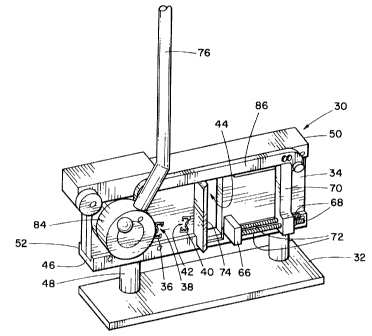
As shown in Figs 1 to 7 the trimming apparatus is shown generally as (30). It
has a base (32) which is , in this case a flat metal plate. It can be mounted
on a
bench or counter top in a suitable workplace location in a store.
A blind support plate (34) is attached on base (32 ) and Pies in a generally
vertical plane extending upwardly therefrom . Support plate (34) has a head
rail
support opening (36) shaped to the profile of the head rail of the blind,
extending
transversely through support plate (34). Thus the head rail support opening is
in
the shape of a three-sided channel, having an open side (38 ) facing to the
right
in Figs 1 and 2.
A bottom rail support opening (40) extends through support plate (34) ,
adjacent to and spaced from the head rail support opening (36). In this case
it
has a shape corresponding to the shape of the bottom rail (20) , in the form
of a
11
CA 02433683 2003-08-06
three-sided channel having an open side (42) , which in this case faces to the
left
in Figs 1 and 2.
Thus the open sides of the openings (36) and (40) face one another, and
the two openings are located a convenient distance apart for reasons which
will
become apparent below.
Note that reference to left and right, are purely for the purpose of
explanation of the illustration, and are without limitation.
The bottom rail support opening (40) , is shaped to the profile of the
bottom rail , and located along an axis which lies generally horizontal, in
this
embodiment.
The head rail and bottom rail in this embodiment are of similar cross
section, and define generally three-sided channels.
The head rail support opening (36) and bottom rail support opening (40),
in this embodiment face one another, so that the open sides of their
respective
channels are directed towards one another.
A fabric panel opening (44) also extends through support plate (34)
Fabric panel opening (44) is a generally rectangul<~r opec~ing which is of
sufficient
dimension to receive the folds or pleats of the fabric panel.
On the tower edge of support plate (34) there is a lower guide bar (40 ) ,
secured by screws, bolts or the like and lying on the base plate (32 ).
Alternatively columns (4~ ) can be mounted on base plate (32 ) and lower guide
bar (46 ) can be mounted on their upper ends. On the upper edge of support
plate (34) there is an upper guide bar(50 ), secured by screws, bolts or the
like.
12
CA 02433683 2003-08-06
Lower and upper guide bars (46 ) and (50 ) define lower and upper guide
channels(52) and (54) facing one another and aligned with one another.
In order to cut the head rail and bottom rail, a rail shear plate member (56)
is
slidably received in guide channels (52) and (54) . shear plate member (56) is
formed with, or has mounted thereon, a head rail cutting die (58) located in
registration with head rail support opening (36) in support plate (34) . A
bottom
rail cutting die (60) is formed in or mounted on shear plate member (56)
spaced
from the head rail cutting die (58), and registers ~nrith bottom rail support
opening
(40) in support plate (34).
Head rail die (58) and bottom rail die (60) define open sided channel
shapes corresponding to the head rail opening (36) and the bottom rail support
opening (40), with their open sides facing one another. The rail shear plate
member (56) is moveable along a rail shearing path of sufficient length to
sever
the thickness of the metal forming the head rail and bottom rail.
In order to cut the fabric panel, a fabric cutter blade (62) is provided,
mounted in
this case on a cutter plate or frame (64). Frame (64) is slidably supported in
lower and upper guide channels (52) and (54). Frame (64) carrying blade
(62), is moveable in registration with fabric opening (44) in support plate
(34).
Blade (62) is moveable along a movement path, or panel cutting path sufficient
to
traverse opening (44) thereby ensuring a complete cut of the fabric extending
there through.
Thus the shearing path of the rail shear plate (56) is relatively short,
whereas the cutting path of fabric cutting blade (62:) is considerably longer.
13
CA 02433683 2003-08-06
In order to hold the fabric in fabric support opening (44) while it is being
cut, a
clamp (66) is provided. Clamp (66) is mounted on two rods (68) which are
slidably held on bar (70). Springs (72) are provided around rods (68) and
normally urge the clamp (66) into its extended position. During the fabric
cutting
stroke, the clamp (66) engages the fabric in fabric support
opening (44) and squeezes it against a stop (74), thus holding it securely for
accurate cutting.
Movement of both the rail cutting plate (56) and the cutter frame (64) is
achieved, in this embodiment, through a single manually operated lever (76).
Other forms of movement means could be provided, including a screw drive
system, or power cylinders, such as hydraulic cylinders, none of which are
illustrated and are believed to be within the competence of those skilled in
the
a rt.
Lever (76) is rotatably mounted on a drive shaft (78) extending through
support plate (34). An eccentric cam roller (80) is mounted on shaft (76)
and is received in a drive recess (82) in rail shear plate (56). Semi-rotary
movement of lever (76) will cause rotation of drive shaft (78) will thus cause
rotary movement of cam roller (80). Roller (80) engages the edges of the rail
shear plate within recess (82) , and will thus cause rail shear plate (56) to
move
along its rail shearing path.
Movement of cutter frame (64) carrying fabric cutter blade (62) is achieved
by an eccentric boss (84 ) mounted on shaft (78), <~nd a connecting link (86)
extending from the periphery of boss (84) to frame plate (64).
14
CA 02433683 2003-08-06
Movement of cutter frame (64) will also commence as the lever (76)
makes a semi-rotary power stroke and will completely traverse the fabric
support
opening (44) in a single stroke, in this embodiment . It ~rvill also cause
movement
of clamp (66) so as to squeeze and hold the fabric against the stop (74)
within
support opening (44) during cutting of the fabric.
Link (86) is connected to plate (64) by a transverse transmission block
(88). Block (88) is located within a transmission opening (90) in support
plate
(34) Fig 7 and 8, and is bolted to bar (72) beneath link (86) on the one side
of
support plate (34) and is bolted to the frame plate (64) e~n the ohter side of
support plate(34). Opening ( 90) is oversize relative to block (88) and is
thus
large enough to permit movement of block (88) along the full length of the
cutting
stroke of frame plate (64).
In operation assuming it is intended to trim a fabric blind having both a
head rail (12) and a bottom rail (20), and a single panel e~f pleated fabric
(14) the
operator begins by moving or sliding the head rail (12) , and the bottom rail
(20)
so that one end of each extends part way to one side of the fabric panel (14),
and
thus extend away from one side edge of the fabric; panel (14) .The ends of the
head rail and bottom rail selected for trimming will be the ends which are
remote
from the cord controls (18) . The two rails are readily movable or slidable
partially endwise relative to the fabric panel (14) and this presents no
difficulty.
The ends of the head rail and bottom rail are then inserted into their
respective
support openings (36) and (40) in support plate (34).
'I 5
CA 02433683 2003-08-06
The head rail and bottom rail have their open sides facing each other.
This is matched by the orientation of their respective support openings (36)
and
(40), and thus ensures convenient operation for cutting both rails
simultaneously.
They will be extended through die openings (58) and (60) . The length of the
amount of each rail to be trimmed will correspond to the total trim required
for
that blind. At this stage the fabric panel (14) is not inserted into its
support
opening (44).
The lever (74) is then operated so as to move rail shear plate (56) . The
shear plate (56) moves tllrough a short shearing path equivalent to the
thickness
of the metal. This will require considerable force. Consequently the apparatus
provides a great degree of leverage in the transmission from the lever (76) to
the
shear plate (56) , to enable this to be done manually. This will sever both
the
head rail (12) and the bottom rail (20) . The two rails are then withdrawn
from
their openings (36) and (40 ) . With the two rails still partially extended
from the
one edge of the fabric panel (14) the opposite edge of the fabric panel (14)
will
then be bunched into its pleats and inserted into the fabric opening (44) in
support plate (34) . The edge of the fabric panel (14) will be extended beyond
blade (62) by a distance equal to one half the trim cut required. It will be
understood that when in this position that side edge of the fabric panel does
not
contain either the head rail or the bottom rail . These twa rails have already
been
trimmed by an amount equal to the total desired trim cut, and in this position
their
ends are located inwardly of the side edge of the fabric panel being trimmed..
16
CA 02433683 2003-08-06
Lever (74) is then operated moving blade (62 ) arid thus cutting the first
edge of
the fabric panel (14). The movement path of the blade (62 ) for cutting the
fabric is considerable longer than that required for moving the rail shear
plate for
shearing the head rail and bottom rail, but the force required is much less.
The
transmission provides therefor a lesser degree of leverage, but a greater
length
of movement of the cutting blade (62) . The same lever movement will also have
moved clamp (66) so as to squeeze and hold the fabric panel (14) securely
against stop (74) within opening (44) during cutting.
The fabric panel (14} is then withdrawn frorn opening (44) . The head rail
(12) and bottom rail (20) are then moved , or in this case slid, relative to
the
fabric panel (14) so that they extend from the first side edge of the fabric
panel
which has now been trimmed. The second side edge of the fabric panel (14) is
then inserted into fabric panel support opening (44) and extended beyond blade
(62) by an amount corresponding to the rest of the total trim cut. Lever (76)
is
again operated, thus moving blade (62) . This will then trim the second edge
of
the fabric panel (14).
Then head rail (12) and bottom rail (20),at tllis point, have a length equal
to the reduced width of the fabric panel. The rails can then be moved axially
back relative to the fabric panel (14) and the blind is then ready for
delivery to the
customer.
By cutting in three steps, the head rail and the bottom rail are cut , at one
end, remote from the controls (18 ) , by an amount or length equal to the
total
length of the trim cut. The fabric panel (14) is cut , down each side edge, by
'! 7
CA 02433683 2003-08-06
amounts equal to one half of the trim cut, on each side edge. The end result
is a
fabric blind in which the head rail and bottom rail and the fabric panel are
all
trimmed to the desired width, but in which the fabric panel remains
symmetrical
relative to the cords (16), down both side edges.
The foregoing is a description of a preferred embodiment of the invention
which is given here by way of example only. The invention is not t~ be taken
as
limited to any of the specific features as describedy but comprehends all such
variations thereof as come within the scope of the appended claims.
18