Note: Descriptions are shown in the official language in which they were submitted.
CA 02433697 2003-06-27
VIBRATIION-RESISTANT MOUNTING BRACKET FOIL HEAT EXCHANGERS
FIELD OF THE INVENTION
The present invention relates to the field of heat exchangers,
and more particularly, to mounting brackets for heat exchanger
cores.
BACKGROUND OF THE INVENTION
Heat exchanger cores are commonly formed from a plurality of
thin, substantially flat tubes, stacked upon one another in
spaced relation, which extend between a pair of spaced-apart
manifolds. The manifolds are often simply constructed from
pipe, suitably perforated to receive the flat tubes.
Exemplary of this construction is the heat exchanger described
in United States Patent No. 5,183,103 (Tokutake), issued
February 2, 1993.
For the purpose of mounting, i.e., within. the engine
compartment of a vehicle or the like, heat exchanger cores of
the type comprising perforated pipe manifolds, it is known to
braze a mounting bracket to the manifold:. The mounting
bracket usually includes a tab or flange adapted to be secured
to the vehicle frame. Usually, the mounting bracket is
provided with a portion which is capable: of resiliently
engaging the exterior of the manifold to keep the mounting
bracket in place during th.e brazing process, so as to avoid
the need for auxiliary clamping tools, which can add to cost
and can absorb heat in a brazing oven, resulting in poor
quality brazed joints. The mounting brackets taught in United
1
CA 02433697 2003-06-27
States Patent No. 5,069,275 (Suzuki et a:~.), issued December
3, 1991, are exemplary of this construction.
A difficulty with the pipe manifold type of heat exchanger
cores, however, is that the pipe manifolds have to be made
quite strong to support the mounting brackets, so this makes
them heavy and expensive to manufacture.
Another type of heat exchanger cores uses plate pairs to
define the heat exchanger passages. The plates are formed of
back-to-back dish-shaped plates, each plate b.aving a central
portion, a pair of spaced-apart bosses and a peripheral
flange. The plates thus disposed in pairs have the peripheral
flanges of each plate in the pair connected to one another to
form a fluid passage between the central portions, and the
plate pairs are disposed in stacked relation, with the bosses
in adjacent pairs having through holes therein, so that when
the bosses are joined to one another, they form a manifold to
permit the flow of fluid through the pairs. Exemplary of this
construction is the heat exchanger core described in United
States Patent No. 5,964,282 (Seller et a.l.), issued October
12, 1999.
Characteristic of the plate pair type of heat exchanger cores
used in the past is that special heavier gauge plates are
usually required to be joined to the fluid carrying plate
pairs in order to permit suitable mounting brackets to be
attached to the cores. This again increases the number of
components required and thus the cost of the heat exchangers.
2
CA 02433697 2003-06-27
SUMMARY OF THE INVENTION
In the present invention, a mounting bracket is provided for a
heat exchanger core having tubular or plate pair heat
exchanger passages, where the tubes or plate pairs have
peripheral edges or flanges adjacent to the manifolds. The
mounting bracket attaches directly to the peripheral edges or
flanges, giving maximum flexibility as t~a the location of the
mounting brackets.
According to the invention, there is provided a mounting
bracket for a heat exchange core of the type having a tubular
manifold disposed about a primary axis. The manifold is
formed with a plurality of tubular manifold segments and has
top and bottom ends spaced apart in the direction of a primary
axis. Inner and outer sides of the manifold are spaced apart
in the direction of a secondary axis perpendicular to the
primary axis. Front and back sides of t:he manifold are
spaced apart in the direction of a tertiary axis perpendicular
to the primary and secondary axes. A plurality of fluid tubes
are arranged in substantially parallel, spaced-apart relation.
Each tube extends inwardly from a respective manifold segment
and extends therefrom substantially parallel to the secondary
axis. Each tube has a respective peripheral flange with front
and rear portions adjacent to the respective front and back
sides of each respective manifold segment. Each flange has a
pair of laterally extending front and back edge portions
spaced-apart from one another in the direction of the tertiary
axis. The mounting bracket comprises a first clip portion
having a respective elongate groove formed therein adapted to
receive the front edge portion of a selected flange. A pair
3
CA 02433697 2003-06-27
of second clip portions each has a respective elongate groove
formed therein. The second clip portions are adapted to
receive, respectively, the back edge portion of an other of
the flanges disposed above the selected flange, and the back
edge portion of a further of the flanges disposed below
selected flange. The second clip portions are rigidly
connected to the first clip portion to grip, in combination
therewith, the core.
Preferably, the first clip portion is shaped and dimensioned
such that the effective depth of the elongate groove therein
decreases, most preferably to nil, as the first clip portion
extends laterally inwardly.
Preferably, each of the second clip portions is shaped and
dimensioned such that the effective depth of the elongate
grooves therein decreases, most preferably to nil, as the
second clip portions extend laterally inwardly.
Preferably, the other flange is adjacent to the selected
flange and the further flange is longitudinally adjacent to
the selected flange.
Preferably, the mounting bracket further comprises a mounting
panel portion rigidly connected to the first clip portion and
adapted to be secured to a vehicle frame, in use.
Preferably, the mounting panel portion projects laterally
beyond the outer edge of the selected flange in use.
4
CA 02433697 2003-06-27
Preferably, the first clip portion and t:he panel portion
together define an elongate bridge structure, each defining
one end thereof, and the elongate groove of the first clip
portion runs longitudinally relative to the bridge structure,
and terminates at the end defined by the first clip portion.
The pair of second clip portions are preferably rigidly
connected to the first clip portion by a pair' of leg portions,
disposed in spaced-apart relation to one another, each leg
portion rigidly extending between the bridge structure and a
respective second clip portion.
The leg portions are preferably substantially planar, are
orientated substantially parallel to one another, and have
contacting parts which are disposed, in use, in overlapping
relation, respectively, against the bottom or top surface of
the other flange and against the top or :bottom surface of the
further flange.
The second clip portions each preferably extend generally the
length of the bridge structure and slightly beyond the first
clip portion thereof.
The mounting bracket preferably :further comprises a pair of
abutment ear portions extending away from one another, each
from a respective leg portion and in substantially transverse
relation thereto, and abutting, in use, respectively, the
outer edges of each of the other and further flanges.
In use, the second clip portions preferably extend laterally,
inwardly, beyond the lateral extent of t:he manifold and the
5
CA 02433697 2003-06-27
first clip portion terminates adjacent to the mid point of the
manifold.
BRIEF DESCRIPTION OF THE DRAWINGS
In the accompanying drawings, which are :Eor the purpose of
illustration and description only, and are not intended as a
definition of the limits of the _inventio~a:
Figure 1 is a perspective view of a mounting bracket
according to a preferred embodiment of the present invention;
Figure 2 is a top plan view of the mounting bracket of Figure
1;
Figure 3 is a right side elevational view of the mounting
bracket of Figure l;
Figure 4 is a front elevational view of the mounting bracket
of Figure 1;
Figure 5 is a bottom view of the mounting bracket of Figure
1;
Figure 6 is a left side elevational view of the mounting
bracket of Figure 1;
Figure 7 is a rear elevational view of the mounting bracket
of Figure l;
6
CA 02433697 2003-06-27
Figure 8 is an enlarged perspective view of the mounting
bracket of Figure 1;
Figure 9 is an exploded view of the mounting bracket of
Figure l, shown at a position laterally outwardly from a heat
exchanger core, only a portion of which :i_s sh.own;
Figure 10 is a view similar to Figure 9, with the mounting
bracket shown in use with the heat excha:riger core;
Figure 11 is an enlarged view of enoircl~~d area 11 in Figure
10;
Figure 12 is a front elevational view of the structure of
Figure 11;
Figure 13 is a view taken along section lines 13-13 of Figure
12;
Figure 14 is a view taken along section lines 14-14 of Figure
12;
Figure 15 is a view taken along section lines 15-15 of Figure
12; and
Figure 16 is a perspective view similar to Figure 8, but
showing another preferred embodiment of the subject invention.
7
CA 02433697 2003-06-27
DESCRIPTION OF THE PREFERRED EMBODIMENT
A mounting bracket according to a preferred embodiment of the
present invention is illustrated, inter alia, in Figure 1
through Figure 8, and is designated with general reference
numeral 20.
The mounting bracket 20 will be described with particularity
in following paragraphs.
However, for greater clarity in the following description, a
heat exchanger core, which does .not form part of the
invention, but rather, is for use with which the mounting
bracket 20, will be firstly described with general reference
to Figure 9, wherein it is designated with general reference
numeral 22.
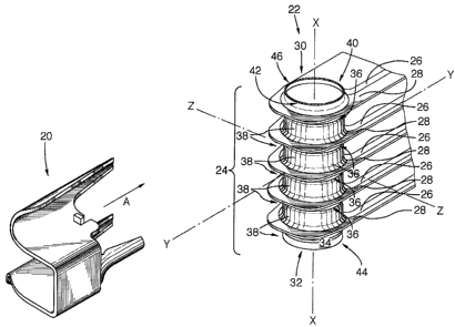
In this regard, the heat exchanger core 22, only a part of
which is shown for ease of illustration, includes a manifold
24 having a primary axis X-X.
The primary axis X-X is a longitudinal axis for manifold 24.
Core 22 also has a secondary or lateral axis Y-Y arranged
substantially transverse to the primary axis X-X to intersect
same. A plurality of fluid tubes 26 extend parallel to
lateral axis Y-Y. Tubes 26 are formed of plate pairs and thus
have joined peripheral flanges 28.
Core 22 also as a tertiary axis 2-2 arranged substantially
transverse to and intersecting each of the primary and
secondary axes X-X and Y-Y.
8
CA 02433697 2003-06-27
The manifold 24 is formed by mating, communicating end bosses
formed in the plate pairs, and thus is generally tubular in
configuration having front side 44 and a back. side 46 and an
inner side 40 and an outer side 42. The outer surface 34 can
be considered as having a plurality of grooves 36 formed
therein between the joined peripheral fl<~nges of the plate
pairs. The grooves 36 are substantially uniformly
longitudinally spaced-apart from one another and each is
concentric with the primary axis X-X. The manifold 24. is thus
divided into a plurality of tubular manifold segments 38. The
top and bottom ends 30, 32 are spaced apart from one another
in the direction of the primary axis X-X. The front and back
manifold sides 44, 46 are spaced apart from one another in the
direction of the tertiary axis Z-2. The inner and outer
manifold sides 40, 42 are spaced apart from one another in the
direction of the secondary axis Y-Y.
The plurality of fluid tubes 2& are arranged in substantially
parallel, spaced-apart relation. Each tube 26 is associated
with a respective manifold segment 38 and extends inwardly
from the inner side 40 of one manifold 24 to another manifold
24 (not shown) at the opposite end of heat exchanger core 22.
The tubes 26 are substantially parallel to the secondary axis
Y-Y.
With general reference to Figures g-11, each flange 28 extends
radially, with respect to the primary axis X-X, from its
respective manifold segment 38. Further, each flange 28 at
least partially surrounds its manifold s~~gmerlt 38. Each
flange 28 has a top surface 48 and a bottom surface 50 and is
9
CA 02433697 2003-06-27
circumscribed by an outer edge portion 5.2, disposed laterally
outwardly from the manifold 24, and by a pair of laterally-
extending front and back edge portions 54, 56 spaced-apart
from one another in the direction of the tertiary axis Z-Z.
Against this background, the mounting bracket 20 of the
preferred embodiment will now be described and should be
understood to comprise a first clip portion 58 and a mounting
panel or lug portion 60, as illustrated, inter alia, in Figure
IO 8.
The first clip portion 58 has an elongate groove 62 (see
Figure 3) formed therein.
The mounting panel portion 60 is rigidly connected to the
first clip portion 58 in a manner such that first clip portion
58 and panel portion 60 together define an elongate bridge
structure 68 having opposite ends 68A,68B. The elongate
groove 62 of the first clip portion 58 runs longitudinally
relative to the bridge structure 68, and terminates at the end
68A thereof defined by the first clip portion 58.
The mounting bracket 20 further comprises a pair of second
clip portions 72 and a pair of leg portions 70.
Each of the second clip portions 72 has a respective elongate
groove 64 formed therein, and extends longitudinally slightly
beyond the first clip portion 58 thereof, as best illustrated
in Figures 2 and 4.
10
CA 02433697 2003-06-27
The leg portions 70 each extend between the bridge structure
68 and a respective second clip portion '72, thereby to connect
the second clip portions 72 and t:he first clip portion 58, and
will be seen to be substantially planar, disposed in spaced-
apart, substantially parallel relation to one another, and to
have respective edge areas 70A.
Also provided is a pair of abutment ear portions 74, extending
away from one another, each from a respective leg portion 70
and in substantially transverse _relation thereto.
In the preferred embodiment, the mounting bracket 20 is
intended to be permanently connected to the heat exchanger
core 22 by brazing. As such, mounting bracket 20 is
constructed out of a suitable brazing material, specifically,
brazing-clad aluminum, suitably stamped and formed into shape,
so that close-fitting, abutting and overlapping structures on
the mounting bracket 20 and heat exchanger care 22 wi=Ll be
brazed together, preferably in the same process by which the
heat exchanger core 22 is brazed in a furnace brazing process.
Mounting bracket 20 can be made of other metals however, and
suitably joined to core 22. The configuration of brazing-clad
aluminum, and the manner in which the various structural
features of the mounting bracket 20 of the preferred
embodiment may be formed are well known to persons of ordinary
skill in the art, and as such, not detailed herein.
In use, the mounting bracket 20 is positioned against the heat
exchanger core 22 at an assembly position, shown in Figure 20
through Figure 15, by positioning the mounting bracket 20
l~
CA 02433697 2003-06-27
laterally outwardly from the core 22, as shown in Figure 9,
and urging same in the direction of arrow A thereof.
At the assembly position of mounting bracket 20 as seen in
Figure I1, the second clip portions 72 extend. laterally,
inwardly, slightly beyond manifold 24, a:nd th.e first clip
portion 58 terminates proximate the lateral midpoint of
manifold 24 as indicated in Figure 12. 'rhe elongate groove 62
of the first clip portion 58 is in close-fitting receipt of a
selected flange 28', as shown .in Figure 15. It will be
evident that the groove 62 thus defines means for mechanically
engaging, in use, the selected f:Lange 28'. It is notable, for
reasons discussed below, that the first clip portion 58 is
tapered or shaped and dimensioned such that the effective
depth of the elongate groove 62 decreases to nil as the first
clip portion 58 extends laterally inwardly, as best indicated
in Figures 2 and 5.
The elongate grooves 64 of the second clip pardons 72 are in
close-fitting receipt, respectively, of an other flange 28"
disposed, with respect to the selected flange 28°, above or
relatively proximal to the top e_~d 30 of manifold 24, and of a
further flange 28" ' disposed, with respect to the selected
flange 28', below or relatively distal to the top end of the
manifold 24, as illustrated in Figures 11,13,14,15. Thus,
grooves 64 of the second clip portions 72 define means for
mechanically engaging, respectively, each. of the other flange
2 8 " and the further flange 28 " ' .
It is notable, again for reasons discussed in following
paragraphs, that each of the second clip portions 72 is
12
CA 02433697 2003-06-27
tapered or shaped and dimensioned such that the effective
depth of the elongate groove 64 therein decreases to nil as
the second clip portions 72 extend laterally inwardly.
The contacting parts 70A (see Figure 8) are disposed, in
overlapping relation, respectively, against the bottom surface
50 of the other flange 28'° and against the t.op surface 48 of
the further flange 28" ', as indicated in Figures 13,14,
wherein the flanges 28" , 28" ' are delineated in chain-dotted
lines. The abutment ear portions 74 engage respectively, the
outer edges or edge portions 52 of each of the other flange
28'° and the further flange 28°" , as indicated in Figures
11,12. The mounting panel portion 60 projects laterally
beyond the outer edge 52 of the selected flange 28', as
indicated in Figure 12, wherein the selected flange 28' is
shown in chain-dotted outline, thereby to facilitate mounting
of the heat exchanger core 22.
In such assembly position, the mounting bracket 20 grippingly
engages the core 22 with sufficient tenacity so as to permit
subsequent permanent connection therebetween by conventional
techniques such as brazing, soldering, welding, adhesives or
the like, without the need for auxiliary clamps. This is
advantageous, since auxiliary clamps carp add to cost and, in
the context of brazing, can absorb heat, resulting in poor
quality brazed joints.
It will be evident that after such permanent connection has
been completed, the mounting bracket 20 and the heat exchanger
core 22 will form an integral unit suitable for mounting to a
vehicle frame (not shown). Consequently, motion of the
13
CA 02433697 2003-06-27
vehicle may cause vibration of the heat exchanger core 20 with
respect to the vehicle frame. The aforementioned tapering of
the first clip portion 58 and second cli=p portions 72
distributes and absorbs any transverse stresses on the heat
exchanger core to reduce the likelihood of cracking of the
core.
However, the tapering of first and second clip portions 58 and
72 is not essential. Figure 16 shows another preferred
embodiment where clip portion 58' and 72' are not tapered.
Otherwise the mounting bracket of Figure 16 ~_s the same as the
brackets shown in Figures 1 to 15.
Having described preferred embodiments of the mounting bracket
of the present invention, it will be evident that various
modifications and alterations can be made to the structure as
described.
For example, whereas in the preferred embodiments illustrated,
the mounting bracket engages the flanges of three contiguous
manifold segments, to wit, the selected flange 28', the other
flange 28'° which is longitudinally adjacent to the selected
flange 28' and the further flange 28" ' which is
longitudinally adjacent to the selected flange 28', the
mounting bracket could of course: be readily resized, such that
it spans more flanges or few flanges, if. desired (not shown).
Further, mounting bracket 20 coL~ld be made a bit wider than
shown, so that edge areas 70A engage the top and bottom
surfaces of the respective flanges 28" and 28°'°, or both
bottom surfaces or both tap surfaces. In these instances, ear
portions 74 could be orientated differently, such as toward
14
CA 02433697 2003-06-27
each other or in the same direction, as long as at least one
of them abuts flange edge portion 52.
As well, whereas in the preferred embodiment the first clip
portion and second clip portions are elongate structures of
substantially U-shaped profile, it will readily understood
that such construction is not necessary; for example, the
elongate grooves could be C-shaped. Clip portions 58 and 72
can be different lengths. The grooves in the clip portions
could be formed in other ways, such as by us~_ng projections or
flanges that group the peripheral edges of the tubes of the
heat exchanger core.
Moreover, whereas the preferred mounting bracket is
constructed out of brazing clad aluminum, for reasons outlined
previously, it will of course be evident than other metals or
materials may be readily substituted therefor, and the
invention is considered to encompass mounting brackets
constructed from other materials.
Additionally, whereas in the illustrations, clearance is shown
between the fluid tubes, it will be evident that the mounting
bracket may be utilized with heat exchangers having fins or
vanes disposed between the tubes.
The terms "tube" or "tubular" ire the pre=sent specification is
intended to include any configuration of hollow conduit, such
as conduits having rectangular or hexagonal cross-sections,
for example.
15
CA 02433697 2003-06-27
As well, whereas the abutment ear portions in the preferred
embodiments abut the flange outer end portions in use, they
could readily be omitted, and if desired, the positioning and
functionality thereof could be easily assumed by the
contacting parts that abut the manifold.
Of course, and without limitation, the mounting panel portion
could be formed with an aperture shaped and dimensioned to
receive a suitable mechanical fastener such as a nut and bolt
assembly or rivet (not shown), to mount the heat exchanger
core.
While the preferred embodiments show plate pair type heat
exchanger cores, the mounting bracket of the present invention
could be used with the heat exchanger cores having pipe
manifolds and heat transfer tubes having peripheral edges or
flanges adjacent to the front and back sides of the manifolds,
or surrounding the manifolds.
Additionally, the mounting bracket may be utilized with heat
exchangers having turbulizers, of expanded metal or the like,
disposed within the fluid tubes.
Further, whereas the mounting panel portion illustrated is
substantially planar, and orientated substantially normal to
the tertiary axis in use, it could be orientated in any other
direction, even perpendicular to the tube sides (i.e. normal
to the secondary axis) if desired, to su~_t a particular
mounting configuration for the core.
16
CA 02433697 2003-06-27
Yet further, whereas the disclosure is directed primarily to
the field of heat exchangers, the mounting bz-acket of the
present invention may be used in association with other fluid
handling devices of similar construction, for example,
condensers, filtration devices, fuel cells and fuel reformers
or processors.
As well, whereas the longitudinal axis defines a manifold top
and bottom end which, in the preferred embods_ments
illustrated, are spaced apart from one another vertically, it
will be evident that the manifold "top" need not be disposed
upwardly from the manifold "bottom" and could., for example, be
disposed horizontally therefrom, or even downwardly therefrom.
From the foregoing, it will be evident to persons of ordinary
Skill in the art that the scope of the present invention is
limited only by the accompanying claims, purposively
construed.
17