Note: Descriptions are shown in the official language in which they were submitted.
CA 02434424 2010-08-18
1
RECORDING APPARATUS, METHOD AND MEDIUM
BACKGROUND OF THE INVENTION
1. Field of the Invention
The present invention relates generally to a readable/writable data
recording medium, and relates more particularly to a data recording medium for
recording multimedia data containing data in different formats, including
video
data, still image data, and audio data. The invention also relates to an
apparatus and a method for recording information to this data recording medium
or for reproducing the recorded information.
2. Description of Related Art
In addition to recording and storing computer data, read-only
optical disc media such as DVD-ROM (Digital Versatile Disc-ROM) discs are
today also used as a recording medium for movies and other video information,
photographs and other still images, and audio data (referred to herein as
multimedia or AV data). DVD-RAM discs, a randomly writable, phase-change
type optical disc medium, with a multiple gigabyte capacity have also become
available.
Widespread adoption of MPEG standards, particularly MPEG-2, a
group of international coding standards for digital AV data, have made DVD-
RAM media well-suited as a recording and playback medium for use in the AV
field as well as for storing computer data. More specifically, DVD-RAM discs
are
CA 02434424 2003-07-11
2
widely expected to replace conventional magnetic tape as the medium of choice
for AV recording and playback.
Subjects of particular interest for the future include how AV data
can be recorded to provide new functions and performance greatly surpassing
that of conventional AV equipment using new high capacity optical disc media.
The greatest benefit of using disc media is a significant
improvement in random access performance compared with magnetic tape.
While it is possible to randomly access magnetic tape, it takes on the order
of
several minutes to rewind the tape. This is a significant order of magnitude
greater than the seek time (several 10 ms) of optical disc media. For most
practical purposes, tape is therefore not suitable as a random-access
recording
medium. A further benefit of the random access performance of optical disc
media is that distributed recording of AV data, which is impossible with
conventional tape, is possible with optical discs.
Fig. 1 is a block diagram of a DVD recorder (DVD drive device).
As shown in Fig. 1 this drive device has an optical pickup 11 for reading data
from a DVD-RAM disc 10, an ECC (error correcting code) processor 12, a one
track buffer 13, a switch 14 for directing input to and output from the track
buffer
13, an encoder 15, and a decoder 16.
As shown in Fig. 1 data is recorded to a DVD-RAM disc 10 in
sector units (1 sector = 2 KB). In addition, 16 sectors form one ECC block for
error correction processing by the ECC processor 12.
The track buffer 13 is used for recording AV data at a variable
bitrate in order to record AV data more efficiently to the DVD-RAM disc 10.
More specifically, while the DVD-RAM disc 100 read rate (Va) is a fixed
bitrate,
CA 02434424 2003-07-11
3
the AV data has a variable bitrate (Vb) determined primarily by the complexity
of
the data content (images in the case of video). The track buffer 13 is used to
absorb the difference between Va and Vb. The track buffer 13 is also used even
more effectively to continuously supply AV data to the decoder 16 when the AV
data is located non-contiguously on the DVD-RAM disc 10. The track buffer 13
is also used to record AV data sent from the encoder 15 to the DVD-RAM disc
10.
The Universal Disc Format (UDF) file system is used with DVD-
RAM discs in order to use high capacity DVD-RAM recording media more
effectively and enable disc content to be accessed with a personal computer.
The UDF file system is described in detail in the Universal Disc Format
Standard.
A conventional AV system is described next. Fig. 2 shows typical
conventional AV equipment, media types, and data formats. For example, to
view content on a video tape the user normally inserts a video cassette into a
VCR and watches it on a television. To listen to music, the user might insert
a
CD into a CD player or a CD/radio/cassette player and use speakers or
headphones to listen. In other words, conventional AV equipment has used
different media for different content formats (video and audio). This has
meant
that the user must constantly change the media or AV equipment according to
the desired type of content, and this is inconvenient.
Advances in digital technologies have also led to rapid acceptance
of DVD video discs for distributing packaged software and digital broadcast
satellites for transmitting program content. Both of these were made possible
by
CA 02434424 2003-07-11
4
the revolution in digital technology and particularly by the adoption of the
MPEG
standard.
Fig. 3 shows the MPEG stream used for DVD video discs and
digital broadcasting.
As shown in Fig. 3 the MPEG standard defines a hierarchical
structure. What is important to note here is that the MPEG System layer stream
that is ultimately used by the application is different for package media such
as
DVD video discs and communication media such as digital broadcasting.
The former is called the MPEG Program Stream, and transfers
data in pack units generated according to the sector recording unit used with
DVD video discs (2048 bytes). The latter is called the MPEG Transport Stream,
and transfers data in Transport Stream (TS) packet units of 188 bytes for ATM
transmission.
It was expected that the combination of digital technology and
MPEG coding technologies for audio and video would enable AV data to be
handled freely independently of any specific transmission medium, but small
differences such as described above have combined to prevent the emergence
to date of AV equipment and media compatible with both package media and
communication media. The introduction of high capacity optical disc media such
as DVD-RAM is expected to eliminate the inconvenience incumbent with
conventional AV equipment as noted above.
In particular, optical discs capable of recording the MPEG
Transport Stream in the same way as the MPEG Program Stream are expected
to emerge with the start of digital satellite broadcasting.
CA 02434424 2003-07-11
The ideal DVD recorder would be able to freely reproduce and
present a variety of content formats from a single medium using a single AV
device as shown in Fig. 4 without the user being aware of the format. More
specifically, Fig. 5 shows an example of a menu displayed with this ideal DVD
5 recorder. This menu is presented on a television screen and enables the user
to
select "1) Movie Theater" from a digital satellite broadcast, "2) Morning Soap
Opera" or "3) World Cup Soccer" from a conventional terrestrial broadcast, or
"4) Beethoven" from a CD without the user being aware of the recording format
or the medium from which the content is available or recorded.
The greatest problem achieving this ideal DVD recorder using a
type of optical disc expected to be used as the next-generation AV recording
medium is how to uniformly manage AV data and AV streams in different
formats. No special management technique is needed to manage only formats
that are already used. However, if the ideal DVD recorded described above is
to
be realized it is essential to use a method that is compatible not only with
the
numerous formats already in use but can also adaptively handle various new
formats that will surely appear in the coming years.
The inconvenience caused by the prior art as described above,
that is, the need for the user to operate the AV system with an awareness of
the
content and format, can occur as a result of differences in the user interface
resulting from whether or not different AV streams can be handled uniformly. A
problem for handling a variety of AV streams is therefore how data digitized
on
the transmission side (such as for digital broadcasting) is handled on the
reception side. In particular, in order to use functions in new digital
satellite
broadcasting programs after the program content has been recorded to local
CA 02434424 2010-08-18
6
media, that is, in order to enable time-shift recording, the content stream
must
be recorded in the same condition in which it was transmitted. The MPEG
Transport Stream, for example, enables multiple video streams to be displayed
at the same time (using the so-called multiview function).
In addition, the ability to time-shift record programs from new
digital broadcasting services expected to begin in the future is also
desirable
even if part of the service content is still unknown.
The entry point is one example of utilizing the random accessibility
that is the greatest feature of disc media with digitally recorded AV data.
The
need for the user to be able to set an entry point at a desired location so
that
this user-defined entry point can be accessed to start playback from that
point is
increasing. The recording device, however, also automatically sets other entry
points. Confusion results from these different entry points being mixed, and a
data structure enabling user-defined entry points to be identified from entry
points set by the recorder is therefore needed.
SUMMARY OF THE INVENTION
An object of the present invention is therefore to manage entry
points in a manner that is easy for the user to understand.
A further object is to enable the stream used for digital
broadcasting (for example, the MPEG Transport Stream) to be recorded
together with various AV streams, and to enable reproducing the recorded data.
CA 02434424 2010-08-18
6a
Certain exemplary embodiments can provide a recording
apparatus comprising: a receiver unit operable to receive a digital stream; an
input unit operable to receive a first entry point representing a start point
of
playback of the digital stream, from a user; an obtaining unit operable to
obtain a
second entry point representing a point where the attribute of the digital
stream
changes; and a control unit operable to, (i) generate playback path
information
representing a playback path of the digital stream, the playback path
information
containing the first entry point; (ii) generate object information managing
the
digital stream, the object information being different from the playback path
information and containing the second entry point; and (iii) record the
digital
stream, the object information and the playback path information to a
recording
medium.
Certain exemplary embodiments can provide a recording method
comprising: receiving a digital stream; receiving a first entry point
representing a
start point of playback of the digital stream, from a user; obtaining a second
entry
point representing a point where the attribute of the digital stream changes;
generating playback path information representing a playback path of the
digital
stream, the playback path information containing the first entry point;
generating
object information managing the digital stream, the object information being
different from the playback path information and containing the second entry
point; and recording the digital stream, the object information and the
playback
path information to a recording medium.
CA 02434424 2010-08-18
6b
Certain exemplary embodiments can provide a recording medium
which is recorded with: a digital stream; playback path information
representing a
playback path of the digital stream, the playback path information containing
a
first entry point, the first entry point representing a start point of
playback of the
digital stream; and object information managing the digital stream, the object
information being different from the playback path information and containing
a
second entry point, the second entry point representing a point where the
attribute of the digital stream changes.
A data recording apparatus according to other
embodiments has a reception unit for receiving a stream including encoded
digital data, an analyzing unit for detecting change in attributes of the
CA 02434424 2010-08-18
7
stream received by the reception unit and outputting the detected information,
a
control unit for acquiring the detected information output by the analyzing
unit
and time information for the time at which an attribute change was detected as
a first entry point and generating management information registering the
first
entry points, and a drive device for recording the management information
generated by the control unit and the stream received by the reception unit to
a
data recording medium. This data recording apparatus further comprises an
input unit for setting at least one second entry point in the playback path of
the
stream to enable accessing and reproducing the stream from a desired point.
The control unit produces the management information so that the first entry
points and second entry points can be discriminated from each other.
A data recording method according to further embodiments comprises
steps for performing the operations done the data recording apparatus of
various
embodiments.
The embodiments can also be achieved as a data recording program
executed by a computer to perform these same operations.
This data recording program can also be recorded to a data
recording medium.
The control unit can generate management information containing
a first table registering the first entry points, and a second table
registering the
second entry points.
The control unit could alternatively generate management
information having a first identification flag added to the first entry points
and a
different identification flag added to the second entry points.
CA 02434424 2003-07-11
8
Thus comprised, management information whereby entry points
set based on stream attributes and entry points set by the user can be
separately detected can be obtained by the present invention. Furthermore, by
selectively displaying the entry points based on the management information,
the user can easily find a desired scene from the displayed information.
Other objects and attainments together with a fuller understanding
of the invention will become apparent and appreciated by referring to the
following description and claims taken in conjunction with the accompanying
drawings.
BRIEF DESCRIPTION OF THE DRAWINGS
Fig. 1 is a block diagram of the drive device in a DVD recorder;
Fig. 2 shows the relationship between conventional AV equipment
and media;
Fig. 3 shows an MPEG Program Stream and MPEG Transport
Stream;
Fig. 4 shows the relationship between AV equipment and media
that is potentially possible with a DVD recorder;
Fig. 5 shows an example of a menu presented with a DVD
recorder;
Fig. 6A shows the relationship between an AV file and directory;
Fig. 6B is a conceptual diagram of disc address space;
Fig. 7 describes the relationship between objects, object
information, and PGC information;
CA 02434424 2003-07-11
9
Fig. 8 shows the stream management information derived from
the object information;
Fig. 9 shows the relationship between a digital broadcast object
(D_VOB), digital broadcast object information (D VOBI), and PGC information;
Fig. 10A to Fig. 10F describe a timing map according to the
present invention;
Fig. 11A and Fig. 11 B show the relationship between TS packets
and header information in a stream object (SOB);
Fig. 12 describes management information on a DVD-RAM disc;
Fig. 13 describes implementing a multiview function;
Fig. 14 describes entry points according to the present invention;
Fig. 15 describes the table of automatically set entry points and
the table of user-defined entry points;
Fig. 16 shows entry point tables provided for each of multiple
views;
Fig. 17 is a block diagram of a model player according to the
present invention;
Fig. 18 is a block diagram of a DVD recorder;
Fig. 19 is a flow chart showing the recording operation of the
recorder;
Fig. 20 describes an EIT for PG_Change detection;
Fig. 21 describes PSI/SI information for PSI/SI detection;
Fig. 22 describes an MPEG-2 stream for SQH_Change detection;
Fig. 23 describes DII for Data Top detection;
Fig. 24 describes DII for Data_Change detection;
CA 02434424 2003-07-11
Fig. 25 describes PMT for PMT Change detection;
Fig. 26 describes DII for DE_Change detection;
Fig. 27 describes DII for Module_Change detection;
Fig. 28 describes EIT for Aud_Change detection;
5 Fig. 29 describes EIT for Multi View detection;
Fig. 30 describes PMT, EIT for parental control information
detection;
Fig. 31 is a flow chart showing the playback operation of the
recorder;
10 Fig. 32 is a flow chart showing the process for setting user-defined
entry points; and
Fig. 33 is a flow chart showing the reproduction process for user-
defined entry points.
DESCRIPTION OF THE PREFERRED EMBODIMENTS
A data recording medium, recording apparatus, and playback
apparatus according to the present invention are described in detail below
using
by way of example a DVD-RAM disc, DVD recorder, and DVD player.
A DVD-RAM disc according to the present invention can record
AV data in various formats to a single disc and can uniformly manage the
recorded data. It is therefore possible to record on a single disc both video
data
recorded by encoding a conventional analog broadcast to an MPEG Transport
Stream, and the MPEG Transport Stream transmitted as a digital broadcast.
This data recorded to a DVD-RAM disc can also be reproduced according to a
specified procedure. A DVD-RAM disc according to the present invention
CA 02434424 2003-07-11
11
therefore contains management information for managing an AV stream
independently of the format of the AV data.
The data structure of data recorded to a DVD-RAM disc according
to the present invention is described next with reference to Fig. 6A and Fig.
6B.
The data structure of the DVD-RAM disc 100 recognizable through the file
system of the disc 100 is shown in Fig. 6A. The structure of physical sectors
on
the disc 100 is shown in Fig. 6B.
As shown in the figure the physical sectors start with a lead-in
area 31. A reference signal for stabilizing the servo and identification
signals for
identifying the specific media type are recorded in the lead-in area 31.
The data area 33 follows the lead-in area 31, and is used for
storing logically valid data. Management information for file system use is
recorded at the beginning of the data area 33. This management information is
known as the "volume information." The file system is typically written in the
UDF format, which is known from the literature. Further description thereof is
therefore omitted. The physical disc structure then ends with a lead-out area
35.
The same reference signal and other information recorded to the lead-in area
31 are recorded to the lead-out area 35.
The file system enables data on the disc 100 to be handled as a
directory and files as shown in Fig. 6A. As shown in Fig. 6A all data handled
by
the DVD recorder is managed in the DVD_RTAV directory directly under the
root directory.
A DVD recorder according to this embodiment of the invention can
handle two types of files: AV files containing audio/video data (AV data), and
management information files containing information for managing the AV files.
CA 02434424 2003-07-11
12
In the example shown in Fig. 6A, the management information file is
VIDEO_RT.IFO, and the AV files are the M VOB.VOB file containing moving
picture (video) data and the D VOB.VOB file containing video data for digital
broadcasting.
These files are described in detail below. Individual AV streams
are defined as objects in the present invention. That is, an object contains a
number of AV streams such as the MPEG Program Stream. By thus handling
AV streams as abstracted objects, AV stream management information can be
defined using a uniform object information model (Objectl).
The management information is described first below with
reference to Fig. 7. The AV file management information VIDEO_RT.IFO is
used by way of example as the management information. Fig. 7 shows the
relationship between AV file object, object information, and program chain
(PGC) information. The management information VIDEO_RT.IFO contains
object information Objectl 80 for managing object recording locations, PGC
information 50 and 70 defining the playback sequence and playback time of the
data to be reproduced from the data recorded to the DVD-RAM disc, and Video
Manager General Information VMGI 90. An AV stream has elements (such as
time attributes) that can be shared while having individual differences
according
to the format. This enables abstraction as noted above. In addition, AV
streams
of the same format are stored in the recorded sequence in the same AV file.
The object information Objectl 80 comprises general information
Object GI 80a relating to the object, object attribute information Attributel
80b,
an access map 80c for converting the object presentation time to a disc
address
value, and an entry point table 80d relating to the PGC information 50 and
CA 02434424 2003-07-11
13
defining the access points to desirable locations in the object (these access
points are referred to below as entry points).
The access map 80c is used for converting between a time axis
and data (bitstream) axis. The access map 80c contains data for each object
unit correlating the time domain and the address domain. This is because each
object is composed of multiple object units (VOBU) as further described below.
An access map 80c is needed because an AV stream generally has two
reference axes, a temporal axis and a data (bitstream) axis, and a perfect
correlation does not exist between these two references. For example, variable
bitrate coding whereby the bitrate is changed according to the complexity of
the
video content is increasingly common in MPEG-2 video, an international
standard for video stream coding. This means that a proportional relationship
does not exist between the presentation time and the amount of data from the
beginning of the content stream, and the stream therefore cannot be randomly
accessed referenced to the time base. An access map 80c is therefore needed
to define the correlation between time and data.
The PGC information 50, 70 is used to control reproducing the
video data and audio data, i.e., the objects, recorded to the DVD-RAM disc
100.
The PGC information 50, 70 define single units of data for continuous playback
by the DVD player. More specifically, the PGC information 50, 70 denotes the
cell information 60, 61, 62, 63 identifying the object to be reproduced and
what
part of the object is to be presented (the playback period). This cell
information
is described further below.
The PGC information includes original PGC information 50 and
user-defined PGC information 70. The original PGC information 50 is
CA 02434424 2003-07-11
14
automatically generated by the DVD recorder during object recording so as to
include all recorded objects. The user-defined PGC information 70 enables the
user to define a desired playback sequence.
The entry point table 80d of the object information Objectl 80
described above defines entry points relating only to the original PGC
information 50 (therefore also referred to below as "original entry points").
Entry
points related to the user-defined PGC information 70 (also called below "user-
defined entry points") are defined, for example, in the entry point table 72
included in the cell information 71. The original entry points are set
automatically by the DVD recorder in the objects defined in the object
information Object) 80. The user entry points are set by the user at desired
points in the object playback path.
It should be noted that the entry point table 80d could be written to
the original PGC information 50. If located in the original PGC information
50,
an entry point table 80d could be provided for each cell information entry, or
one
entry point table 80d could be provided in the original PGC information 50 as
information not included in each cell information entry.
The user entry point table included in the user-defined PGC
information 70 could likewise be written as a single table in the user-defined
PGC information 70 as information not contained in each cell information entry
rather than writing a user entry point table to each cell.
The structure and the function of the original PGC information 50
and the user-defined PGC information 70 are identical except that the user-
defined PGC information 70 is defined by a user and contains at least one user
CA 02434424 2003-07-11
entry point table 72. The original PGC information 50 is therefore described
in
detail below. Entry point tables 72 and 80d are described further below.
As shown in Fig. 7 the original PGC information 50 contains at
least one cell information block 60, 61, 62, or 63. The cell information 60
5 specifies the object to be presented and the playback period in that object.
The
PGC information 50 normally records multiple cells in a particular order. The
order of the cell information in the PGC information 50 denotes the playback
sequence when objects specified by each cell are reproduced.
Each cell information entry such as cell information 60 contains
10 type information (Type) 60a denoting the type of object specified by the
cell
information 60, object multiview information (View Type) 60b as further
described below, an object identifier (Object ID) 60c uniquely identifying the
object, the starting position (Start) 60d in the object on the time base, and
the
ending position (End) 603 in the object on the time base. During data playback
15 the cell information 60 is read sequentially from the PGC information 50
and the
objects specified by each cell are reproduced for the playback period
specified
by the cell.
The abstracted object information must be defined more
specifically in order to apply it to an actual AV stream. This is easier to
understand with reference to class inheritance in an object-oriented
programming model where the object information is a superclass and structures
built specifically for each AV stream are subclasses. Fig. 8 shows stream
management information derived from object information. As shown in the
figure, this embodiment of the invention defines the following object
information
CA 02434424 2003-07-11
16
subclasses: a video subclass, digital video broadcasting subclass, and stream
subclass.
The video subclass is the movie object information M VOBI
(Movie Video Object Information) 82 representing the video object information
(MPEG Transport Stream).
The digital video broadcasting subclass is the digital video
broadcast object information D_VOBI (Digital Video Object Information) 86
representing object information for digital broadcast data (MPEG Transport
Stream).
The stream subclass is stream object information SOBI (Stream
Object Information) 89 representing object information for streams with an
unknown purpose.
This object information is further described below.
The movie object information M VOBI 82 contains general
information M_VOB_GI 82a about the MPEG Transport Stream, video object
stream information M VOB_STI 82b, a time map 82c, and entry point table 82d.
The general information M_VOB_GI 82a of the movie object
information M_VOBI 82 contains video object identification information
M_VOB_ID, the video object recording time M VOB_REC_TM, video object
start time information M_VOB_V S_PTM, and video object end time information
M_VOB_V E_PTM.
Video object stream information M_VOB_ST 82b contains video
stream information V ATR such as the video stream coding mode, the number
of audio streams AST Ns, and audio stream information A ATR such as the
audio stream coding mode.
CA 02434424 2003-07-11
17
The time map 82c contains the first address of video objects in the
AV file, the playback time VOBU_PB_TM of each video object unit VOBU, and
the video object unit size VOBU_SZ. A video object unit VOBU is the smallest
access unit in a video object (M_VOB), and is described in further detail
below.
The digital video broadcast object information D VOBI 86
contains general information D VOB_GI 86a about the MPEG Transport
Stream of the digital broadcast object, stream information D_VOB_STI 86b,
time map 86c, and an entry point table 86d.
The digital broadcast object general information D VOB_GI 86a
contains digital broadcast object identification information D_VOB_ID, the
digital
broadcast object recording time D_VOB_REC_TM, the start presentation time
of the digital broadcast object D_VOB_V S_PTM, and the end presentation
time of the digital broadcast object D_VOB V E_PTM.
The digital broadcast object stream information D VOB_STI
includes information (PROVIDER_INF) for storing additional information
included in the digital broadcast.
The time map 86c includes the first address of a digital broadcast
object D_VOB in the AV file, the playback time VOBU_PB_TM of each object
unit, and the object size VOBU_SZ.
The stream object information SOBI 89 has general information
SOB_GI 89a for the digital stream, stream information SOB_STI 89b for the
digital stream, a time map 89c, and an entry point table 89d.
The general information SOB_GI 89a includes stream object
identification information SOB_ID, stream object recording time SOB_REC_TM,
CA 02434424 2003-07-11
18
stream object start time information SOB_S_TM, and stream object end time
information SOB E TM.
The SOB stream information SOB STI 89b includes information
PROVIDER_INF for storing additional information distributed as a stream.
The time map 89c includes the first stream object SOB address in
the AV file, and playback time information SOBU_PB_TM for each stream
object unit SOBU. The size of each stream object unit SOBU is the same size
as the ECC block and is fixed. The stream object unit SOBU is the smallest
access unit in a stream object SOB, and is described in further detail below.
By thus specifically defining the abstract object information, a
corresponding stream information table is defined for each AV stream as shown
in Fig. 8.
Referring next to Fig. 9, the correlation between the digital video
broadcast object information D VOBI 86 and cell information 60 is described as
a specific example of object information Objectl.
A type information Type value of D VOB in the cell information 60
means that the cell corresponds to an object for digital broadcasting. A type
information Type value of M VOB means that the cell corresponds to a video
object, and a value of SOB means the cell corresponds to a stream object.
If the type information Type specified in the cell information 60 is
D_VOB, then the view type parameter View Type is also set in the cell
information. This View Type parameter declares whether there are multiple
views (further described below) in the cell, and if there are how many views
are
present. This View Type parameter is set to the maximum number of views
CA 02434424 2003-07-11
19
when there are multiple views, and is set to 0 when multiple views are not
present.
The object ID (Object ID) can be used to search for corresponding
object information (VOBI). This is possible using the 1:1 correlation between
the
Object ID specifying the digital broadcast object, and the digital broadcast
object identification information D_VOB_ID contained in the general
information
D_VOB_GI 86a of the digital video broadcast object information D_VOBI 86. It
is thus possible to search the object information for the cell information 60
by
using the type information Type and Object ID.
The start address information Start in the cell information 60
corresponds to the start presentation time D_VOB V S_PTM. If the value of
the Start parameter is the same (time), the cell indicates playback from the
beginning of the digital broadcast object. If the value of the start address
Start is
greater than the start presentation time D_VOB V S_PTM, the cell is
reproduced from some point between the beginning and end of the digital
broadcast object. In this case cell playback starts delayed from the beginning
of
the digital broadcast object by an amount equal to the difference between the
value of start presentation time D_VOB_V S_PTM and the start address Start.
The same relationship exists between the end-of-cell address information End
and the end presentation time D_VOB_V E_PTM of the digital broadcast object.
The playback start and playback end positions of the cell can thus
be derived as relative times in a video object based on the start address
information Start and end address information End in the cell information 60,
and the start presentation time D_VOB_V S_PTM and end presentation time
CA 02434424 2003-07-11
D VOB V E_PTM in the digital broadcast object general information
D VOB_GI 86a of the digital video broadcast object information D_VOBI 86.
The time map 86c in the digital video broadcast object information
D VOBI 86 is a table compiling the data size and playback time of each video
5 object unit VOBU. The cell playback start and end times relative to the
video
object can be converted to address data by referencing this time map 86c.
It should be noted that a video object unit VOBU is a group of
plural packs of a video object VOB representing an AV file as indicated by the
bold lines in Fig. 9. Each pack is the same size as a sector, and image data
is
10 stored using one or more packs.
A specific example of address conversion using the time map is
described next with reference to Fig. 10A to Fig. 10F.
Fig. 10A shows a digital broadcast object D_VOB representing
video presentation on the time base. Fig. 10B shows a time map of size
15 information and playback time for each video object unit VOBU. Fig. 10C
shows
the digital broadcast objects along the data (sector) axis. Fig. 10D shows the
pack sequence for a part of a digital broadcast object D_VOB enlarged. Fig.
10E shows the video stream and Fig. 10F shows the audio stream.
A digital broadcast object D_VOB is an MPEG Transport Stream.
20 An MPEG Transport Stream is a sequence of packs containing multiple PES
packets obtained by sequentially packetizing the video stream and audio stream
into PES packets.
A transport packet (TS packet) has a fixed size of 188 bytes.
Because one sector of a DVD-RAM disc holds 2048 bytes, multiple transport
CA 02434424 2003-07-11
21
packets (2048 bytes/188 bytes = 10 TS packets) are recorded to one sector
together with header information.
The transport stream is a single stream in which video packets
V PKT and audio packets A PKT converted to TS packets are multiplexed to a
single stream as shown in Fig. 1OC to Fig. 1 OF.
The MPEG System Stream, which refers to the MPEG Transport
Stream and Program Stream combined, has a time stamp in the stream to
enable synchronized playback of the multiplexed video and audio streams.
Transport Stream time stamps include the Presentation Time
Stamp (PTS) indicating the playback time of the frame. The start presentation
time D_VOB V S_PTM and end presentation time D_VOB_V_E_PTM of the
digital broadcast object are acquired referenced to this PTS.
A video object unit VOBU is described next. A video object unit
VOBU is the smallest access unit in a digital broadcast object D_VOB. The
MPEG video stream achieves the most efficient image compression by applying
both image compression using the spatial frequency characteristic inside a
video frame and image compression using the motion characteristic between
video frames, i.e., on the time base. This means that information on the time
base, specifically information about video frames chronologically before or
after
the current video frame on the time base, is needed in order to decompress
some video frames, and some video frames cannot be decompressed without
referencing these temporally preceding and following frames. To solve this
problem a common MPEG video stream inserts a video frame that is encoded
without reference to a motion characteristic on the time base (these are known
CA 02434424 2003-07-11
22
as I-pictures) at the rate of one per 0.5 second in order to improve random
accessibility.
A video object unit VOBU is defined as the group of packs starting
from the pack containing the first data in an I-picture and ending with the
pack
immediately before the pack containing the first data in the next I-picture.
The
time map contains the size of each video object unit VOBU (i.e., the number of
TS packets) and the playback time (number of fields) of the video frame in the
object unit (VOBU).
It should be noted that the first data in an I-picture is not
necessarily the beginning of a TS packet. This means that the last data in one
video object unit VOBU could be in the same TS packet as the TS packet
containing the first data in the next video object unit VOBU. The size of a
video
object unit VOBU is therefore the number of TS packets to immediately before
the next video object unit VOBU, i.e., the TS packet containing the first data
in
the next I-picture.
Assume, for example, that the difference between the value
indicated by the cell Start parameter and the value indicated by the digital
broadcast object start presentation time D VOB V S_PTM is 1 second (60
fields). This enables the playback start time of each object unit from the
beginning of the digital broadcast object D_VOB to be calculated by simply
accumulating the playback time of each video object unit VOBU in the time map
86c from the beginning of the playback sequence. It is likewise possible by
accumulating the data size (number of TS packets) in each object unit to
obtain
the address of each object unit from the beginning of the digital broadcast
object D_VOB.
CA 02434424 2003-07-11
23
Because 24, 30, and 24 field video object units VOBU are in
sequence from the beginning of the digital broadcast object D_VOB in this
embodiment of the invention, the video frame one second (60 fields) from the
beginning of the digital broadcast object D_VOB must be contained in the third
object unit (VOBU#3) from the beginning. In addition, because the sizes of the
video object units VOBU are, respectively, 1250, 908, and 1150 TS packets
from the beginning of the digital broadcast object, the starting address of
the
third object unit (VOBU#3) must be the 2158th TS packet from the beginning of
the object, that is, the 8th TS packet in sector 215. As a result, the start
address
of the data where playback is to begin can be obtained by adding sector 5010,
which is the start address (ADR_OFF) of the digital broadcast object D_VOB in
the AV file.
The preceding description assumed that playback starts at the
60th video frame from the beginning. As described above, decoding and
playback from any desired video frame is not possible due to the encoding
characteristics of MPEG video, and playback therefore starts from the
beginning
of a neighboring video object unit VOBU offset six fields so that playback
starts
from the beginning of an I-picture. By driving the decoder so that it decodes
only
these six fields and does not present them, however, it is possible to start
playback from the video field specified by the cell. The playback end time of
the
digital broadcast object corresponding to the end position of the cell and the
address in the AV file can be acquired as described above.
An ID identifying the broadcasting company and information
specific to each broadcaster is contained in the PROVIDER_INF field of the
digital broadcast object stream information D_VOB_STI.
CA 02434424 2003-07-11
24
The video object information M VOBI is described next. The video
object information M_VOBI is also a subclass derived from the object
information, and is therefore basically the same as the digital broadcast
object
information. The big difference is that a video object M_VOB is reproduced by
recording a terrestrial broadcast signal. That is, while a digital broadcast
object
D_VOB is directly recorded and reproduced using data transmitted from a
digital broadcast satellite, a video object differs in that it is an AV stream
acquired by the recorder encoding the content. Address conversion referencing
the time map is the same as for a digital broadcast object D_VOB.
Let us assume, for example, that one sector of a DVD-RAM disc is
2048 bytes and an video object M_VOB packet is a fixed size of 2048 bytes.
This means that with a video object M_VOB 1 pack = 1 sector. Because the
data read/write unit of a DVD-RAM disc is the sector, the video object units
can
be defined from sector to sector. Address conversion referencing the T map is
basically the same as with a digital broadcast object D_VOB. The time map
used for video object M_VOB address conversion can be defined using a pack
count instead of the packet count used in a digital broadcast object D_VOB for
the VOBU size.
The stream object information SOBI is described next. Because
the stream object information SOBI is also a subclass derived from the object
information, it is also basically the same as the digital broadcast object
information. The big difference is that while the stream content of a digital
broadcast object D_VOB can be analyzed by the recorder, stream object SOB
content cannot be analyzed by the recorder. Digital broadcast objects D_VOB
are encoded by the recorder as are video objects M_VOB. The stream data
CA 02434424 2003-07-11
structure is therefore known and can be analyzed by the recorder. However,
because stream objects SOB are recorded without the recorder analyzing the
data, the recorder does not know the internal stream structure when, for
example, the data is encrypted for copyright protection or the recorder does
not
5 have a decoder compatible with a new service.
The above-noted time map therefore cannot be generated when
working with stream objects SOB. Therefore, this embodiment of the present
invention generates a time map using the Arrival Time Stamp (ATS), which
denotes the arrival time of each TS packet in the MPEG Transport Stream.
10 Fig. 11A and Fig. 11B show the relationship between the TS
packet and header information in a stream object SOB. Multiple header
information blocks containing the ATS and TS packets are disposed in a stream
object SOB. Ten pairs of header information and TS packets are placed in one
sector because the header information is 4 bytes and each TS packet is 188
15 bytes in this embodiment of the invention. The time in the stream object
SOB is
identified using the ATS.
Objects in the time map 89c (Fig. 8) of the stream object SOB are
defined using a group of stream objects called a stream object unit SOBU.
Because the content of a stream object SOB cannot be analyzed, the size of a
20 stream object unit SOBU is fixed. The size of one SOBU is therefore defined
as
the size of one ECC block in the present embodiment. Because the size of one
stream object unit SOBU is thus fixed, it is not necessary to specify the SOBU
size in the stream object SOB time map 89c. The time map is therefore a table
of arrival time information (ATS) for the first TS packet in each stream
object
25 unit SOBU. In the case of a stream object SOB, the object presentation
start
CA 02434424 2003-07-11
26
time SOB V_S_PTM and object presentation end time SOB V_E_PTM of a
stream object SOB are therefore the Arrival Time Stamp ATS of the first or
last
TS packet, respectively, of the object.
Address conversion referencing the time map is basically the
same as with a digital broadcast object D_VOB. In the time map used for
stream object SOB address conversion, however, the size of each video object
unit VOBU is fixed, as with a digital broadcast object D_VOB, and is therefore
not expressed as a packet count.
It should be noted that instead of adding an Arrival Time Stamp
ATS, the time map could be generated using the Program Clock Reference
PCR in the TS packets of the MPEG Transport Stream. The Program Clock
Reference PCR indicates the input time of each TS packet to the decoder. In
this case a Program Clock Reference PCR is not written to all transport
packets,
and some values must therefore be interpolated by the recorder.
As in a digital broadcast object, an ID identifying the broadcaster
and information specific to the broadcaster are also inserted to the
PROVIDER_INF field of the stream object stream information S VOB_STI.
Fig. 12 shows the configuration of management information in an
optical disc according to this embodiment of the invention. The data structure
described above is shown in Fig. 12, and the management information is
described below. An optical disc according to this embodiment of the invention
contains, in addition to the PGC information 50, 70, Video Manager General
Information VMGI 90, and various file information tables 92, 94, 96 used for
file
management.
CA 02434424 2003-07-11
27
The Video Manager General Information VMGI 90 is management
information related to the entire disc and includes, for example, original PGC
information 50, user-defined PGC information 70, and the starting address of
the file management tables 92, 94, 96, i.e., pointer information. The PGC
information 50, 70 and file management tables 92, 94, 96, for example, can be
accessed by referencing this pointer information.
The file management tables 92, 94, 96 shown in Fig. 12 are
described next below.
The file management tables 92, 94, 96 are used to manage data
files composed of objects, and a different field information table is provided
for
each object type. In this embodiment of the invention these tables therefore
include video file management table 92 for managing files recording digital
broadcast objects, digital broadcast file management table 94 for managing
video files recording video objects, and stream file management table 96 for
managing stream files recording stream objects.
As described above, object information is defined based on object
IDs in the cell information in the PGC information, but in this case the
address
of the object information is determined through the file management tables 92,
94, 96. The file management tables 92, 94, 96 therefore record the number of
managed objects (object information entries), object ID, and the size of each
object information entry.
If the object ID denotes the sequence number of the object
information in the file management table, for example, it is possible to know
the
number of the object information entry in the file management table based on
the object ID specified by the cell information, i.e., whether the object
CA 02434424 2003-07-11
28
information is the first or the n-th entry. The address of the specified
object
information can then be acquired by calculating an offset from the sequence
number of the object information and the file size referenced to the starting
address of the file management table.
As shown in Fig. 12 the digital broadcast file management table
94 manages digital broadcast files recording digital broadcast objects. The
digital broadcast file management table 94 contains digital broadcast object
information D_VOBI 94a, 94b, and so forth, and table management information
D AVFITI 94h including the number of digital broadcast object information
D VOBI entries managed by the table 94 and digital broadcast object size
information. Digital broadcast information is recorded continuously to the
disc
for the digital broadcast object information count recorded in the table
management information D AVFITI 94h.
As described above, the digital broadcast object information 94a,
94b includes general information D_VOB_GI, digital broadcast object stream
information D_VOB_STI, a time map, and entry point table. The time map
includes the presentation time and size (VOBU_ENT) of each digital broadcast
object unit. It should be noted that the video file management table 92
(M_AVFIT) recording video objects, and the stream file management table 96
(S AVFIT) recording stream objects, have the same data structure as the
digital
broadcast file management table 94 (D_AVFIT).
Cell information is recorded in the playback order to the original
PGC information 50. The cell information includes information defining the
correlation to the object information (Type and Object ID), and the playback
period within the object (the Start and End points). The playback period
CA 02434424 2003-07-11
29
information contained in the cell can be converted to an actual object address
using the access map in the object information.
As noted above, other than whether an entry point table is
included or not, the data structure of the user-defined PGC information 70 is
the
same as the data structure of the original PGC information 50.
By thus first abstracting management information for AV streams,
the playback control information, i.e., PGC information, can be defined
without
depending upon information specific to the AV stream format, and AV streams
can therefore be managed uniformly.
An environment in which the user can play back AV data freely
without being aware of the AV format of the content can therefore be provided.
Furthermore, new AV formats using the above data structure can
be incorporated by simply defining management information derived from the
object information in the same way as described above for existing AV formats.
This means that new formats can be easily incorporated in this data structure.
The entry point tables are described in detail next.
As described above, an entry point is an access point enabling a
user to start playback from a desired point in a broadcast program recorded to
the disc. As shown in Fig. 7, for example, entry points relating to the
original
PGC information 50 are recorded in the entry point table 80d in the object
information Objectl 80, while entry points relating to the user-defined PGC
information 70 are recorded in the cell information of the user-defined PGC
information 70, such as in the entry point table 72 in cell information 71.
CA 02434424 2003-07-11
Like the cell start and end positions, the entry points are specified
using the PTS in the case of digital broadcast objects D_VOB and video objects
M_VOB, and using the ATS in the case of stream objects SOB.
Setting an entry point is described next.
5 First, digital satellite broadcasts contain much additional
information other than AV streams. The AV stream for one specific program is
identified in digital satellite broadcasts from information stored in a
special table
called Program Specific Information (PSI). This Program Specific Information
PSI and Service Information SI control Transport Stream playback. More
10 specifically, the AV stream for a desired program is acquired by extracting
the
plural TS packet streams forming a desired program from the TS packets of the
video and audio for the multiple programs contained in the Transport Stream.
The multiple TS packet sequences forming the program are identified using the
Packet ID PID assigned to each packet. The Packet IN PID are recorded to the
15 program map table PMT in the Program Specific Information PSI for the
program. Digital satellite broadcasts contain data transmissions and
interactive
data enabling services that are not possible with conventional analog
broadcasts.
One such service available with digital broadcasts is called
20 "multiview," enabling multiple, temporally parallel (i.e., coincident)
video streams
to be included in a single program.
This multiview feature is described in detail in ARIB TR-B15
(Operational Guidelines For Digital Satellite Broadcasting Services Using
Broadcasting Satellites), a technical report issued by the Association of
Radio
25 Industries and Businesses. The data structure for achieving this multiview
CA 02434424 2003-07-11
31
feature is therefore only briefly described below with reference to Fig. 13.
Fig.
13 shows the data structure of the Event Information Table (EIT) used to
describe this multiview feature.
Table (1) component_group_id = "0x0" is referenced to play the
main view. It is known from the component_group_id = "OxO" table that the
component-tag of the corresponding video stream is VO. The table of user-
defined units is referenced next, and because the Video-PID of component-tag
VO is OxO1, the video stream of the main view is known to be the TS packet
sequence with a Packet ID PID of OxO1. Likewise, the audio stream of the main
view is known to be the TS packet stream with a PID = 0x02.
A digital television can then decode these streams to present the
main view of a multiview program to the user.
The AV stream of a digital broadcast also includes much
additional information other than the audio and video content. This
information
includes, for example, information relating to data broadcasts enabling
interactive manipulation of transmitted content by the user, and parental
control
information for blocking children's access to adult content. Information
relating
to data broadcasts is transmitted in a carousel fashion. This means that data
of
the same content accumulated for a specified period of time is repeatedly
transmitted in file-size or smaller units. Using this carousel transmission
method
the required information can be acquired when needed even with broadcast
media, i.e., one-way communications, because the same data is transmitted
repeatedly.
If a data broadcast is viewed from the beginning of the carousel,
the needed data can be efficiently acquired in a short time. Efficient time-
shift
CA 02434424 2003-07-11
32
viewing is also possible if blocked content (such as content blocked to
children
by the parental control feature) can be skipped during playback.
The user often accesses program content at these transition
points. Therefore, by setting these transition points as entry points, the
user can
efficiently access programs recorded to the optical disc. These entry points
can
be detected automatically and can be set automatically by the recorder.
The user can also set user-defined entry points at favorite scenes,
for example. Entry points set desirably by the user are different from entry
points set automatically by the recorder. Displaying these different entry
points
simultaneously for selection by the user can therefore lead to confusion, and
a
data structure enabling user-defined entry points to be distinguished from
automatically set entry points is needed.
This embodiment of the invention distinguishes automatically set
entry points and user-defined entry points by setting a specific attribute in
each
entry point.
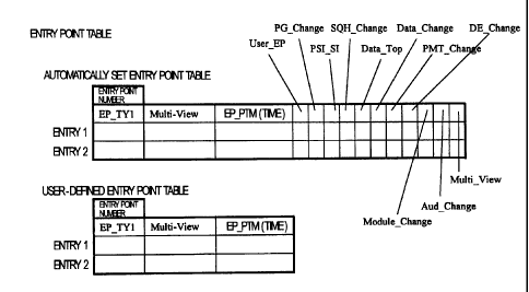
Fig. 14 shows an entry point table enabling this attribute to be set
for each entry point. The entry point table has for each entry point a USER-EP
flag indicating whether the user intentionally set a specific entry point.
This
USER_EP flag is set to 1, for example, for user-defined entry points, and is
set
to 0 for original entry points (that is, entry points set automatically by the
recorder). The recorder or player can therefore reference this flag to
determine
and clearly display for the user whether a particular entry point was set by
the
user.
Other flags and fields defined in the entry point table for each
entry point include PG_Change denoting a program change, PSI_SI denoting a
CA 02434424 2003-07-11
33
change in the PSI/SI information in the Transport Stream, SQH_Change
denoting a change in an attribute of the MPEG stream in the Transport Stream,
Data_Top denoting the starting point of a data carousel, Data_Change denoting
a point where the content changes in the data carousel, PMT Change denoting
a change in the program map table PMT, DE_Change denoting a point where
the data event is updated, Module_Change denoting a point where the module
was updated, Aud_Change denoting a change in an audio attribute, a
Multi View field declaring the number of program views in a multiview-enabled
program, and a parental control field for blocking access to certain content
by
minors, for example.
The entry point table also contains for each entry point link
information containing links to files other than AV streams and this
management
information on the optical disc. This link information is the ATS for stream
objects. For digital broadcast objects D_VOB and video objects M_VOB, this
link information is the PTS for individual entry points.
When the user sets an entry point, the recorder can display all
entry points and their attributes (PG_Change, PSI_SI, SQH_Change, Data Top,
Data_Change, PMT Change, DE_Change, Module_Change, Aud_Change,
Multi_View field, and parental control information) in a user-readable manner
regardless of whether the USER_EP flag is set. The user then marks the entry
points needed for user editing from the list of all displayed entry points and
attributes. If an entry point marked by the user is an original entry point
set by
the recorder, the recorder sets the USER_EP flag for the marked entry point is
set to 1. If the user marks an entry point that was previously marked (set) by
the
user, the USER_EP flag remains set to 1.
CA 02434424 2003-07-11
34
The user may also want to set an entry point to a point that was
not automatically detected by the recorder. In this case the user operates the
recorder to select a desired scene and then sets an entry point. When this
entry
point is recorded in the entry point table by the recorder, the USER EP flag
is
automatically set to 1.
When editing a program chain PGC the recorder displays for the
user only those entry points for which the USER_EP flag is set. This enables
the user to select only the needed entry points for program chain PGC editing
without being confused by entry points found by the recorder that were
automatically set by the recorder and are unimportant to the user.
Providing the entry point table 80d of the object information
Objectl 80 is sufficient if the entry point table is structured as shown in
Fig. 14.
As described above, however, the entry point table could be provided
separately in the user-defined PGC information 70 (see Fig. 7), in which case
it
could be written or not written to the cell information.
Automatically set entry points and user-defined entry points can
thus be separately identified by managing them using separate tables such as
shown in Fig. 15. Fig. 15 shows a table of automatically set entry points and
a
table of user-defined entry points. Because entry points are set automatically
only during recording by the recorder, the table of automatically set entry
points
is only written to the original PGC information. The entry point attributes
described above are recorded in this table. The user-defined entry point
table,
however, is written to the cell information of the user-defined PGC
information
70 (see Fig. 7). It should be noted that the table of automatically set entry
points
CA 02434424 2003-07-11
could be written to the original PGC information 50 (Fig. 7) instead of to the
object information Objectl 80 (Fig. 7).
A separate entry point table could also be provided for each view
in a multiview-enabled program. Fig. 16 shows entry point tables provided for
5 individual views. This makes managing entry points for each view easy. It
will
also be obvious that fields for recording specific attributes could also be
provided in these entry point tables for each view.
A model player for reproducing the optical disc described above is
described next below with reference to Fig. 17. As shown in Fig. 17 this model
10 player 1700 has an optical pickup 1701 for reading data from the optical
disc
100, an ECC processing unit 1702 for error correcting the read data, a track
buffer 1703 for temporarily storing the read data after error correcting, a TS
decoder 1706 for reproducing Transport Streams including video objects
M_VOB and digital broadcast objects D VOB, and a control unit 1711 for
15 controlling the various parts of the player 1700.
The player 1700 also has a digital interface 1704 for supplying an
AV stream to an external channel. This makes it possible to supply AV streams
to external devices through a communications protocol such as IEEE 1394 or
IEC 958. When new AV formats are introduced, the digital interface 1704
20 enables output to external AV devices through the digital interface 1704
without
passing through the internal decoder of the player 1700 for playback by that
external AV device. To enable the player 1700 to support a new AV format, a
decoder 1709 compatible with the new AV format can be connected to the track
buffer 1703 in the same way as other decoders.
25 The playback operation of the player 1700 is described next.
CA 02434424 2003-07-11
36
The player 1700 uses the optical pickup 1701 to read data
recorded to an optical disc 100. The ECC processing unit 1702 applies error
correction to the read data to get the Transport Stream TS. The error-
corrected
Transport Stream is then stored to the track buffer 1703. If the Transport
Stream TS can be decoded, the control unit 1711 drives the selection unit 1710
to connect the track buffer 1703 and TS decoder 1706. The TS decoder 1706
separates the Transport Stream TS into the encoded video data and audio data,
and decodes the video and audio data. The decoded video data and audio data
is then output. If the control unit 1711 determines that the Transport Stream
TS
cannot be decoded, a decoder 1709 compatible with the new AV format can be
provided for decoding.
The configuration and operation of a DVD recorder for recording
data to the above optical disc is described next below with reference to Fig.
18.
It should be noted that this DVD recorder can also play back the data recorded
to the optical disc. The playback operation is also described below.
As shown in the figure this DVD recorder 1900 has a user
interface unit 1901 as an input/output device for displaying information for
the
user and receiving user input; a system controller 1902 providing overall
management and control of the DVD recorder 1900; an analog tuner 1903 for
receiving VHF and UHF broadcasts; an encoder 1904 for converting analog
signals to digital signals and then encoding the digital signals to an MPEG
Transport Stream; a digital tuner 1905 for receiving the data stream from
digital
satellite broadcasts; an analyzing unit 1906 for analyzing a stream (MPEG
Transport Stream) including encoded digital data; a display unit 1907 such as
a
television and speakers; and a decoder 1908 for decoding AV streams.
CA 02434424 2003-07-11
37
The decoder 1908 has an additional decoder 1709 as well as the
TS decoder 1706 shown in Fig. 17.
The DVD recorder 1900 also has a digital interface unit 1909,
track buffer 1910 for temporarily storing data to be written to DVD-RAM, and a
drive 1911 having a motor for turning the DVD-RAM disc 100, a laser unit for
writing data to the DVD-RAM disc 100, and an optical pickup.
The digital interface unit 1909 is for outputting data to an external
device via a communication protocol such as IEEE 1394.
The user interface unit 1901 of this DVD recorder 1900 first
receives requests from the user. The user interface unit 1901 then passes the
request to the system controller 1902, which interprets the user request and
sends processing requests to other modules.
Operation when the user request is to record a digital broadcast is
described next with reference to Fig. 19.
Fig. 19 is a flow chart showing the recording process of the DVD
recorder 1900 shown in Fig. 18.
Digital broadcast recording requests from a user are passed from
the user interface unit 1901 to the system controller 1902. The system
controller
1902 then drives the digital tuner 1905 to receive the requested digital
broadcast, and instructs the analyzing unit 1906 to analyze the received MPEG
Transport Stream. The analyzing unit 1906 extracts and sends the start
presentation time D_VOB_V S_PTM to the system controller 1902 as the
information required to reproduce the digital broadcast object information
D_VOBI from the MPEG Transport Stream (step S191).
CA 02434424 2003-07-11
38
the analyzing unit 1906 further determines and separates the
video object units VOBU in the MPEG Transport Stream, and sends the time
length and size of the object units required for time map generation to the
system controller 1902 (step S192). The video object units VOBU are
determined by detecting I-pictures in the Transport Stream TS.
The MPEG Transport Stream sent from the digital tuner 1905 is
transferred through the analyzing unit 1906 to the track buffer 1910. The
system
controller 1902 sends a record request to the drive 1911, and the drive 1911
reads and records data from the track buffer 1910 to the DVD-RAM disc 100
(step S193). The system controller 1902 also tells the drive 1911 where to
record the data on the disc based on file system allocation data.
The analyzing unit 1906 monitors the MPEG Transport Stream
being received while detecting object unit time information to detect any
attribute changes (step S194). A specific method for detecting attribute
changes
in digital satellite broadcasts is described below. To do this the recorder
detects
change in the parameters labelled (a) to (k) below, and therefore has memory
sufficient to store a specific amount of previously received data.
It should be noted that this detection method is just one example
and while there are cases in which the data structure does not conform in part
to the ARIB-standard data structure, detection using a data structure
compliant
with the ARIB standard is also possible.
(a) PG_Change: Added when change is detected in the event id
parameter of the Event-Information-Table (EIT) in the digital broadcast stream
(see Fig. 20).
CA 02434424 2003-07-11
39
(b) PSI/SI: Added when change is detected in the version-number
parameter in the PAT (Program-Association-Table), CAT
(Conditional_Access_Table), NIT (Network-Information-Table), BIT
(Broadcaster-information-Table), SDT (Service-Description-Table), or EIT
(Event_Information_Table) (see Fig. 21).
(c) SQH_Change: Added when change is detected in the sequence
header in an MPEG-2 stream of a digital broadcast stream (see Fig. 22).
(d) Data_Top: Added when change is detected in the
dsmccMessageHeader() parameter of the DII (Download Info Indication) in the
digital broadcast stream (see Fig. 23).
(e) Data_Change: Added when change is detected in the
transaction-id in the dsmccMessageHeader() parameter of the DII in the digital
broadcast stream (see Fig. 24).
(f) PMT Change: Added when change is detected in the
version-number parameter in the PMT (Program_Map_Table) in the digital
broadcast stream (see Fig. 25).
(g) DE_Change: Added when change is detected in the
data-event-id parameter in the downloadlD of the DII message in the digital
broadcast stream (see Fig. 26).
(h) Module Change: Added when change is detected in the
module-version parameter of the DII message in the digital broadcast stream
(see Fig. 27).
(i) Aud_Change: Added when change is detected in the
component-type or the sampling_rate parameter in the audio component
descriptor of the EIT in the digital broadcast stream (see Fig. 28).
CA 02434424 2003-07-11
(j) Multi View: Added when change is detected in the num_of group
parameter in the component group descriptor in the EIT of the digital
broadcast
stream (see Fig. 29).
(k) Parental control: Added by referencing the private-data-byte
5 parameter in the restricted reception descriptor of the PMT in the digital
broadcast stream, or the parental rating information of the rating field in
the
parental rating descriptor of the EIT (see Fig. 30).
Referring again to Fig. 19, when the analyzing unit 1906 detects a
change in MPEG Transport Stream content it sends the detected information
10 and the time when the change was detected as entry point data to the system
controller 1902 (step S195). The system controller 1902 produces an entry
point
table collecting this entry point data.
Whether recording is to end or not is controlled according to a
stop-recording request from the user (step S196). Stop-recording requests from
15 the user are passed through the user interface unit 1901 to the system
controller 1902, and the system controller 1902 then sends a stop-recording
instruction to the digital tuner 1905 and analyzing unit 1906. Processing
repeats
and recording continues from step S192 if there is no stop-recording request
from the user.
20 When the analyzing unit 1906 receives a stop analyzing request
from the system controller 1902, it stops the data analysis process and sends
the last end presentation time D_VOB_V E_PTM in the last-analyzed video
object unit VOBU of the MPEG Transport Stream to the system controller 1902.
After ending the digital broadcast reception process, the system
25 controller 1902 produces the digital broadcast object information D_VOBI
based
CA 02434424 2003-07-11
41
on information received from the analyzing unit 1906, and then generates cell
information corresponding to this digital broadcast object information D_VOBI.
The type information Type of the cell information is set to "D_VOB" at this
time.
The system controller 1902 also generates an entry point table from the entry
point data received from the analyzing unit 1906 (step S197). The system
controller 1902 also sets the view type parameter View type of the recorded
cell based on the entry point data.
Finally, the system controller 1902 instructs the drive 1911 to
finish recording the data accumulated in the track buffer 1910, and to record
the
digital broadcast object information and cell information. The drive 1911 then
records the remaining data in the track buffer 1910, the digital broadcast
object
information D_VOBI, and the cell information to the DVD-RAM disc 100, and
ends the recording process (step S198).
The same basic process is performed when the user request is to
record an analog broadcast. Operation differs in that the video object units
VOBU are generated by the recorder because the Transport Stream TS is
encoded by the encoder 1904.
The same basic process is also performed when the user request
is for stream recording. Operation differs, however, in that the time
information
is set based on the ATS because the stream objects SOB are not analyzed.
Operation has been described above based on start-recording
and stop-recording requests from the user. It should be noted that this DVD
recorder 1900 can also be used for time-shift or programmed recording
similarly
to timer recording programs executed by conventional VCR decks. In this case
the operation of the DVD recorder 1900 differs from that described above only
CA 02434424 2003-07-11
42
in that the start and stop recording requests are asserted automatically by
the
system controller 1902 instead of by the user.
Operation of the DVD recorder 1900 when the user request is to
play data recorded to this DVD-RAM disc 100 is described next with reference
to Fig. 31. Fig. 31 is a flow chart of the playback process executed by the
DVD
recorder 1900 shown in Fig. 18. Playing an original program chain PGC
composed of one digital broadcast object D_VOB and one cell information block
is described below. It should be noted that the DVD player 1700 shown in Fig.
17 and described above can also execute the playback operation described
below.
First, the user interface unit 1901 receives an original program
chain PGC playback request from the user. The user interface unit 1901 passes
the user request to the system controller 1902, which determines the user
request to be an original PGC playback request and sends corresponding
processing requests to the other modules.
The system controller 1902 analyzes the PGC information 50 and
cell information 60 (Fig. 7) to identify the object to be reproduced (step S31
1).
More specifically, the system controller 1902 first interprets the type
information
Type of the cell information in the PGC information. If the Type is "D_VOB"
the
system controller 1902 knows the AV stream to be reproduced is an AV stream
recorded as an MPEG Transport Stream.
Next, the system controller 1902 searches the digital broadcast
file management table D_AVFIT 94 to retrieve the corresponding digital
broadcast object information D_VOBI based on the ID in the cell information
(step S312). Then, based on the start presentation time D_VOB_V S_PTM and
CA 02434424 2003-07-11
43
end presentation time D_VOB_V E_PTM of the video object information, and
the time map, the system controller 1902 determines the location of the object
on the DVD-RAM disc 100 (step S313). Once the location of the object is
identified, the system controller 1902 gets the start and end addresses on the
DVD-RAM disc 100 of the AV data to be reproduced based on the time map
and the start and end address information in the cell information (step S314).
When the address to be accessed is acquired the system
controller 1902 sends a request to read from the DVD-RAM disc 100 together
with the read address to the drive 1911. The drive 1911 then reads the AV data
from the address specified by the system controller 1902, and stores the read
data to the track buffer 1910 (step S315).
The system controller 1902 then sends a decode request to the
decoder 1908. The decoder 1908 thus reads and decodes the AV data stored in
the track buffer 1910. The decoded AV data is then output through the display
unit 1907 (step S316).
The drive 1911 then determines whether reading all data specified
by the system controller 1902 is finished (step S317). If it is not, the
process
repeats from step S315 and reading the AV data continues. If it has finished,
the drive 1911 tells the system controller 1902 that reading is completed, and
the system controller 1902 then sends a playback completion request to the
decoder 1908.
The decoder 1908 continues playback until the track buffer 1910
is empty. When the track buffer 1910 is empty and decoding and playback of all
data is completed, the decoder 1908 tells the system controller 1902 that
playback is completed and the playback process ends.
CA 02434424 2003-07-11
44
Playback of an original PGC composed of one digital broadcast
object D_VOB and one cell information block is described above. It will be
obvious, however, that an AV stream can be played back by performing the
same process when the original program chain PGC contains one video object
M VOB, when it contains multiple video objects M_VOB, when it contains
multiple digital broadcast objects, or when it contains a combination of video
objects and digital broadcast objects. The AV stream can also be reproduced
when the original program chain PGC contains a plurality of cells. This
playback
process also applies to user-defined program chains PGC.
Playback of stream objects SOB when the decoder 1908 does not
have a playback function for all AV streams is described next. Referring again
to Fig. 18, if the decoder 1908 does not have a playback function for
reproducing the MPEG Transport Stream, for example, the stream cannot be
reproduced through the decoder 1908 as described above. In this case the data
is passed to an external device through the digital interface unit 1909, and
the
data is decoded and reproduced by the external device.
If the system controller 1902 detects that the cell information in the
PGC information selected by the user for playback is a stream object SOB not
support by the system, it instructs the digital interface unit 1909 to
externally
output the data instead of sending a playback request to the decoder 1908. The
digital interface unit 1909 thus transmits the AV data stored in the track
buffer
1910 according to the communication protocol of the connected digital
interface.
Except for these steps, the playback process is the same as the playback
process used for digital broadcast objects D_VOB.
CA 02434424 2003-07-11
Whether the decoder 1908 is compatible with the AV stream
selected for playback can be determined by the system controller 1902, or by
the system controller 1902 querying the decoder 1908. The decoder 1908 in
this case checks the Program Specific Information PSI or Service Information
SI
5 in the MPEG Transport Stream to determine if it is compatible with the
stream.
It is important to note that there are times when the stream
content cannot be interpreted for a stream object SOB, and playback
capabilities are therefore partially limited. So-called special playback modes
such as slow playback, for example, require repeated transmission of stream
10 data that cannot be reproduced independently, that is, without reference to
preceding and following picture data, and such playback modes are therefore
difficult to achieve with a stream object SOB if the stream data content
cannot
be analyzed.
To resolve this problem, the DVD recorder 1900 according to this
15 embodiment of the invention references the type information Type of the
cell
when a special playback mode request is received from the user, for example,
and if a SOB is detected sends to the user interface unit 1901 a message
reporting that the selected special playback mode cannot be used.
Furthermore, because stream object SOB playback can be limited
20 as described above, it is also possible to prohibit mixing stream objects
SOB
and other objects, such as digital broadcast objects D_VOB and video objects
M_VOB, in one program chain PGC when creating a program chain PGC
defining the playback sequence of a continuous AV stream.
The process executed when there is a request to set a user-
25 defined entry point in an optical disc recording AV data is described next.
CA 02434424 2003-07-11
46
Fig. 32 is.a flow chart of a process for setting user-defined entry
points.
If a request to set a user-defined entry point is received through
the user interface unit 1901 (Fig. 18) (step S321), the system controller 1902
(Fig. 18) reads the entry point table from disc and presents all entry points
in the
entry point table for the cell and the defined entry point attributes on the
user
interface unit 190 (step S322). The entry point tables referred to here are
the
automatically set entry point table and the user-defined entry point table
shown
in Fig. 15. More specifically, these entry point tables are the entry point
table 72
of cell information 71 for the user-defined PGC information 70 (Fig. 7), and
the
entry point table 80d of the object information Objectl 80 (Fig. 7). It is
also
possible to reference only the user-defined entry point table. It is also
possible
to not present the attribute information if it is not particularly needed.
This attribute information includes the following flags and fields in
the present embodiment: PG_Change denoting a program change, PSI_SI
denoting a change in the PSI/SI information in the Transport Stream,
SQH_Change denoting a change in an attribute of the MPEG stream in the
Transport Stream, Data_Top denoting the starting point of a data carousel,
Data_Change denoting a point where the content changes in the data carousel,
PMT Change denoting a change in the program map table PMT, DE_Change
denoting a point where the data event is updated, Module_Change denoting a
point where the module was updated, Aud_Change denoting a change in an
audio attribute, a Multi_View field declaring the number of program views in a
multiview-enabled program, and a parental control field.
CA 02434424 2003-07-11
47
Based on all of the displayed entry points and the attribute
information, the user can easily find as needed a particular point for
starting
playback, a desired scene in a particular program, a desired digital broadcast
program, or a desired scene in a program with multiple views.
The user then instructs the DVD recorder 1900 to set a marker
denoting the selected entry point (step S323). When the system controller 1902
of the DVD recorder 1900 receives the set marker command for a particular
entry point from the user, it adds an entry in the user-defined entry point
table
(step S324).
To set an entry point at a point other than the location of an
original entry point, the user specifies the starting point and end point of
the
stream segment where the entry point is to be set. Based on the received
starting point information, the system controller 1902 of the DVD recorder
1900
gets the time information PTS corresponding to that starting point. The system
controller 1902 then adds an entry to the user-defined entry point table, and
writes the acquired presentation time stamp PTS to the entry point time
EP_PTM field.
If instead of providing two different entry point tables as shown in
Fig. 15 a single table is used to manage both automatically set entry points
and
user-defined entry points, that is, an entry point table as shown in Fig. 14
is
used, the USER_EP flag of the entry point table is set.
The process ends when all entry points have been set (step S324).
If setting entry points is not completed, the procedure repeats from step
S322,
and all entry points set to that point and the corresponding attributes are
displayed.
CA 02434424 2003-07-11
48
A playback process starting from a user-defined entry point is
described next with reference to Fig. 33. Fig. 33 is a flow chart showing the
user-defined entry point playback process.
When the system controller 1902 receives a user-defined entry
point playback request (step S331), it determines if a user-defined entry
point
table (that is, entry point table 72 or the lower table shown in Fig. 15) is
found
on the optical disc (step S332). If a user-defined entry point table is
present the
system controller 1902 reads and stores the table to display memory, and
displays the table (step S334). This enables the user to select the playback
starting point from among only the required user-defined entry points without
being confused by numerous entry points of which the user is unaware also
being displayed.
If a user-defined entry point table is not on the disc, the system
controller 1902 reads and stores the automatically set entry point table to
display memory, and displays the automatically set entry points (step S334. If
the entry point table in Fig. 14 is used, the USER EP flag can be checked for
each entry point to determine if the flag is set and only the entry points for
which
the USER EP flag is set are read.
When the user then selects an entry point, the system controller
1902 receives information identifying the selected entry point from the user
interface unit 1901 (step S335). The system controller 1902 then detects the
entry point time EP_PTM for the selected entry point from the entry point
table
(step S336). The precision of this time information for each entry point in
the
entry point table is normally the precision defined in the MPEG standard,
i.e., 27
CA 02434424 2003-07-11
49
MHz. It could also be the video frame count or a value obtained by dropping
the
lowest few bits of a 90 KHz or 27 MHz bitrate.
The system controller 1902 then converts this time information to
a disc sector address using the time map of the object information for the
object
(D_VOB) (step S337). The system controller 1902 then starts playback of the
MPEG Transport Stream from this sector address (step S338).
Video and audio can thus be played back from a particular scene,
that is, entry point, chosen by the user. The system controller 1902
references
the view type parameter View type of the cell information. If View-type is any
value other than 0, that is,. it indicates a multiview stream, the view type
View type of the cell information is reported to the user interface unit 1901.
Based on this View type the DVD recorder 1900 displays the number of views
available on the screen of the user interface unit 1901, such as in an on-
screen
display (OSD).
All entry points are displayed by the processes shown in Fig. 32
and Fig. 33 as described above. However, it is not necessary to always display
all entry points. For example, only the entry points for which a change in a
specific attribute is detected could be displayed, or only entry points found
in a
specified time period could be displayed. This selection can be made based on
the attributes contained in the entry point tables or on the entry point time
EP_PTM value.
Furthermore, when the DVD recorder reproduces an AV stream
not supported by the decoder, the stream is reproduced through a digital
interface in the above embodiments. However, even AV streams supported by
CA 02434424 2003-07-11
the decoder could be passed through a digital interface and output to a set-
top
box or other external device as instructed by the user.
Furthermore, the present invention has been described as an
optical disc, optical disc recorder, and optical disc player, but the same
effect
5 can be achieved by means of the same components and the same processes
as described above even if the MPEG Transport Stream is recorded to a hard
disk or other storage medium. The invention is therefore not limited to
physical
media. In this case the "same components" can be achieved by the central
processing unit (CPU) of a personal computer and an image processing chip,
10 for example. The CPU and other components in this case operate according to
a recording program executable by a computer according to processes as
shown in the flow charts in Fig. 19 and Fig. 31 to Fig. 33.
This computer-executable program could be stored to floppy disk,
optical disc, semiconductor memory, or other recording medium. It could also
15 be transferred over the Internet or other communication medium and
installed to
a personal computer.
This preferred embodiment of the invention has been described
using by way of example an MPEG Transport Stream as the self-encoded
stream. An MPEG Program Stream or a stream in some other format could
20 alternatively be used, however.
Application in industry
A transport stream received via a digital broadcast can be
recorded together with other AV streams, and entry points defined by a user in
CA 02434424 2003-07-11
51
the recorded digital broadcast object can be discriminated from entry points
set
by the system with a data recording medium according to the present invention.
Furthermore, by defining in the entry point data written to the entry
point table a flag denoting a program change, a flag denoting a change in the
PSI/SI information, a flag denoting a change in an attribute of the MPEG
stream,
a flag denoting the starting point of a data carousel, a flag denoting a point
where the content changes in the data carousel, a flag denoting a change in
the
content of the program map table PMT, a flag denoting a point where a module
was updated, a flag denoting a point where the data event changed, a flag
denoting a change in an audio attribute, a field declaring the number of
program
views in a multiview-enabled program, and a parental control field, this
information can be displayed for the user to make it easier for the user to
find a
desired scene. If a cell contains multiple views, this and the number of views
can also be displayed for the user.
Although the present invention has been described in connection
with the preferred embodiments thereof with reference to the accompanying
drawings, it is to be noted that various changes and modifications will be
apparent to those skilled in the art. Such changes and modifications are to be
understood as included within the scope of the present invention as defined by
the appended claims, unless they depart therefrom.