Language selection

Search

Patent 2434442 Summary

Third-party information liability

Some of the information on this Web page has been provided by external sources. The Government of Canada is not responsible for the accuracy, reliability or currency of the information supplied by external sources. Users wishing to rely upon this information should consult directly with the source of the information. Content provided by external sources is not subject to official languages, privacy and accessibility requirements.

Claims and Abstract availability

Any discrepancies in the text and image of the Claims and Abstract are due to differing posting times. Text of the Claims and Abstract are posted:

  • At the time the application is open to public inspection;
  • At the time of issue of the patent (grant).
(12) Patent: (11) CA 2434442
(54) English Title: REFLECTION-PHOTOMETRIC ANALYTICAL SYSTEM
(54) French Title: SYSTEME D'ANALYSE PHOTOMETRIQUE PAR REFLEXION
Status: Deemed expired
Bibliographic Data
(51) International Patent Classification (IPC):
  • G01N 21/78 (2006.01)
  • G01S 17/48 (2006.01)
(72) Inventors :
  • ZIEGLER, FRIEDRICH (Germany)
(73) Owners :
  • F. HOFFMANN-LA ROCHE AG (Switzerland)
(71) Applicants :
  • F. HOFFMANN-LA ROCHE AG (Switzerland)
(74) Agent: NORTON ROSE FULBRIGHT CANADA LLP/S.E.N.C.R.L., S.R.L.
(74) Associate agent:
(45) Issued: 2011-06-14
(22) Filed Date: 2003-07-08
(41) Open to Public Inspection: 2004-01-19
Examination requested: 2003-07-08
Availability of licence: N/A
(25) Language of filing: English

Patent Cooperation Treaty (PCT): No

(30) Application Priority Data:
Application No. Country/Territory Date
102 33 087.5 Germany 2002-07-19

Abstracts

English Abstract


The invention concerns a reflection-photometric analytical system having a
measuring head (10) comprising a source of radiation (36) and a radiation
detector
(26) for the reflection-photometric analysis of a target surface (12) of a
test object
(14) arranged at a distance from the measuring head (10) and in particular of
a test
strip for body fluids such as urine or blood. A triangulation unit (16)
operating on the
basis of optical triangulation is proposed for checking the distance without
making
contact in order to monitor or regulate the measuring distance.


French Abstract

Cette invention traite d'un système d'analyse photométrique par réflexion. Ce système comprend les éléments qui suivent. Une tête de mesure (10) comprenant une source de rayonnement (36) et un détecteur de rayonnement (26) pour l'analyse photométrique par réflexion d'une surface cible (12) d'objet test à contrôler (14) distant de la tête de mesure (10) et en particulier d'une bandelette réactive pour les liquides organiques, comme l'urine ou le sang. Une unité de triangulation (16) dont le fonctionnement repose sur la triangulation optique permet de contrôler la distance, sans effectuer de contact, afin de contrôler ou de réguler la distance de mesure.

Claims

Note: Claims are shown in the official language in which they were submitted.


-9-

Claims:


1. Reflection-photometric analytical system comprising a measuring
head (10) consisting of a radiation source (36) and a radiation detector (26)
for
the reflectometric examination of a target surface (12) of a test object (14)
which is arranged at a distance from the measuring head (10), characterized by

a triangulation unit (16) operating on the basis of optical triangulation for
checking the distance of the measuring head (10) from the target surface (12)
without contact; said triangulation unit (16) having a light emitter(34)
having a
modulation stage (54) for the time-varying actuation of a light source (38).

2. Analytical system as claimed in claim 1, characterized in that the light
emitter (34) is directed towards the target surface (12) in an incidence axis
(42); and the triangulation unit (16) has a light receiver (48) pointing
towards
the target surface (12) in the direction of a receiving axis (50).

3. Analytical system as claimed in claim 2, characterized in that the
incidence and receiving axis (42, 50) intercept at a reference point (52) at a

specified angle and the reference point (52) defines a reference position of
the
target surface 12.

4. Analytical system as claimed in claim 2 or 3, characterized in that the
incidence and receiving axis (42, 50) enclose different angles relative to a
perpendicular on the target surface (12).

5. Analytical system as claimed in any one of claims 2 to 4, characterized
in that the light receiver (48) has a position resolving sensor at right
angles to
the receiving axis (50).


-10-

6. Analytical system as claimed in claim 5, characterized in that the
position resolving sensor is a PSD sensor, CCD sensor or multi-element diode
sensor (46).

7. Analytical system as claimed in any one of claims 2 to 6, characterized
in that the light receiver (48) is a double sensor with two single sensors
(46).
8. Analytical system as claimed in any one of claims 2 to 6, characterized
in that the light receiver (48) is a double sensor with two single sensors
(46)
arranged next to one another and symmetrically to the receiving axis (50).

9. Analytical system as claimed in any one of claims 2 to 8, characterized
in that the light receiver (48) has a collecting optical system (44) whose
optical
axis defines the receiving axis (50) for focussing the light reflected from
the
target surface (12).

10. Analytical system as claimed in any one of claims 2 to 9, characterized
in that said light source (38) is a point light source; and the light
emitter(34)
has a collimating optical system (40) whose optical axis defines the incidence

axis (42) for generating a light beam which is incident on the target surface
(12).

11. Analytical system as claimed in any one of claims 1 to 10, characterized
in that the modulation stage (54) provides a pulsed-shaped actuation of the
light
source (38).

12. Analytical system as claimed in any one of claims 2 to 11, characterized
in that the light emitter (34) has an edge generator (56) to produce non-
linear
light pulses.


-11-

13. Analytical system as claimed in any one of claims 2 to 11, characterized
in that the light emitter (34) has an edge generator (56) to produce non-
linear
and exponentially increasing or decreasing light pulses.

14. Analytical system as claimed in any one of claims 1 to 13, characterized
in that the triangulation unit (16) has a signal processing circuit (60) for
determining changes in the distance relative to a reference position on the
target surface (12).

15. Analytical system as claimed in claim 14, characterized in that the signal

processing circuit (60) has a comparator (64) and a timer (66) to determine
the
time interval of specified signal amplitudes of output signals of the
triangulation unit (16).

16. Analytical system as claimed in any one of claims 1 to 15, characterized
by a control device (18) that interacts with the triangulation unit (16) to
set a
specified distance between the target surface (12) and measuring head (10) by
means of a servodrive (28).

17. Analytical system as claimed in any one of claims 1 to 16, characterized
in that the path of the measuring head (10) can be recorded by a path
measuring
device (74) to determine a height profile of the test object (14).

18. Analytical system as claimed in claim 17, characterized in that the path
measuring device (74) has a height profile store (78) to identify the test
object
(14).

19. Analytical system as claimed in any one of claims 1 to 18, characterized
in that the triangulation unit (16) has a subsequent evaluation unit to


-12-


standardize the results of the photometric analysis on the basis of the
distance
between the target surface (12) and measuring head (10).

20. Analytical system as claimed in any one of claims 2 to 19, characterized
in that the light source (36) is at the same time the light emitter (34).

21. Analytical system as claimed in any one of the claims 2 to 20,
characterized in that the radiation detector (26) is at the same time the
light
receiver (48) of the triangulation unit (16).

22. Analytical system as claimed in any one of claims 1 to 21, characterized
in that the test object (14) is a test strip for body fluids.

23. Analytical system as claimed in any one of claims 1 to 21, characterized
in that the test object (14) is a test strip for body fluids selected from
urine and
blood.

24. Method for the reflectometric analysis of a target surface (12) of a test
object (14) arranged at a distance from the measuring head (10) characterized
in that the measuring distance between the measuring head (10) and target
surface (12) is examined by means of a triangulation unit (16) on the basis of

optical triangulation; said triangulation unit (16) having a light emitter(34)

having a modulation stage (54) for the time-varying actuation of a light
source
(38).

25. Method as claimed in claim 24, characterized in that the changes in the
distance are detected relative to a reference distance of the target surface
(12)
by means of a corresponding light deflection onto a light receiver (48) of the

triangulation unit (16).


-13-

26. Method as claimed in claim 24 or 25, characterized in that the measuring
distance is kept constant by means of a control device (18).

27. Method as claimed in any one of claims 24 to 26, characterized in that
the modulation stage (54) provides a pulsed-shaped actuation of the light
source (38).

28. Method as claimed in any one of claims 24 to 27, characterized in that
the test object (14) is a test strip for body fluids.

29. Method as claimed in any one of claims 24 to 27, characterized in that
the test object (14) is a test strip for body fluids selected from urine and
blood.

Description

Note: Descriptions are shown in the official language in which they were submitted.


CA 02434442 2003-07-08

-1-
Reflection-photometric analytical system
Description

The invention concerns a reflection-photometric analytical system having a
measuring head comprising a source of radiation and a radiation detector for
the
reflectometric analysis of a target surface of a test object arranged at a
distance from
the measuring head and in particular of a test strip for body fluids such as
urine or
blood. The invention also concerns a corresponding measuring method.

Systems of this type are used particularly in the field of clinical analysis
in order to
determine the presence and concentration of certain analytes in a sample
liquid by
means of test strips. A spectroscopic analysis of radiation reflected from
irradiated
test fields of the test strips is carried out in automated instruments. A
critical factor
for reflectometric measurement is a constant measuring distance where it is
necessary to take into account that the test fields can have different heights
and that
absorption of the sample liquid can result in different degrees of swelling.
It has been
attempted to reduce the distance dependency by using a receiving optical
system
having a long focal length and a greatly reduced optical aperture which is
aligned
perpendicularly to the target surface. However, this requires a large space
and the
signal currents of the photodetector are small and thus require complicated
measurement instrumentation to process them.

A sensor for distance measurement and a control unit for adjusting the
measuring
distance has already been proposed in JP-A 03-166738 (publication number
10948/1993) in a similar context. However, it does not disclose anything about
the
operating principle of the distance detection. A general problem is that the
surface
properties of test strips can vary greatly due to the application of sample
liquid since
almost dry, rough surfaces as well as wet and hence shiny surface may be
present.
This was the starting point for the invention whose object is to avoid the
disadvantages of the prior art and to improve an analytical system and a
method of


CA 02434442 2008-05-01

-2-
the type described above in such a manner that a high measuring accuracy is
achieved even when the target surface has a variable height profile. In
particular, it should enable a reliable control of the measuring distance.

In one aspect of the invention, there is provided a reflection-photometric
analytical system comprising a measuring head consisting of a radiation source
and a radiation detector for the reflectometric examination of a target
surface of
a test object which is arranged at a distance from the measuring head,
characterized by a triangulation unit operating on the basis of optical
triangulation for checking the distance of the measuring head from the target
surface without contact; said triangulation unit having a light emitter having
a
modulation stage for the time-varying actuation of a light source.

In another aspect of the invention, there is provided a method for the
reflectometric analysis of a target surface of a test object arranged at a
distance
from the measuring head and in particular of a test strip for body fluids such
as
urine or blood characterized in that the measuring distance between the
measuring head and target surface is examined by means of a triangulation unit
on the basis of optical triangulation; said triangulation unit having a light
emitter having a modulation stage for the time-varying actuation of a light
source.

The invention is based on the idea that a change in the measuring distance can
be detected in a position resolving manner by a corresponding change in the
path of the rays. Correspondingly, the invention proposes a triangulation unit
operating on the basis of optical triangulation for checking the distance
between the measuring head and target surface without contact. The influence
of variations in the height of the target surface can be eliminated in a
simple
DOCSMTL: 2708629\l


CA 02434442 2008-05-01

- 2a -

manner by this means without impairing the efficiency of the photometric
measuring system. This would enable any measuring sites to be probed on the
target surface and in particular also measuring sites that reflect completely
diffusely.
The triangulation method has a high distance resolution and can operate
substantially in real time during positioning movements.

The triangulation unit advantageously has a light emitter directed onto the
target
surface in an axis of incidence and a light receiver pointing towards the
target
surface oriented in a receiving axis. In this connection, it is advantageous
for
reference measurements when the incidence and receiving axis intersect a
reference
point at a predetermined angle where the reference point defines a set
position of the
target surface.

In order to preferably detect diffusely back-scattered light, it is
advantageous when
the incidence and receiving axis enclose different angles relative to a
perpendicular
on the target surface.

In order to detect the light deflection correlating with the change in
distance, a
preferred embodiment provides that the light receiver has a position-resolving
sensor
DOCSMTL: 2708629\1


CA 02434442 2003-07-08

-S-
at right angles to the receiving axis. In this case a PSD sensor (position
sensing
detector), CCD sensor (charge coupled device) or multi-element diode sensor
can be
advantageously used.

In a particularly simple embodiment the light receiver is a double sensor with
two
single sensors in particular single diodes arranged side by side and
preferably
symmetrically to the receiving axis. This allows the detection of distance
variations
by means of the resulting differences in the illumination of the single
sensors.
Another advantageous embodiment provides that the light receiver has a
collecting
optical system whose optical axis defines the receiving axis for focussing the
light
reflected from the target surface, and that the light emitter has a light
source, in
particular a point light source and a collimating optical system whose optical
axis
defines the incidence axis for producing a light beam incident on the target
surface.
According to a further preferred embodiment of the invention the light emitter
has a
modulation stage for the time-varying and preferably pulsed shaped actuation
of a
light source. This improves the tolerance compensation of the reflection
factor and
simplifies the detection electronics. For this it is preferable that the light
emitter has
an edge generator to produce non-linear and preferably exponentially
increasing or
decreasing light pulses.

The triangulation unit advantageously has a signal processing circuit for
determining
changes in the distance relative to a reference position on t:he target
surface. In order
to relate changes in position to a time measurement it is advantageous when
the
signal processing circuit has a comparator and a timer to determine the time
interval
of specified signal amplitudes of output signals of the triangulation unit.

Another preferred embodiment provides a control device that interacts with the
triangulation unit to set a specified distance between the target surface and
measuring
head by means of a servodrive.


CA 02434442 2003-07-08

-4-
An additional benefit can be achieved when the path of the measuring head can
be
recorded by a path measuring device to determine a height profile of the test
object
and that the path measuring device has a height profile store to identify the
test
object.

Instead of the distance regulation it is also conceivable that the
triangulation unit has
an evaluation unit to standardize the results of the photometric analysis on
the basis
of the distance between the target surface and measuring head.

An additional functional simplification is achieved when the light source is
at the
same time the light emitter and/or the radiation detector is at the same time
the light
receiver of the triangulation unit.

The above-mentioned object is achieved by a method in which the measuring
distance between the measuring head and target surface is examined without
contact
by a triangulation unit on the basis of optical triangulation. Changes in the
distance
are preferably detected relative to a specified distance of the target surface
by means
of an appropriate light deflection onto a light receiver of the triangulation
unit.
Another advantageous procedure provides that the measuring distance is kept
constant by means of a control device.

The invention is elucidated further in the following on the basis of an
embodiment
which is shown schematically in the drawing.

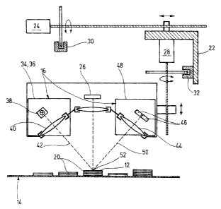
Fig. 1 shows a diagram of a reflection photometer having a triangulation unit
to
control the measuring distance.

Fig. 2 shows a block diagram of a generator circuit for triggering the pulses
of a
light emitter of the triangulation unit.

Fig. 3 shows a block diagram of a distance control device interacting with the
triangulation unit.


CA 02434442 2003-07-08

-5-
Fig. 4 shows a block diagram of a path recording system to determine the
height
profile of the test object to be examined and

Fig. 5 shows a time diagram of light signals detected by the triangulation
unit.
The reflection photometric analytical system shown in the diagram essentially
consists of a measuring head 10 for the reflectometric examination of the
target
surface 12 of an analytical test strip 14, a triangulation unit 16 to check or
detect the
measuring distance between the measuring head 10 and target surface 12 and a
control device 18 to set a constant measuring distance.

As shown in fig. 1, the test strip 14 has different test fields 20 which are
used to
detect specific analytes in a body fluid to be examined such as urine or
blood. For
this purpose the measuring head 10 can be moved on a slide 22 towards the
strip by
means of a forward feed drive 24 during which the photodetector 26 of the
photometer detects the light reflected from the target surface 12 of the test
fields 20.
In this process a constant measuring distance can be set between the
photodetector 26
and the target surface 12 of the test fields 20 of different thicknesses by
means of a
adjusting drive 28 of the control device 18. Angle transmitters 30, 32 that
are
sensitive to the direction of rotation are located on the rotating spindles of
the drives
24, 28 to detect the path of travel of the measuring head 10. These generate
counting
pulses during a rotary movement from which a linear path can be calculated
according to the spindle pitch.

The triangulation unit 16 has a light emitter 34 which is at the same time the
radiation source 36 for the reflectometric measurement. The light emitter 34
comprises a semiconductor diode 38 as a light source and a collimatic optical
system
40 to produce a light beam in the direction of an incidence axis 42 directed
onto the
target surface 12.

In order to detect the light beam reflected from the target surface 12, the
triangulation
unit 16 has a light receiver 48 comprising a collecting optical device 44 and
a double


CA 02434442 2003-07-08

-6-
diode sensor consisting of two single diodes 46. The optical axis of the
collecting
optical device 44 defines a receiving axis 50 which intersects the incidence
axis 42 at
a reference point 52 that determines a set position on the target surface 12.
The single
diodes 46 are arranged side by side and symmetrically to the receiving axis 50
and
their receiving surface faces the target surface 12 such that both single
diodes 46 are
illuminated equally in the set position. When a movement occurs away from the
set
position, the focus of the received light beam moves correspondingly
transversely to
the receiving axis 50 in the plane defined by the incidence and receiving axis
and as
a result one of the single diodes 46 is illuminated more strongly than the
other. The
difference in illumination corresponds to the change in distance.

As illustrated in fig. 2 the light source 38 can be actuated in pulses by
means of a
generator circuit. This consists of a modulation stage 54 to determine the
pulse
intervals, an edge generator 56 to produce exponentionally decreasing light
pulse
flanks and a voltage current converter 58 to supply the light source 38 with
power
whereby the light intensity follows the time course of the current pulses.

As shown in fig. 3 the output signals of the light receiver 34 can be analysed
by a
downstream signal processing circuit 60 in the sense of a distance check which
is
described below in more detail. For this purpose the single diodes 46 are each
connected via a current-voltage converter 62 and a threshold value comparator
64
with a timer 66 and a phase comparison element 68. A subsequent integrator
stage 70
converts the time difference of the comparator signal allocated to a light
pulse into a
corresponding voltage signal with the correct polarity sign. This can be fed
as an
adjusting signal to an analogue amplifier stage 72 to actuate the positioning
drive 28.
In this manner the circuit shown in fig. 3 forms the control device 18 which
ensures
the maintenance of the reference position and a predetermined measuring
distance
when measuring the various test fields 20.

The path recording system 74 shown in fig. 4 enables an identification of the
test
strip 14 on the basis of the height profile of its test fields 20. For this
purpose the


CA 02434442 2003-07-08

-7-
counting pulses of the angle transmitter 30, 32 are counted in a
microcontroller 76 in
order to determine the current position or path of travel of the measuring
head 10
starting from an initial position. The distance control results in a height
profile when
the forward feed drive 24 is operated which can be compared with stored data
in a
height profile memory 78 in order to decide on the validity of the
measurement.

In general measuring distance by triangulation is based on a comparison of
similar
triangles which are subtended between the collecting lens and receiver as an
object
triangle between the object and collecting lens and as an image triangle
between the
collecting lens and receiver in accordance with. the optical path. According
to the
invention the method is limited to measurements relative to a reference plane
in
which an image point of the detection light (diffusely) reflected by the test
object is
deflected on the receiver surface by a change in the distance. The spatial
deflection
can be converted back into a time measurement due to the pulse modulation of
the
detection light as a result of which tolerances in the optical. efficiency of
the
measuring system due to the exponential intensity time course have essentially
no
effect.

This mode of operation is further illustrated in fig. 5 by a time course of
the receiver
signals of the single diodes 46 for the case of a first reflection factor of
the target
surface 12 (continuous curves) and a second reflection factor which is reduced
by
half (dashed curves). It is assumed that there is a deviation from the
reference
position which results in an unsymmetric illumination of the single diodes 46
and
correspondingly to different initial amplitudes. In the case of a decreasing e-
function-
modulated illumination intensity, this results in different trigger times for
the
threshold value Imo, of the comparators 64 whose time difference At is
detected by
means of the timer 66. The direction of the change in distance is determined
by the
time sequence of the trigger signals in the phase comparison element 68. As
shown
in fig. 5 the time intervals At are equal for both reflection factors. In
mathematical
terms it can be shown that in the neighbourhood of the reference distance the
time
different At is independent of the reflection factor and essentially linearly
dependent


CA 02434442 2003-07-08

on the change in the distance h. Hence the arrangement described above
creates a
robust control unit with good control properties.

Representative Drawing
A single figure which represents the drawing illustrating the invention.
Administrative Status

For a clearer understanding of the status of the application/patent presented on this page, the site Disclaimer , as well as the definitions for Patent , Administrative Status , Maintenance Fee  and Payment History  should be consulted.

Administrative Status

Title Date
Forecasted Issue Date 2011-06-14
(22) Filed 2003-07-08
Examination Requested 2003-07-08
(41) Open to Public Inspection 2004-01-19
(45) Issued 2011-06-14
Deemed Expired 2019-07-08

Abandonment History

There is no abandonment history.

Payment History

Fee Type Anniversary Year Due Date Amount Paid Paid Date
Request for Examination $400.00 2003-07-08
Application Fee $300.00 2003-07-08
Registration of a document - section 124 $100.00 2003-11-19
Maintenance Fee - Application - New Act 2 2005-07-08 $100.00 2005-06-29
Maintenance Fee - Application - New Act 3 2006-07-10 $100.00 2006-06-29
Maintenance Fee - Application - New Act 4 2007-07-09 $100.00 2007-06-28
Maintenance Fee - Application - New Act 5 2008-07-08 $200.00 2008-06-30
Maintenance Fee - Application - New Act 6 2009-07-08 $200.00 2009-06-26
Maintenance Fee - Application - New Act 7 2010-07-08 $200.00 2010-06-29
Final Fee $300.00 2011-03-23
Maintenance Fee - Patent - New Act 8 2011-07-08 $200.00 2011-06-28
Maintenance Fee - Patent - New Act 9 2012-07-09 $200.00 2012-06-19
Maintenance Fee - Patent - New Act 10 2013-07-08 $250.00 2013-06-20
Maintenance Fee - Patent - New Act 11 2014-07-08 $250.00 2014-06-17
Maintenance Fee - Patent - New Act 12 2015-07-08 $250.00 2015-06-17
Maintenance Fee - Patent - New Act 13 2016-07-08 $250.00 2016-06-17
Maintenance Fee - Patent - New Act 14 2017-07-10 $250.00 2017-06-16
Owners on Record

Note: Records showing the ownership history in alphabetical order.

Current Owners on Record
F. HOFFMANN-LA ROCHE AG
Past Owners on Record
ZIEGLER, FRIEDRICH
Past Owners that do not appear in the "Owners on Record" listing will appear in other documentation within the application.
Documents

To view selected files, please enter reCAPTCHA code :


To view images, click a link in the Document Description column. To download the documents, select one or more checkboxes in the first column and then click the "Download Selected in PDF format (Zip Archive)" or the "Download Selected as Single PDF" button.

List of published and non-published patent-specific documents on the CPD .

If you have any difficulty accessing content, you can call the Client Service Centre at 1-866-997-1936 or send them an e-mail at CIPO Client Service Centre.


Document
Description 
Date
(yyyy-mm-dd) 
Number of pages   Size of Image (KB) 
Description 2003-07-08 8 427
Abstract 2003-07-08 1 20
Claims 2003-07-08 4 149
Drawings 2003-07-08 3 56
Representative Drawing 2003-09-05 1 13
Cover Page 2003-12-23 2 43
Claims 2009-09-09 5 164
Description 2008-05-01 9 441
Claims 2008-05-01 5 166
Abstract 2011-02-22 1 20
Cover Page 2011-05-13 2 45
Assignment 2003-07-08 3 111
Correspondence 2003-08-19 1 24
Assignment 2003-11-19 2 72
Prosecution-Amendment 2004-05-25 1 33
Prosecution-Amendment 2008-02-22 2 63
Prosecution-Amendment 2008-05-01 10 344
Prosecution-Amendment 2009-07-16 1 37
Prosecution-Amendment 2009-09-09 3 119
Correspondence 2011-03-23 2 67