Note: Descriptions are shown in the official language in which they were submitted.
CA 02434480 2008-08-20
WO 02/056806 PCT/US02/00471
RAPID PULSE PHACO POWER FOR BURN FREE SURGERY
The present invention is generally directed to a
method and apparatus for controlling the flow of fluid
from a source to a patient and removal of fluids from the
patient through a phacoemulsification handpiece as well
as controlling power provided to the phacoemulsification
handpiece.
The flow of fluid to and from a patient through a
fluid infusion or extraction system and power control to
a phacoemulsification handpiece is critical to the
procedure being performed.
A number of medically recognized techniques has been
utilized for lens removal and among these, a popular
technique is phacoemulsification, irrigation and
aspiration. This method includes the making of a corneal
incision, and the insertion of a handheld surgical
implement which includes a needle which is ultrasonically
driven in order to emulsify the eye lens. Simultaneously
with this emulsification, a fluid is inserted for
irrigation of the emulsified lens and a vacuum provided
for aspiration of the emulsified lens and inserted
fluids.
CA 02434480 2003-07-11
WO 02/056806 PCT/US02/00471
Currently available phacoemulsification systems
include a variable speed peristaltic pump, a vacuum
sensor, an adjustable source of ultrasonic power and a
programmable microprocessor with operator-selected
presets for controlling aspiration rate, vacuum and
ultrasonic power levels.
Many surgical instruments and controls in use today
linearly control the vacuum or linearly control the flow
of aspiration fluid. This feature allows the surgeon to
precisely "dispense" or control the "speed" at which
he/she employs, either the vacuum or the flow, but not
both. However, there often are times during surgery when
the precise control when one of the variables (vacuum,
aspiration rate, or ultrasonic power) is desired over the
other. The experienced user, understanding the
relationship between the vacuum and the flow, may
manually adjust the preset variable appropriately at the
console in order to obtain an acceptable performance.
However, if this adjustment is overlooked, then the
combination of both high vacuum and high flow can cause
undesirable fluidic surges at the surgical site with
possible damage inflicted on the patient.
It should be apparent that the control of handheld
surgical instruments for use in phaco surgery is complex.
Phacoemulsifier apparatus typically comprises a cabinet,
including a power supply, peristaltic pump, electronic
and associated hardware, and a connected, multi-function
and handheld surgical implement, or handpiece, including
a hollow slender-like needle tube as hereinabove
described, in order to perform the phacoemulsification of
the cataractous lens.
2
CA 02434480 2008-08-20
WO 02/056806 PCT/US02/00471
It ahould be appreciated that a surgeon utilizing
the handheld implement to perform the functions
hereinabove described requires easy and accessible
control of these functions, as well as the ability to
selectively shift or switch between at least some of the
functions (for example, irrigation and irrigation plus
aspiration) as may arise during phacoemulsification
surgery.
In view of the difficulty with adjusting cabinet-
mounted controls, while operating an associated handheld
medical implement, control systems have been developed
such as described in U.S. Patent No. 4,983,901.
To further illustrate the complexity of the control
system, reference is also made to U.S. Patent No.
5,268,624.
It should thus be apparent, in view of the complex
nature of the control system of fluids and ultrasonic
power in the case of phacoemulsification procedures, that
it is desirable for a surgeon to have a system which is
programmable to serve both the needs of the surgical
procedure and particular techniques of the surgeon, which
3
CA 02434480 2003-07-11
WO 02/056806 PCT/US02/00471
may differ depending on the experience and ability of the
surgeon.
The present invention more specifically relates to
power control to a phacoemulsification handpiece based on
the determination of the phase angle between voltage
applied to a handpiece piezoelectric transducer and the
current drawn by the piezoelectric transducer and/or the
amplitude of power pulses provided to the handpiece.
Phacoemulsification systems typically include a
handpiece having an ultrasonically vibrated hollow needle
and an electronic control therefor.
As is well known in the art, the phacoemulsification
handpiece is interconnected with a control console by an
electric cable for powering and controlling the
piezoelectric transducer and tubing for providing
irrigation fluid to the eye and withdrawing aspiration
fluid from an eye through the handpiece.
The hollow needle of the. handpiece is typically
driven or excited along its longitudinal axis by the
piezoelectric effect in crystals created by an AC voltage
applied thereto. The motion of the driven crystal is
amplified by a mechanically resonant system within the
handpiece, such that the motion of the needle connected
thereto is directly dependent upon the frequency at which
the crystal is driven, with a maximum motion occurring at
a resonant frequency.
The resonant frequency is dependent, in part upon
the mass of the needle interconnected therewith, which is
vibrated by the crystal.
4
CA 02434480 2003-07-11
WO 02/056806 PCT/US02/00471
For pure capacitive circuits, there is a 90 degree
phase angle between a sine wave representing the voltage
applied to the handpiece and the resultant current into
the handpiece. This is expressed by the angle equaling
-90 degrees. For a purely inductive circuit, the phase
angle equals + 90 degrees and, of course, for purely
resistive circuits = 0.
A typical range of frequency used for
phacoemulsification handpiece is between about 30 kHz to
about 50 kHz. A frequency window exists for each
phacoemulsification handpiece that can be characterized
by the handpiece impedance and phase.
This frequency window is bounded by an upper
frequency and a lower cutoff frequency. The center of
this window is typically defined as the point where the
handpiece electrical phase reaches a maximum value.
At frequencies outside of this window, the electrical
phase of the handpiece is equal to -90 degrees.
Handpiece power transfer efficiency is given by the
formula (V*I)(COS ). This means that the most efficient
handpiece operating point occurs when the phase is
closest to 0 degrees.
In order to maintain optimum handpiece power transfer
efficiency, it is important to control the frequency to
achieve a phase value as close to zero degrees as
possible.
This goal is complicated by the fact that the phase
angle of the ultrasonic handpiece is also dependent on
the loading of the transducer which occurs through the
mechanically resonant system which includes the needle.
That is, contact with the needle with tissue and
fluids within the eye create a load on the piezoelectric
5
CA 02434480 2003-07-11
WO 02/056806 PCT/US02/00471
crystals with concomitant change in the operating phase
angle.
Consequently, it is important to determine and
measure the phase angles at all times during operation of
the handpiece in order to adjust the driving circuitry to
achieve an optimum phase angle in order to effect
constant energy transfer into the tissue by the phaco
handpiece, regardless of loading effects.
Thus, it is important to provide automatic tuning of
the handpiece during its use in phacoemulsification
tissue and withdrawing same from an eye. This auto
tuning is accomplished by monitoring the handpiece
electrical signals and adjusting the frequency to
maintain consistency with selected parameters.
In any event, control circuitry for
phacoemulsification handpiece can include circuitry for
measuring the phase between the voltage and the current,
typically identified as a phase detector. However,
problems arise in the measurement of the phase shift
without dependence on the operating frequency of the
phacoemulsification handpiece. That is, because, as
hereinabove noted, the phase shift is dependent on the
operating frequency of the handpiece and time delay in
the measurement thereof requires complex calibration
circuitry in order to compensate to provide for
responsive tuning of the handpiece.
Phase detection is the process of applying two
electrical periodic signals of similar frequency into an
electrical circuit that generates a voltage proportional
to the time (phase) difference between the two signals.
This voltage generated by the phase detector is then
usually time averaged either by an electronic circuit or
sampled by an A/D converter and then averaged digitally.
6
CA 02434480 2003-07-11
WO 02/056806 PCT/US02/00471
The averaged signal can be read by a conventional
voltage meter or used by a microprocessor as date for
processing. The averaging also helps to reject
electrical noise.
As was described earlier, the output of a phase
detector is proportional to the difference in time (of
occurrence) to two signals. By definition, this means
that while the electrical output of a conventional phase
detector is a function of the signal phase, it is also
directly proportional to the frequency of use. This
means that the frequency of use must be known and
compensated for when reading the phase detector output in
order to derive quantified phase values. While, as
hereinabove noted, a calibration circuit can account for
the variation of the frequency, such a circuit is usually
very complex and may require the use of a
microcontroller. In addition, neither of these
approaches account for the drift in performance over time
which is typical of phacoemulsification handpieces.
This problem was recognized in U.S. Patent No.
5,431,664, which provided a solution by using the
admittance of the transducers as the tuning parameter
rather than the phase-angle. The necessary circuitry is,
of course, complicated and accordingly there is still a
continuing need for a method for determining real time
electrical phase for a piezoelectric phacoemulsification
handpiece which is consistent over the entire handpiece
range of operation which does not require further
calibration circuitry for the controller.
The ultrasonically driven needle in a phaco
handpiece becomes warm during use and such generated heat
is for the most part dissipated by the
irrigation/aspiration fluids passing through the needle.
7
CA 02434480 2003-07-11
WO 02/056806 PCT/US02/00471
However, care must be taken to avoid overheating of eye
tissue during phacoemulsification.
Interrupted power pulse methods have been developed
in order to drive the needle with reduced heating to
avoid overheating and burning of tissue. The present
invention improves this power pulse method.
SUMMARY OF THE INVENTION
In accordance with the present invention,
phacoemulsification apparatus generally includes a
phacoemulsification handpiece having a needle and an
electrical means for ultrasonically vibrating the needle.
The power source provides a means for supplying pulsed
electrical power to the handpiece electrical means and a
means for providing irrigation to the eye and aspirating
fluid from the handpiece needle is also incorporated in
the present invention.
Input means is provided for enabling a surgeon to
select an amplitude of the electrical pulse. Control
means, in response to the selected pulse amplitude, is
provided for controlling a pulse duty cycle. In that
regard, a controlled off duty cycle is established by the
control means in order to ensure heat dissipation before
a subsequent pulse is activated. Preferably the control
means provides a pulse repetition rate of between about
25 and about 2000 pulses per second.
In another embodiment of the present invention, a
means for determining the voltage current phase
relationship of the provided electrical power is
provided.
8
CA 02434480 2003-07-11
WO 02/056806 PCT/US02/00471
In this embodiment, the control means is responsive
to both the pulse amplitude and the determined voltage
current phase relationship for varying a pulse duty cycle
of the power supply to the handpiece.
The means for determining the voltage current phase
relationship generally includes the means for obtaining
an AC voltage signal corresponding to the operating AC
voltage of a piezoelectric handpiece and means for
obtaining an AC current signal corresponding to the
operating AC current of the piezoelectric handpiece.
Means are provided for determining the onset of a
current cycle from the AC current signal and means are
also provided for producing a voltage (VI) corresponding
to a time necessary for the AC current to reach a maximum
value after onset of the current cycle.
Additionally, means are provided for producing a
voltage (Võ) corresponding to a time necessary for the AC
voltage to reach a maximum value after onset of the
current cycle.
An A/D converter provides a means for comparing (Võ)
and (VI) to determine the phase relationship between the
voltage and current of the piezoelectric
phacoemulsification handpiece and generating a phase
signal (SP) corresponding thereto, the phase signal being
frequency independent.
A method in accordance with the present invention
for operating a phacoemulsification system which includes
a phacoemulsification handpiece, and an ultrasonic power
source, a vacuum source, a source of irrigating fluid,
and a control unit having a vacuum sensor for controlling
9
CA 02434480 2003-07-11
WO 02/056806 PCT/US02/00471
the aspiration of the irrigating fluid from the
handpiece. The method includes the steps of placing the
handpiece in an operative relationship with an eye for
phacoemulsification procedure and supplying irrigation
fluid from the irrigation fluid source into the eye.
Pulsed ultrasonic power is provided from the
ultrasonic power source to the handpiece for performing
the phacoemulsification procedure. Preferably the pulsed
power is at a repetition rate of between 25 and about
2000 pulses per second.
A vacuum is applied from the vacuum source to the
handpiece to aspirate the irrigating fluid from the eye
through the handpiece at a selected rate.
An input is provided enabling manual selection of
power pulse amplitude.
A voltage current phase relationship of the power
from the power source may be determined and in response
thereto, the ultrasonic power being provided to the
handpiece is variably controlled.
In one embodiment of the present invention, the
variable control of the power includes varying the pulse
duty cycle of the supply power in response to the pulse
amplitude and/or voltage current phase relationship.
BRIEF DESCRIPTION OF THE DRAWINGS
The advantages and features of the present invention
will be better understood by the following description
when considered in conjunction with the accompanying
drawings in which:
CA 02434480 2003-07-11
WO 02/056806 PCT/US02/00471
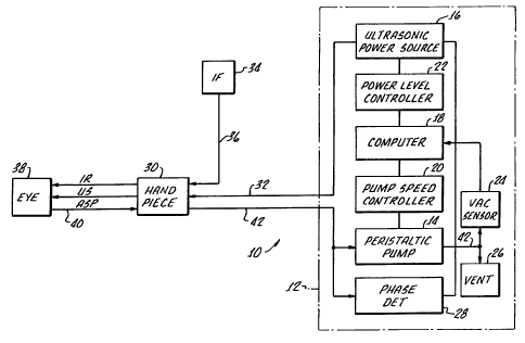
Figure 1 is a functional block diagram of a
phacoemulsification system in accordance with the present
invention;
Figure 2 is a functional block diagram of an
alternative embodiment of a phacoemulsification system in
accordance with the present invention which includes
apparatus for providing irrigation fluid at more than one
pressure to a handpiece;
Figure 3 is a flow chart illustrating the operation
of the occluded-unoccluded mode of the
phacoemulsification system with variable aspiration
rates;
Figure 4 is a flow chart illustrating the operation
of the occluded-unoccluded mode of the
phacoemulsification system with variable ultrasonic power
levels;
Figure 5 is a flow chart illustrating the operation
of the variable duty cycle pulse function of the
phacoemulsification system;
Figure 6 is a flow chart illustrating the operation
of the occluded-unoccluded mode of the
phacoemulsification system with variable irrigation
rates;
Figure 7 is a plot of the 90 degree phase shift
between the sine wave representation of the voltage
applied to a piezoelectric phacoemulsification handpiece
and the resultant current into the handpiece;
11
CA 02434480 2003-07-11
WO 02/056806 PCT/US02/00471
Figure 8 is a plot of the phase relationship and the
impedance of a typical piezoelectric phacoemulsification
handpiece;
Figure 9 is a block diagram of improved phase
detector circuitry suitable for performing a method in
accordance with the present invention;
Figure 10 is a plot of phase relationship as a
function of frequency for various handpiece/needle
loading;
Figure 11 is a function block diagram of a phase
control phacoemulsification system utilizing phase angles
to control handpiece/needle parameters with max phase
mode operation;
Figure 12 is a function block control diagram of a
phase control phacoemulsification system utilizing phase
angles to control handpiece/needle parameters with a load
detect method; and
Figure 13 is a function block control diagram of a
pulse control phacoemulsification system.
DETAILED DESCRIPTION OF THE DRAWINGS
Turning now to the drawings, and particularly to
Figure 1 thereof, there is shown, in functional block
diagram form, a phacoemulsification system indicated
generally by the reference numeral 10. The system has a
control unit 12, indicated by the dashed lines in Figure
1 which includes a variable speed peristaltic pump 14,
which provides a vacuum source, a source of pulsed
ultrasonic power 16, and a microprocessor computer 18
12
CA 02434480 2003-07-11
WO 02/056806 PCT/US02/00471
that provides control outputs to pump speed controller 20
and ultrasonic power level controller 22. A vacuum
sensor 24 provides an input to computer 18 representing
the vacuum level on the output side of peristaltic pump
14. Suitable venting is provided by vent 26.
As hereinafter described in greater detail, a phase
detector 28 provides an input to computer 18 representing
a phase shift between a sine wave representation of the
voltage applied to a handpiece/needle. 30 and the
resultant current into the handpiece 30. The block
representation of the handle 30 includes a typical
handpiece having a needle and electrical means, typically
a piezoelectric crystal, for ultrasonically vibrating the
needle.
The control unit 12 supplied ultrasonic power on
line 32 to a phacoemulsification handpiece/needle 30. An
irrigation fluid source 34 is fluidly coupled to
handpiece/needle 30 through line 36. The irrigation
fluid and ultrasonic power are applied by
handpiece/needle 30 to a patient's eye which is indicated
diagrammatically by block 38. Aspiration of the eye 38
is achieved by means of the control unit peristaltic pump
14 through lines 40 and 42. A switch 43 disposed on the
handpiece 30 may be utilized as a means for enabling a
surgeon to select an amplitude of electrical pulses to
the handpiece via the computer 18, power level controller
22 and ultrasonic power source 16 as hereinafter
discussed. It should be appreciated that any suitable
input means, such as, for example, a foot pedal (not
shown) may be utilized in lieu of the switch 43.
The computer 18 responds to preset vacuum levels in
output line 42 from peristaltic pump 14 by means of
13
CA 02434480 2003-07-11
WO 02/056806 PCT/US02/00471
signals from the previously mentioned vacuum sensor 24.
Operation of the control unit in response to the
occluded-unoccluded condition of handpiece 30 is shown in
the flow diagram of Figure 3.
As shown in Figure 3, if the handpiece aspiration
line 40 is occluded, the vacuum level sensed by vacuum
sensor 24 will increase. The computer 18 has operator-
settable limits for aspiration rates, vacuum levels and
ultrasonic power levels. As illustrated in Figure 3,
when the vacuum level sensed by vacuum sensor 24 reaches
a predetermined level as a result of occlusion of the
handpiece aspiration line 40, computer 18 instructs pump
speed controller 20 to change the speed of the
peristaltic pump 14 which, in turn, changes the
aspiration rate. It will be appreciated that, depending
upon the characteristics of the material occluding
handpiece/needle 30, the speed of the peristaltic pump 14
can either be increased or decreased. When the occluding
material is broken up, the vacuum sensor 24 registers a
drop in vacuum level, causing computer 18 to change the
speed of peristaltic pump 14 to an unoccluded operating
speed.
In addition to changing the phacoemulsification
parameter of aspiration rate by varying the speed of the
peristaltic pump 14, the power level of the ultrasonic
power source 16 can be varied as a function of the
occluded or unoccluded condition of handpiece 30. Figure
4 illustrates in flow diagram form the control of the
ultrasonic power source power level by means of computer
18 and power level controller 22. It will be appreciated
that the flow diagram of Figure 4 corresponds to the flow
diagram of Figure 3 but varies the phacoemulsification
parameter of the ultrasonic power level.
14
CA 02434480 2003-07-11
WO 02/056806 PCT/US02/00471
With reference to Figure 5, there is shown a flow
diagram depicting the control of the ultrasonic power
source 16 to produce varying pulse duty cycles as a
function of selected power levels. As shown in Figure 5,
and by way of illustration only, a 33% pulse duty cycle
is run until the power level exceeds a preset threshold;
in this case, 33%. At that point, the pulse duty cycle
is increased to 50% until the ultrasonic power level
exceeds a 50% threshold, at which point the pulse duty
cycle is increased to 66%. When the ultrasonic power
level exceeds 66% threshold, the power source is run
continuously, i.e., a 100% duty cycle. Although the
percentages of 33, 50 and 66 have been illustrated in
Figure 5, it should be understood that other percentage
levels can be selected to define different duty cycle
shift points.
With reference to Figure 13, when the computer 18
has been enabled for pulse mode operation by an amplitude
input via the switch 43, the use of thermal tissue damage
is reduced. In accordance with the present invention,
very rapid pulse duration is provided with adequate
energy to cut the tissue with kinetic or mechanical
energy but then the pulse is turned off long enough to
eliminate the thermal BTU's before the next pulse is
activated. A surgeon may vary the pulse amplitude in a
linear manner via the switch 43 and the control unit in
response to the selected pulse amplitude, irrigation and
aspiration fluid flow rates, controlling a pulse duty
cycle. As hereinabove noted, an off duty duration or
cycle is provided to ensure heat dissipation before a
subsequent pulse is activated. In this way, increase
amplitude will increase tip acceleration and thus BTU's
for tissue damaging heat generation. That is, the
CA 02434480 2003-07-11
WO 02/056806 PCT/US02/00471
surgeon can use linear power control to select the
correct acceleration necessary to cut through the tissue
density while the control unit provides a corresponding
variation in pulse width and "Off time" to prevent tissue
de-compensation from heat. The control unit is
programmed depending on the phaco handpiece chosen (total
wattage) or the phaco tip (dimensions, weight). This use
of rapid pulsing is similar to how lasers operate with
very short duration pulses. Pulses may have a repetition
rate of between about 25 and 2000 pulses per second.
Turning back to Figure 2, there is shown an
alternative embodiment 50 of a phacoemulsification
system, in accordance with the present invention, and
which incorporates all of the elements of the system 10
shown in Figure 1, with identical reference characters
identifying components, as shown in Figure 1.
In addition to the irrigation fluid source 34, a
second irrigation fluid source 35 is provided with the
sources 34, 35 being connected to the line 36 entering
the handpiece/needle 30 through lines 34a, 35a,
respectively, and to a valve 38. The valve 38 functions
to alternatively connect line 34a and source 34 and line
35a and source 35 with the handpiece/needle 30 in
response to a signal from the power level controller 22
through a line 52.
As shown, irrigation fluid sources 34, 35 are
disposed at different heights above the handpiece/needle
30 providing a means for introducing irrigation fluid to
the handpiece at a plurality of pressures, the head of
the fluid in the container 35 being greater than the
head of fluid in the container 34. A harness 42,
including lies of different lengths 44, 46, when
16
CA 02434480 2008-08-20
WO 02/056806 PCT/US02/00471
connected to the support 48, provides a means for
disposing the containers 34, 35 at different heights over
the handpiece/needle 30.
The use of containers for irrigation fluids at the
various heights is representative of the means for
providing irrigation fluids at different pressures, and
alternatively, separate pumps may be provided with, for
example, separate circulation loops (not shown) which
also can provide irrigation fluid at discrete pressures
to the handpiece/needle 30 upon a command from the power
controller 22.
With reference to Figure 5, if the handpiece
aspiration line 40 is occluded, the vacuum level sensed
by the vacuum sensor 24 will increase. The computer 18
has operator-settable limits for controlling which of the
irrigation fluid supplies '34,35 will be connected to the
handpiece 30. It should be appreciated that while two
irrigation fluid sources, or containers 32, 33 are shown,
any number of containers may be utilized.
As shown in Figure 6, when the vacuum level by the
vacuum sensor 24 reaches a predetermined level, as a
result of occlusion of the aspiration handpiece line 40,
the computer controls the valve 38 causing the valve to
control fluid communication between each of the
containers 34, 35 and the handpiece/needle 30.
It should be appreciated that, depending upon the
characteristics of the material occluding the
handpiece/needle 30, as hereinabove described and the
needs and techniques of the physician, the pressure of
irrigation fluid provided the handpiece may be increased
or decreased. As occluded material 24, the vacuum sensor
17
CA 02434480 2003-07-11
WO 02/056806 PCT/US02/00471
24 registers a drop in the vacuum level causing the
valve 38 to switch to a container 34, 35, providing
pressure at an unoccluded level.
As noted hereinabove, it should be appreciated that
more than one container may be utilized in the present
invention, as an additional example, three containers
(not shown) with the valve interconnecting to select
irrigation fluid from any of the three containers, as
hereinabove described in connection with the Figure 1A
container system.
In addition to changing phacoemulsification
handpiece/needle 30 parameter as a function of vacuum,
the occluded or unoccluded state of the handpiece can be
determined based on a change in load sensed by a
handpiece/needle by way of a change in phase shift or
shape of the phase curve.
The typical range of frequencies used for
phacoemulsification handpiece 30 is between about 30 kHz
and about 50 kHz. When the frequency applied to the
handpiece is significantly higher, or lower than
resonancy, it responds electrically as a capacitor. The
representation of this dynamic state is shown in Figure 7
in which curve 60 (solid line) represents a sine wave
corresponding to handpiece 30 current and curve 62
(broken line) represents a sine wave corresponding to
handpiece 30 voltage.
The impedance of the typical phacoemulsification
handpiece 30 varies with frequency, i.e., it is reactive.
The dependence of typical handpiece 30 phase and
impedance as a function of frequency is shown in Figure 8
in which curve 64 represents the phase difference between
18
CA 02434480 2003-07-11
WO 02/056806 PCT/US02/00471
current and voltage of the handpieces function frequency
and curve 66 shows the change in impedance of the
handpiece as a function of frequency. The impedance
exhibits a low at "Fr" and a high "Fa" for a typical
range of frequencies.
Automatic tuning of the handpiece, as hereinabove
briefly noted, is typically accomplished by monitoring
the handpiece electrical signals and adjusting the
frequency to maintain a consistency with selected
parameters.
In order to compensate for a load occurring at the
tip of the phacoemulsification handpiece, the drive
voltage to the handpiece can be increased while the load
is detected and then decreased when the load is removed.
This phase detector is typically part of the controller
in this type of system.
In such conventional phase detectors, the typical
output is a voltage as proportional to the difference in
alignment of the voltage and the current waveform, for
example, -90 degrees as shown in Figure 7. As shown in
Figure 8, it is important to consider that during the use
of the handpiece, the waveform is varying in phase and
correspondingly the output waveform is also varying.
Heretofore, the standard technique for measuring
electrical phase has been to read a voltage that is
proportional to phase and also to frequency. This type
of circuit can be calibrated for use with a single
frequency as changing the frequency would cause the
calibration data to be incorrect.
19
CA 02434480 2003-07-11
WO 02/056806 PCT/US02/00471
This can also be seen with single frequency systems.
The corrected phase value will draft due to variation in
the circuit parameters.
The other typical approach is to utilize a
microprocessor to compare the value of the phase detector
output with that of a frequency detector and compute the
true phase. This approach is fairly complex and is
subject to drift of the individual circuits as well as
resolution limitations.
A block diagram 70 as shown in Figure 9 is
representative of an improved phase detector suitable for
performing the method in accordance with the present
invention. Each of the function blocks shown comprises
conventional state-of-the-art circuitry of typical design
and components for producing the function represented by
each block as hereinafter described.
The voltage input 72 and current 74 from a
phacoemulsification handpiece 30 is converted to an
appropriate signal using an attenuator 76 on the voltage
signal to the phacoemulsification handpiece, and a
current sense resistor 78 and fixed gain amplifier for
the handpiece 30 current.
Thereafter, an AC voltage signal 80 and AC current
signal 82 is passed to comparators 84, 86 which convert
the analog representations of the phacoemulsification
voltage and current to logic level clock signals.
The output from the comparator 84 is fed into a D
flip flop integrated circuit 90 configured as a frequency
divide by 2. The output 92 of the integrated circuit 90
is fed into an operational amplifier configured as an
CA 02434480 2003-07-11
WO 02/056806 PCT/US02/00471
integrator 94. The output 96 of the integrator 94 is a
sawtooth waveform of which the final amplitude is
inversely proportional to the handpiece frequency. A
timing generator 98 uses a clock synchronous with the
voltage signal to generate A/D converter timing, as well
as timing to reset the integrators at the end of each
cycle.
This signal is fed into the voltage reference of an
A/D converter via line 96.
The voltage leading edge to current trailing edge
detector 100 uses a D flip flop integrated circuit in
order to isolate the leading edge of the handpiece
voltage signal. This signal is used as the initiation
signal to start the timing process between the handpiece
30 voltage and handpiece 30 current.
The output 102 of the leading detector 100 is a
pulse that is proportional to the time difference in
occurrence of the leading edge of the handpiece 30
voltage waveform and the falling edge of the handpiece
current waveform.
Another integrator circuit 104 is used for the
handpiece phase signal 102 taken from the detector 100.
The output 106 of the integrator circuit 104 is a
sawtooth waveform in which the peak amplitude is
proportional to the time difference in the onset of
leading edge of the phacoemulsification voltage and the
trailing edge of the onset of the handpiece current
waveform. The output 106 of the integrator circuit 104
is fed into the analog input or an A/D (analog to
digital converter) integrated circuit 110.
21
CA 02434480 2008-08-20
WO 02/056806 PCT/US02/00471
Therefore, the positive reference input 96 to the
A/D converter 110 is a voltage that is inversely
proportional to the frequency of operation. The phase
voltage signal 96 is proportional to the phase difference
between the leading edge of the voltage onset, and the
trailing edge of the current onset, as well as inversely
proportional to the frequency of operation. In this
configuration, the two signals Frequency voltage
reference 96 and phase voltage 46' track each other over
the range of frequencies, so that the output of the A/D
converter 110 produces the phase independent of the
frequency of operation.
The advantage of utilizing this approach is that the
system computer 18 (see Figures 1 and 2) is provided with
a real time digital phase signal that 0 to 255 counts
will consistently represent 0 to 359 degrees of phase.
The significant advantage is that no form of
calibration is necessary since the measurements are
consistent despite the frequencies utilized.
For example, using AMPs operation frequencies of 38
kHz and 47 kHz and integrator having a rise time of 150 x
103V/2 and an 8 bit A/D converter having 256 counts, a
constant ratio is maintained and variation in frequency
does not affect the results. This is shown in the
following examples.
EXAMPLE 1 - 38 KHz OPERATION:
Period of 1 clock cycle = 1/F @ 38KHz=26.32 x 10-65
Portion of one period for I
= 90 degrees = 26.32 x 10⁻⁶S /4=6.59 x 10'6S
Integrator output for one reference cycle
_(150 x 10-3 V/S)x(26.32 x 10-6S)=3.95 Volts
22
CA 02434480 2003-07-11
WO 02/056806 PCT/US02/00471
Integrator output from 90 degree cycle duration
= (150) x 103 V/S)x(6.59 x 10-6S)= .988 Volts
Resulting Numerical count from A/D converter
= 3.95 Volts/256 counts = .0154 Volts per count
Actual Number of A/C counts for 90 degrees at 38 KHz
EXAMPLE 2 - 47 KHz OPERATION:
Period of 1 clock cycle - 1/F @ 47KHz=21.28 x 10⁻⁶S
Integrator output for one reference cycle
= (150 x 103 V/S) x (21.28 x 10⁻⁶S) = 3.19 Volts
Integrator output from 90 degree cycle duration
= (150 x 103 V/S)x(5.32 x 1010-6S) = .798 Volts
Resulting Numerical count from A/D converter
= 3.19 Volts/256 counts = .0124 Volts per count
Actual Number of A/D counts for 90 degrees at 47 KHz
=.798/.0124=64 counts
A plot of phase angle as a function of frequency is
shown in Figure 10 for various handpiece 30 loading, a no
load (max phase), light load, medium load and heavy load.
With reference to Figure 11, representing max phase
mode operation, the actual phase is determined and
compared to the max phase. If the actual phase is equal
to, or greater than, the max phase, normal aspiration
function is performed. If the actual phase is less than
the max phase, the aspiration rate is changed, with the
change being proportionate to the change in phase.
Figure 12 represents operation at less than max load
in which load (see Figure 10) detection is incorporated
into the operation, a method of the present invention.
As represented in Figure 11, representing max phase
mode operation, if the handpiece aspiration line 40 is
occluded, the phase sensed by phase detector sensor 28
23
CA 02434480 2003-07-11
WO 02/056806 PCT/US02/00471
will decrease (see Figure 10) The computer 18 has
operator-settable limits for aspiration rates, vacuum
levels and ultrasonic power levels. As illustrated in
Figure 11, when the phase sensed by phase detector 28
reaches a predetermined level as a result of occlusion of
the handpiece aspiration line 40, computer 18 instructs
pump speed controller 20 to change the speed of the
peristaltic pump 14 which, in turn, changes the
aspiration rate.
It will be appreciated that, depending upon the
characteristics of the material occluding
handpiece/needle 30, the speed of the peristaltic pump 14
can either be increased or decreased. When the occluding
material is broken up, the phase detector 28 registers an
increase in phase angle, causing computer 18 to change
the speed of peristaltic pump 14 to an unoccluded
operating speed.
In addition to changing the phacoemulsification
parameter of aspiration rate by varying the speed of the
peristaltic pump 14, the power level and/or duty cycle of
the ultrasonic power source 16 can be varied as a
function of the occluded or unoccluded condition of
handpiece 30.
Although there has been hereinabove described a
method and apparatus for controlling a
phacoemulsification handpiece utilizing the voltage
current phase relationship of the piezoelectric
phacoemulsification handpiece in accordance with the
present invention, for the purpose of illustrating the
manner in which the invention may be used to advantage,
it should be appreciated that the invention is not
limited thereto. Accordingly, any and all modifications,
24
CA 02434480 2003-07-11
WO 02/056806 PCT/US02/00471
variations, or equivalent arrangements which may occur to
those skilled in the art, should be considered to be
within the scope of the present invention as defined in
the appended claims.