Note: Descriptions are shown in the official language in which they were submitted.
CA 02434519 2003-07-11
WO 02/056942 PCT/US02/05126
-1-
MODULAR ENDOSCOPE VALVE ASSEMBLY AND METHOD
CROSS REFERENCE TO RELATED APPLICATION
This application is a continuation-in-part of co-pending U.S. Patent
application Serial No. 091761,784, filed January 17, 2001, the entirety of
which
is hereby incorporated by reference.
BACKGROUND
The present invention relates to endoscopic surgical devices, and in
particular to valve assemblies used to control the flow of irrigation fluid in
such
devices.
Endoscopic devices are customarily provided with an irrigation port that
conducts an irrigation liquid to the viewing area at the end of the endoscopic
device. One prior-art approach is to pressurize irrigation fluid in an IV
fluid
bag, and then to supply the pressurized irrigation fluid directly into an
endoscope such as a ureteroscope. The endoscope includes integral valves
that are generally operated with one hand while the other hand holds the
handpiece of the endoscope. The advantage of this system is that the
irrigation fluid is pressurized, thereby providing dilation of a ureter and
good
visibility. One potential disadvantage with this type of irrigating system is
that
it may be difficult to control fluid flow since two hands are required. If the
fluid
flow is not controlled properly, a stone can be dislodged back into the middle
or upper ureter by an excessively high rate of flow. Also, in the event of
extravasation, uncontrolled amounts of fluid can flow into the
retroperitoneum.
Another type of irrigation system is a hand-operated, pressurized
irrigating system commercially manufactured by Bard, Boston Scientific, and
ACMI. This approach allows the amount of fluid being injected to be
controlled, but the apparatus is relatively bulky. This system is mounted
separately from the ureteroscope, and separate hands are used to hold the
handpiece of the ureteroscope and to control the flow of irrigation fluid. On
occasion, an assistant controls fluid flow while the physician holds the
endoscope in the left hand and performs an endoscopic procedure with the
CA 02434519 2003-07-11
WO 02/056942 PCT/US02/05126
-2-
right hand. In this case, precise control of the rate of fluid flow is
difficult,
because oral instructions are slower and less precise than direct manual
control by the physician.
A third type of irrigation system includes two or more syringes that are
operated by an assistant one at a time to supply pressurized irrigation fluid
to
the endoscopic device. Generally a valve is provided that allows the assistant
to fill one of the syringes while the other is in use.
A fourth type of irrigation system includes a roller pump mechanism
that delivers irrigation fluid at a constant set pressure. This system may
~ incorporate a blow-off valve to prevent excessive pressure, and it is
generally
used in endoscopic specialties such as orthopedics in performing
arthroscopies. This system requires the use of an electric motor and
controller, and it is therefore costly and bulky.
Goodman U.S. Patent 4,567,880 discloses an endoscopic device
having a three-way valve forming a permanent portion of the handpiece of the
endoscope. This system allows a physician to control the flow of irrigation
fluid with the same hand as that used to hold the handpiece. However, the
Goodman system requires a specially constructed endoscope, and the
irrigation system is an integral part of the endoscope. This limits the
irrigation
system to use with one particular endoscope.
The present invention is directed to an improved system and method
for controlling the flow of irrigation fluid in an endoscopic device.
SUMMARY
The preferred embodiment described below includes a modular valve
assembly having a housing that carries an inlet port, an outlet port and a
valve. The valve can be manually controlled by a user with the hand holding
the endoscope to selectively allow or block fluid flow from the inlet port to
the
outlet port.
In use, the housing is releasably mounted to the handpiece of an
endoscope by a pressure-sensitive adhesive, strap, or other fastener. The
inlet port is connected to a source of pressurized irrigation fluid and the
outlet
CA 02434519 2003-07-11
WO 02/056942 PCT/US02/05126
-3-
port is connected to the irrigation port of the endoscope. The physician can
then use a single hand to perform moth the function of holding the handpiece
and the function of controlling the flow of irrigation fluid. Typically, the
physician holds the handpiece in the palm, using the thumb and fingers of one
hand. The physician controls the flow of irrigation fluid with one finger of
the
hand that is holding the handpiece. This leaves the other hand free for
performing a surgical procedure via the working port of the endoscope, e.g.,
positioning and manipulating a stone extraction basket. Once the surgical
procedure is completed, the modular housing can simply be removed from the
endoscope and discarded. This eliminates the need to clean the valve or the
ports of the valve assembly.
The housing may be formed in one or more parts, and it may include a
second valve to allow the physician to control the application of suction in
addition to the flow of irrigation fluid.
This section has been provided by way of general introduction, and it
should not be used to narrow the scope of the following claims.
BRIEF DESCRIPTION OF THE DRAWINGS
Figure 1 is a perspective view of a ureteroscope on which is mounted a
modular valve assembly.
Figure 2 is a top perspective view of the valve assembly of Figure 1,
prior to mounting on the ureteroscope.
Figure 3 is a bottom perspective view of the valve assembly of
Figure 2.
Figure 4 is a perspective view of the valve assembly of Figures 2 and 3
connected to a source of pressurized irrigation fluid.
Figures 5 and 6 are schematic views showing the valve of the valve
assembly of Figures 1-3 in the opened and closed positions, respectively.
Figures 7 and 8 are schematic views of an alternative, rotary-motion
valve in the opened and closed positions, respectively.
Figure 9 is a fragmentary sectional view of another modular valve
assembly of this invention mounted on a ureteroscope.
CA 02434519 2003-07-11
WO 02/056942 PCT/US02/05126
-4-
Figure 10 is a fragmentary sectional view of yet another modular valve
assembly of this invention.
Figure 11 is a fragmentary sectional view of the ureteroscope of
Figure 10 and a cover plate.
Figure 12 is a fragmentary sectional view of another modular valve
assembly of this invention mounted on a ureteroscope.
Figure 13 is a cross-sectional view of another modular valve assembly
of this invention including a mechanical latch to hold the valve in a selected
position.
Figures 14, 15 and 16 are three sectional views of another modular
valve assembly of this invention in three different positions.
Figure 17 is a sectional view of another modular valve assembly of this
invention.
Figures 18, 19 and 20 are side views of three additional modular valve
assemblies of this invention.
DETAILED DESCRIPTION OF THE PRESENTLY PREFERRED
EMBODIMENTS
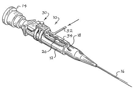
Turning now to the drawings, Figure 1 is a perspective view of an
endoscopic device 10 that in this embodiment is a ureteroscope. The
ureteroscope 10 includes a handpiece 12 that carries an eyepiece 14 at one
end and a shaft 16 at the other end. An irrigation port 18 is carried by the
handpiece 12, and irrigation fluid introduced via the irrigation port 18 is
conducted to the viewing area at the end of the shaft 16 that is inserted into
the patient. The handpiece 12 also defines an exterior surface 20.
The endoscopic device 10 can take any suitable form, and the present
invention is not limited to any particular embodiment. For example, the
endoscopes of any of the following U.S. Patents can be adapted for use with
this invention: Waflace U.S. Patent 2,691,370, Ibe U.S. Patent 4,132,227,
Goodman U.S. Patent 4,567,880, Cho U.S. Patent 5,083,549, Muller U.S.
Patent 5,199,417, Bonati U.S. Patent 5,290,279, and Odanacka U.S. Patent
5,830,126. Conventional endoscopes such as the ureteroscopes
CA 02434519 2003-07-11
WO 02/056942 PCT/US02/05126
-5-
manufactured by ACMI, Wolf, Olympus and Storz are also well-adapted for
use with this invention. This list is intended only by way of illustration, in
the
widest variety of ureteroscopes, arthroscopes, laparoscopes, hysteroscopes,
sinuscopes, and endoscopes adapted for other specialties can be used with
this invention, including flexible, semi-rigid, and rigid endoscopes.
In use, the physician holds the handpiece with one hand, thereby
presenting the eyepiece for viewing and positioning the shaft as desired. The
other hand is typically used to manipulate surgical tools introduced into the
patient via the working port on the shaft. As shown in Figure 1, a modular
endoscope valve assembly 30 is releasably secured to the handpiece 12.
This valve assembly 30 is shown in greater detail in Figures 2 and 3, and it
includes an inlet port 32 and an outlet port 34. In use the inlet port 32 is
releasably connected to a source of pressurized irrigation fluid, and the
outlet
port 34 is releasably connected to the irrigation port 18 of the handpiece.
The valve assembly 30 includes a valve that is interposed between the
inlet port 32 and the outlet port 34 and is controlled by a valve actuator 38.
The valve assembly 30 also includes a housing 50 that includes a mounting
surface 52. The mounting surface 52 carries a pressure-sensitive adhesive
40 initially covered by a release paper 46. The housing 50 also supports a
pair of straps 42 that include respective hook-and-loop fasteners 44. A
contrast-introduction port 48 is provided in fluid communication with the
outlet
port 34. Check valves, not shown, can be provided to prevent flow from the
outlet port 34 to the contrast-introduction port 48 and vice-versa.
Figure 4 shows the manner in which the inlet port 32 of the valve
assembly 30 can be releasably connected to a source of pressurized irrigation
fluid, in this case contained within an IV bag 60. The IV bag 60 is disposed
within a pressure cuff 62 that can be inflated with an inflator 64 to a
pressure
indicated by a pressure gauge 66. Standard Luer-lock fittings can be used to
connect the inlet port 32 to a tube 68 that is in turn connected to the IV bag
60. The IV bag contains a conventional irrigation fluid, which is pressurized
by inflating the pressure cuff 62 to a desired pressure with the inflator 64.
CA 02434519 2003-07-11
WO 02/056942 PCT/US02/05126
-6-
Figures 5 and 6 show two schematic views of the valve 36 of the valve
assembly 30. In Figure 5 the valve actuator 38 is depressed and the valve 36
allows fluid flow from the inlet port 32 to the outlet port 34. When manual
pressure is removed from the valve actuator 38, the valve 36 returns to the
position of Figure 6, in which the valve 36 blocks the flow of fluid between
the
inlet and the outlet ports 32, 34. Alternatively, the valve 38 may be arranged
such that fluid flow is blocked when the actuator 38 is depressed and
unblocked when the actuator 38 is released.
The valve 36 of Figures 5 and 6 is a linear valve that slides along a
linear axis between the opened position of Figure 5 and the closed position of
Figure 6. Other types of valves are suitable, including the linear valve of
U.S.
Patent 4,238,108 and the rotary valve 80 of Figures 7 and 8. A rotary valve
80 rotates about an axis between the opened position of Figure 7 and the
closed position of Figure 8, and the associated valve actuator (not shown in
Figures 7 and 8) moves in a rotary motion as well.
In use, the valve assembly 30 is distributed separately from the
endoscope 10. In this embodiment, the valve assembly 30 is shaped to fit on
a wide variety of endscopes 10 such that the endoscope 10 does not have to
be specially shaped or configured for the valve assembly 30. Prior to an
endoscopic procedure, the release paper 46 is removed, thereby exposing the
pressure-sensitive adhesive 40 on the mounting surface 52. Then the valve
assembly 30 is placed on the exterior surface 20 of the endoscope 10, and
the~pressure-sensitive adhesive 40 releasably holds the valve assembly 30 in
place. The straps 42 are positioned around the handpiece 12, and the hook-
and-loop fasteners 44 are secured together to hold the valve assembly 30 in
place.
Either before or after the valve assembly 30 is secured to the
handpiece 12, the inlet port 32 is releasably secured to the tube 68 (Figure
4)
and the outlet port 34 is releasably secured to the irrigation port 18 of the
handpiece 12 (Figure 1 ). Preferably, the valve assembly 30 is flushed after
it
is connected to the tube 68 and before it is connected to the irrigation port
18.
CA 02434519 2003-07-11
WO 02/056942 PCT/US02/05126
-7-
The physician then performs the desired endoscopic procedure, using
a single hand both to hold the handpiece 12 and to control the flow~of
pressurized irrigation fluid with the valve assembly 30. A part of the hand
that
holds the handpiece (e.g. the fingers or the heel) is used to move the valve
actuator.
Once the endoscopic procedure has been completed, the valve
assembly 30 can simply be removed from the endoscope 10 by releasing the
hook-and-loop fasteners 44 and lifting or twisting the valve assembly 10 away
from the handpiece 12 until the pressure-sensitive adhesive 40 releases.
The valve assembly 30 described above uses both a pressure-
sensitive adhesive and a set of straps to releasably secure the valve
assembly 30 in place on the handpiece 12. In alternative embodiments the
adhesive may be used without the reinforcing straps, or the reinforcing straps
can be used without the adhesive. The strap may be varied widely. For
example, the strap may pass over the top of the valve assembly, and the
a
actuator may pass through an opening in the strap. The strap may be fixed to
the valve assembly or not. Also, other types of fasteners can be used to
releasably hold the valve assembly in place on the endoscope.
Figure 9 shows a second preferred embodiment 90 of the modular
valve assembly of this invention. The valve assembly 90 is identical to the
valve assembly 30 described above except for the manner of releasably
attaching the valve assembly 90 to the handpiece 12'. In this case the valve
assembly 90 is provided with mechanical fasteners 92 and the handpiece 12'
is provided with mating mechanical fasteners 94 such that the valve assembly
90 can be snapped in place on the handpiece 12' and removed from the
handpiece 12' as desired. In this example, the fasteners 92 take the form of
protruding studs and the mating fasteners 94 take the form of recesses
shaped to receive the fasteners 92 in a snap-lock action.
Figure 10 shows portions of a third valve assembly 100 which is similar
to that of Figure 9 except that the fasteners 102 are shaped as recesses and
the mating fasteners 104 are shaped as protruding studs that fit into the
fasteners' 102 in a snap-lock manner.
CA 02434519 2003-07-11
WO 02/056942 PCT/US02/05126
_g_
Figure 11 shows the handpiece 12" of Figure 10 with a cover 110
snapped in place on the mating fasteners 104. The cover 110 covers the
mating fasteners 104 when a valve assembly is not in place on the handpiece
12" .
Figure 12 shows another modular valve assembly 120 mounted in
place on the handpiece 12 of an endoscopic device. The valve assembly 120
includes an actuator 122, an inlet port 124, and an outlet port 126. The valve
assembly 120 is mounted on a base 130, and the base 130 supports a spring
clip 128 that is designed to fit at least partially around the handpiece 12
and to
releasably hold the base 130 and therefore the valve assembly 120 in position
on the hand-piece 12. The spring clip 128 is another example of a
mechanical fastener that is suitable for releasably securing a modular valve
assembly to an endoscopic device. In this example, the outer surface of the
handpiece 12 can be considered a mating fastener that cooperates with the
spring clip 128 to releasably hold the valve assembly 120 in place on the
endoscopic device. The details of construction of the modular valve assembly
120 can be varied widely, in accordance with any of the other valve
assemblies described in this specification.
Figure 13 provides a sectional view of another modular valve assembly
140. The modular valve assembly 140 includes a housing 142 that supports
an inlet port 144 and an outlet port 146. A valve element 148 is slidably
received in a cylinder defined by the housing 142, and the valve element 148
defines an annular recess 150. The annular recess 150 completely encircles
the valve element 148, and thereby provides an interconnecting flow path
between the inlet port 144 and the outlet port 146 when the recess 150 is
aligned with the ports 144, 146. The valve element 148 is biased to the upper
position shown in Figure 13 by a spring 152. The valve assembly 140
includes an actuator 156 that can be pressed downwardly by a finger of the
user. A latch 154 is interposed between the actuator 156 and the valve
element 148, and the latch 154 operates to hold the valve element 148 in a
selected position.
CA 02434519 2003-07-11
WO 02/056942 PCT/US02/05126
_g_
In use, the inlet port 144 is coupled to a source of irrigation fluid and
the outlet port 146 is coupled to the irrigation port of an endoscopic device.
In the position shown in Figure 13, the recess 150 is out of alignment with
the
inlet and outlet ports 144, 146, and no irrigation fluid is passed to the
outlet
port 146. When the user presses the actuator 156 downwardly in the view of
Figure 13, the recess 150 comes into alignment with the inlet and outlet ports
144, 146, thereby permitting irrigation liquid to flow to the endoscopic
device.
Further downward movement of the actuator 156 causes the latch 154 to
hold the valve element 148 in a position in which the recess 150 is aligned
with the inlet and outlet ports 144, 146. Once the latch 154 is engaged, the
user can take his or her hand off of the actuator 156, and high volume flow of
irrigation fluid is maintained from the inlet port 144 to the outlet port 146.
In order to stop the flow of irrigation fluid, the user again depresses the
actuator 156, thereby causing the latch 154 to release the valve element 148
to move upwardly, back to the position of Figure 13.
The valve assembly 140 allows the user to modulate the flow of
irrigation fluid as described above as he or she gradually depresses the
actuator 156. The latch 154 also allows the user to latch the valve in the
open
position, until it is released by the user.
Many alternative structures can be used for the latch 154. For
example, the latch 154 can be constructed like the latch mechanism
conventionally used with retractable ballpoint pens. Such latch mechanisms
respond to first depression of the actuator by latching the latched element
down, and they respond to a next depression of the actuator by allowing the
latched element to move upwardly. This is only one example, and many
alternatives are possible.
Figures 14, 15 and 16 provide three views of another modular valve
assembly 160 that can be used as described above. As best shown in
Figure 14, the modular valve assembly 160 includes a housing 162 that
supports a valve element 164 for sliding movement. The valve element 164
defines two spaced, annular recesses 166, 168, and the upper end of the
CA 02434519 2003-07-11
WO 02/056942 PCT/US02/05126
-10-
valve element 164 forms an actuator 170. The valve element 164 is biased to
the upper position shown in Figure 14 by a spring 178.
The housing 162 supports first and second inlet ports 172, 174 and
aligned tubes 173, 175 that are connected to an outlet port 176. The first
inlet
port 172 in use is connected to a liquid source, such as a source of
irrigation
fluid. The second inlet port 174 in use is connected to a suction source, such
as a partial vacuum. The outlet port 176 in use is connected to an irrigation
port of an endoscopic device. Check valves, not shown, may be used to
prevent flow from the tube 173 to the tube 175 and vice-versa.
In the rest position of Figure 14, the valve element 164 isolates both
the first and second inlet ports 172, 174 from the outlet port 176. This is
because the first inlet port 172 is out of alignment with the first recess
166,
and the second inlet port 174 is out of alignment with the second recess 168.
Figure 15 shows the valve assembly 160 in a second position, in which
the user has depressed the actuator 170, thereby compressing the spring 178
and bringing the first recess 166 into alignment with the first inlet port 172
and
the tube 173. In this position, irrigation fluid from the liquid source is
passed
by the assembly 160 to the outlet port 176.
As shown in Figure 16, when the actuator 170 is further depressed, the
first recess 166 is moved out of alignment with the first inlet port 172, and
the
second recess 168 is moved into alignment with the second inlet port 174. In
this position, the valve assembly 160 allows suction from the suction source
to
pass via the second inlet port 174 and the second tube 175 to the outlet port
176.
The modular valve assembly 160 of Figures 14 through 16 is intended
to be removably attached to the handpiece of an endoscopic device, all as
described above. Any of the mechanisms described above for releasably
securing the valve assembly to the handpiece can be used. The valve
assembly 160 provides all of the functions described above regarding the
valuing of irrigation fluid from the liquid source to the outlet port 176. In
addition, the valve assembly 160 allows the physician efficiently and easily
to
introduce suction to the endoscopic device by moving the actuator 170 to the
CA 02434519 2003-07-11
WO 02/056942 PCT/US02/05126
-11-
fully depressed position of Figure 16. Thus, a single valve assembly controls
both the introduction of irrigation fluid and the application of suction to
the
irrigation port of the endoscopic device.
The valve assembly 1.60 utilizes a linear slide valve to implement the
valuing functions described above. It should of course be understood that this
invention is not limited to such linear slide valves, and that the widest
variety
of valve mechanisms can be used to perform these valuing functions.
Figure 17 shows a sectional view of another modular valve assembly
180 also iptended to be releasably secured to the handpiece of an endoscopic
device' as described above. The modular valve assembly 180 includes a
housing 182 that supports first and second valve elements 184, 185. The first
valve element 184 includes a first recess 186 and a first actuator 190. The
first valve element 184 is biased to the upper position shown in Figure 17 by
a
spring 198. In this upper position the valve element 184 blocks the flow of
liquid between a first inlet port 192 and a tube 193. As shown in Figure 17,
the tube 193 is coupled to an outlet port 196, which may in turn be coupled to
an irrigation port of an endoscopic device as described above (not shown).
When the first actuator 190 is depressed to bring the first recess 186 into
alignment with the first inlet port 192 and the first tube 193, irrigation
fluid from
a liquid source (not shown) passes from the first inlet port 192 to the outlet
port 196.
The second valve element 185 defines a second recess 188 and is
biased to an upper position as shown in Figure 17 by a second spring 199.
The upper portion of the second valve element 185 is coupled to a second
actuator 191. In this non-limiting example, the second actuator 191 is
arranged so that the physician can reach it from any side of the valve
assembly 180. This can be accomplished by forming the upper portion of the
actuator 191 as a ring that encircles the housing 182. Alternatively, the
actuator 191 may include a swivel, not shown, that allows the physician to
rotate the upper portion of the actuator 191 to a desired angular position
relative to the lower portion of the actuator 191 about an axis parallel to
the
sliding motion of the second valve element 185. In the rest position shown in
CA 02434519 2003-07-11
WO 02/056942 PCT/US02/05126
-12-
Figure 17, the second valve element 185 blocks the flow of suction from a
second inlet port 194 to the tube 195 (which is in turn coupled to the outlet
port 196). When the user depresses the second actuator 191 to bring the
second recess 188 into alignment with the second inlet port 194 and the
second tube 195, suction is applied to the outlet port 196.
The modular valve assembly 180 is provided with adhesive straps,
mechanical fasteners, spring clips or the like for releasably securing it to
the
handpiece of an endoscopic device (not shown). The modular valve
assembly 180 allows the user to control the flow of irrigation fluid and the
application of suction to the outlet port 196. In this case, the user moves
his
or her finger between the first and second actuators 190, 191 to provide
irrigation fluid or suction to the outlet port 196, respectively.
Figure 18 shows another modular valve assembly 210 that performs
all of the functions described above in conjunction with Figures 16 and 17.
The modular valve assembly 210 includes a housing 212, 220 that supports
two separate valves, each controlled by a respective actuator 214, 222. The
actuator 214 controls the flow of irrigation fluid between a first inlet port
216
and an outlet port 218, and the second actuator 222 controls the introduction
of suction from the second inlet port 224 to the outlet port 218. In this case
the actuators 214, 222 and the associated valves are positioned in side-by-
side relationship, but at differing elevations to assist the user in
discriminating
between the two actuators 214, 222.
The modular valve assembly 230 of Figure 19 is similar to the valve
assembly 210, except that in this case the two actuators are positioned at the
same elevation.
The modular valve assembly 240 of Figure 20 is similar to the modular
valve assembly 230, but in this case the two valves are mounted some
distance from one another on the handpiece 12. Figure 20 shows the manner
in which a housing may include two or more spatially separated parts.
The modular valve assemblies of Figures 12 through 20 are all
intended to be releasably mounted to an endoscopic device and to allow the
user to control the flow of at least irrigation fluid to the irrigation port
of the
CA 02434519 2003-07-11
WO 02/056942 PCT/US02/05126
-13-
endoscopic device. The modular valve assemblies of Figures 14 through 20
additionally allow the user to control the application of suction to the
irrigation
port. The valve assemblies of Figures 14 through 20 are used in the same
manner as the valves described above, except that the first inlet port 172,
192, 212 is connected to a source of irrigation fluid and the second inlet
port
174, 194, 224 is connected to a source of suction prior to the surgical
procedure. This can be done either before or after the modular valve
assembly 160, 180, 210, 230, 240 is releasably mounted to the handpiece of
the endoscopic device.
It should be apparent from the foregoing description that the improved
modular valve assembly of this invention provides the important advantage
that little or no modification is required to a conventional endoscope, yet
the
physician using the endoscope is provided with improved control over the flow
of irrigation fluid. In particular, the physician can use direct finger
pressure to
modulate the flow of irrigation fluid as desired, while still leaving one hand
free
for surgical procedures. In this way, the need for a trained surgical nurse is
reduced, and the physician's control over irrigation fluid flow is improved.
The
valve assembly described above is well suited for use with a wide variety of
endoscopes including modern, small endoscopes that are too small for built-in
valves.
Of course, it should be understood that a wide range of changes and
modifications can be made to the preferred embodiments described above.
For example, the valve of the valve assembly can take any suitable form, and
it is not limited to the specific examples described above. The motion used to
open or close the valve 36 can be varied as appropriate for the application,
and it can include a lifting motion, a depressing motion, a sliding motion
parallel to the length of the handpiece, or a rotating motion as desired. As a
further alternative, the valve may be implemented as an element that pinches
a resilient tube to slow or block flow through the tube. Thus, the valve can
be
implemented as a one-piece or a multiple-piece system having sliding,
hinged, rotating or other motions.
CA 02434519 2003-07-11
WO 02/056942 PCT/US02/05126
-14-
Similarly, the mechanical fasteners that releasably hold the valve
assembly in place on the handpiece of the endoscope can take any suitable
form, and such fasteners are not limited to the adhesives, straps, snap-lock
studs, and recesses described above. Many other mechanical fasteners can
be adapted for use with this invention, as for example linear or rotary guides
(including, e.g., dovetail guides or bayonet sockets) and various types of
resilient or bendable elements that releasably hold the valve assembly in
place.
As used herein, the term "position" is intended broadly to encompass a
range of positions. Thus, the valve may block fluid flow between the inlet and
outlet ports in a range of blocking positions and the valve may allow fluid to
flow from the inlet port to the outlet port in a range of opened positions.
The
valve may be configured as an on/off valve or as a modulating valve.
The term "handpiece" is intended broadly to refer to the part of an
endoscope that carries the eyepiece and is held by the user, whether referred
to as the handpiece, the bridge, or by some other term by the manufacturer of
the endoscope.
The term "housing" is intended broadly to include one-part housings as
well as housings having two or more parts that may be physically integrated
with one another or spatially separated from one another.
The term "valve" is intended broadly to encompass valves having one
or more moveable valve elements controlling the flow of one or more fluids.
The term "inlet port" is intended broadly to refer to a port that is
connected either to a fluid source or to a suction source.
Also, any suitable structure can be used for pressurizing the irrigation
liquid, including simple gravity feeds in some examples.
The foregoing detailed description has discussed only a few of the
many forms that this invention can take. This detailed description is
therefore
intended by way of illustration and not by way of limitation. It is only the
following claims, including all equivalents, that are intended to define the
scope of this invention.