Note: Descriptions are shown in the official language in which they were submitted.
CA 02434689 2003-07-09
STRIP LIGHTING SYSTEM INCORPORATING
LIGHIT EIO~IITTING DEVICES
FIELD OF THE INVENTION
The present invention pertains to the field of lighting systems and in
particular to a strip
lighting system incorporating light emitting devices.
B~1CKOItOUND
Neon lights are widely used in commercial applications as decorative
enhancements and back
lights. For example, they are used to highlight architectural features or to
display names,
logos and the like.
Neon lights are generally chosen for their neon effect or glare which demands
the viewer's
attention. This ability to draw attention outweighs the many drawbacks
associated with neon
lights. They are fragile, high voltage, energy consuming, monochromatic
devices with
inconsistent life patterns. They are labour intensive and require licensed
tradesmen for
installation and replacement. From a practical standpoint, any other type of
lighting would be
desirable if it could produce the attention demanding impact associated with
neon.
There are several prior art references that disclose the use of light emitting
devices as
illuminators in a strip like illumination device. For example, US Patent Nos.
6,472,823,
6,371,637, 6,283,612, 5,343,375 and 5,321,593 describe strip type lighting
devices which
incorporate light emitting devices as the illumination source.
For example, United States Patent No. 6,158,882 discloses a LED lighting
apparatus in an
elongated format used for illuminating vehicle interiors. The lighting
apparatus comprises a
light tube with an interior space and has a plurality of light emitting
devices and current
limiting resistors contained within the interior space of the light tube. The
illumination
intensity of the light emitting devices is controlled by a dimming module in
electrical contact
with the LEDs and electrically connected to the vehicle source of power.
2
CA 02434689 2003-07-09
In particular, United States Patent No. 6,361,186 discloses a simulated neon
lighting device
which is created using light emitting devices as the light source. In this
device an elongated,
translucent diffuser of circular cross-section is mated with an elongated
opaque tubular
housing of constant cross-section with a lengthwise slot. The diffuser is held
in
longitudinally aligned abutment against the edges of the housing slot to form
a chamber
between the housing and the diffuser and light may only be emitted through the
diffuser. A
plurality of light emitting devices is aligned in a linear array in the
chamber and the reflection
and refraction of light by the tubular diffuser produces a neon-like glow or
glare along the
exposed surface of the diffuser. It was stated that this provides a durable,
low voltage, low
energy, non-gaseous, inexpensive, easy to install, easy to maintain,
chromatically versatile,
long life fixture which looks like neon light.
In addition, Lumileds Lighting, LLC provided a chipstrip contour lighting
product that
comprised of a linear array of solid-state light emitting devices mounted on
an elongated
printed circuit board. These circuit boards were encased inside a translucent
polycarbonate
housing, which was subsequently sealed at both ends. The unit included
interconnects at
each end in order to allow for the ease of connectivity of adj acent units.
Ideally, a series of
these units could be mounted end to end in order to produce a continuous
contour of light.
However, having regard to this mounting scenario, if there are thermal
temperature gradients
in the environment of use, the ends of adjacent units would have to be
separated when fixedly
mounted to a surface, in order to enable thermal expansion and contraction.
Figure 1
illustrates a typical end to end setup of adjacent housings 1 having inserted
therein a printed
circuit board 2 with LEDs 3 thereon. As identified, a separation region 4
between the
housings is provided in order to account for thermal expansion due to
temperature variations.
This type of placement of adjacent housings however, produces dark spots
within the
separation region and therefore a continuous contour of light may not be
perceived.
While there are many devices that incorporate light emitting devices
integrated into an
elongated lighting device in order to form a continuous light contour, the use
of these devices
is intended to be at fairly stable temperatures. However, upon the placement
of these types of
3
CA 02434689 2003-07-09
devices in an environment in which there will be thermal gradients, the nature
of these
devices through the incorporation of a plurality of different materials and
therefore varying
thermal expansion coefficients, in addition to the potential end to end
placement thereof, can
result in potential problems. These problems can include leakage and breakage
of the units
due to differential expansion of the various components, in addition to a
discontinuous light
contour being created if thermal expansion is not accounted for in the
placement of the
devices. Therefore there is a need for an new lighting systcm that enables the
creation of a
continuous contour of light in environments having thermal gradients.
This background information is provided for the purpose of making known
information
believed by the applicant to be of possible relevance to the present
invention. No admission
is necessarily intended, nor should be construed, that any of the preceding
information
constitutes prior art against the present invention.
sUMlv~aRV of THE IIwEhlTaohr
An object of the present invention is to provide a strip lighting system
incorporating light
emitting devices. In accordance with an aspect of the present invention, there
is provided an
elongated lighting apparatus illuminated along its entire length and capable
of operation in
environments subject to temperature fluctuations, said apparatus comprising:
at least two
elongated tubular members each having two ends, each elongated tubular member
having a
mounting means therein, said elongated tubular members being fabricated from a
material
that allows the passage of light therethrough and at least one end of each
elongated tubular
member is an open end, wherein the elongated tubular members are aligned end
to end with a
region of separation therebetween and at least one open end is adjacent to the
region of
separation; at Ieast two substrates, each substrate having a plurality of
light emitting devices
thereon, at least one substrate being slidably connected to said mounting
means within each
of the elongated tubular members; at least two end caps for sealingly engaging
with the open
ends of the elongated tubular members, at least one end cap having a
protrusion projecting
towards the region of separation, said protrusion fabricated from a material
that allows the
passage of light therethrough and having at least one light emitting device
proximate thereto;
a flexible interconnector enclosing the region of separation, wherein the
flexible
4
CA 02434689 2003-07-09
interconnector is fabricated from a material that allows the passage of light
therethrough, said
flexible interconnector being illuminated by the light emitting device
proximate to the
protrusion; and means for connecting said plurality of light emitting devices
to an electrical
power source for energising said light emitting devices.
In accordance with another aspect of the invention, there is provided an
elongated lighting
apparatus illuminated along its entire length and capable of operation in
environments subject
to temperature fluctuations, said apparatus comprising: at least two elongated
tubular
members each having two ends, each elongated tubular member having a mounting
means
therein, said elongated tubular members being fabricated from a material that
allows the
passage of light therethrough and at least one end of each elongated tubular
member is an
open end, wherein the elongated tubular members are aligned end to end with a
region of
separation therebetween and at least one open end is adj acent to the region
of separation; at
least three substrates, each substrate having a plurality of light emitting
devices thereon, at
1 S least one of the elongated tubular members having at least two substrates
slidably connected
to said mounting means therein; at least two end caps for sealingly engaging
with the open
ends of the elongated tubular members, at least one end cap having a
protrusion projecting
towards the region of separation, said protrusion fabricated from a material
that allows the
passage of light therethrough and having at least one light emitting device
proximate thereto;
biasing means electrically interconnecting adjacent substrates within a single
elongated
tubular member, said biasing means providing a resistive force for maintaining
a light
emitting device proximate to the protrusion upon thermal expansion or
contraction of the
apparatus; a flexible interconnector enclosing the region of separation,
wherein the flexible
interconnector is fabricated from a material that allows the passage of light
therethrough, said
flexible interconnector being illuminated by the light emitting device
proximate to the
protrusion; and means for connecting said plurality of light emitting devices
to an electrical
power source for energising said light emitting devices.
CA 02434689 2003-07-09
BRIEF DESCRIPTION OF THE FIGURES
Figure 1 illustrates an end to end alignment of adjacent housings as defined
in the prior art.
Figure 2 is an exploded view of one embodiment of the present invention.
Figure 3 is a perspective view of an elongated tubular member according to one
embodiment
of the present invention.
Figure 4 is a perspective view of a substrate having light emitting devices
thereon, according
to one embodiment of the present invention.
Figure SA is a perspective view of an end cap according to one embodiment of
the present
invention.
Figure 5B is another perspective view of an end cap according to one
embodiment of the
present invention.
Figure SC is a side view of an end cap having a substrate inserted therein
according to one
embodiment of the present invention.
Figure 6 is a perspective view of a flexible interconnector according to one
embodiment of
the present invention.
Figure 7 is a perspective view of a biasing means for interconnecting adjacent
substrates
within an elongated tubular member according to one embodiment of the present
invention.
Figure 8 is an exploded view of the biasing means according to Figure 7.
6
CA 02434689 2003-07-09
Figure 9 is a perspective view of a biasing means interconnected with adjacent
substrates
according to one embodiment of the present invention.
Figure 10 is a side view of the biasing means and interconnected substrates
according to
Figure 9.
DETAILED DESCRIPTION OF THE INVENTION
Definitions
The term "light emitting device" is used to define light emitting diodes, high
flux or high
brightness light emitting diodes or any other form of semiconductor device
enabling the
creation of illumination.
Unless defined otherwise, all technical and scientific terms used herein have
the same
meaning as commonly understood by one of ordinary skill in the art to which
this invention
belongs.
The present invention provides an elongated lighting apparatus for use in
environments
subject to temperature fluctuations, wherein the lighting apparatus can be
illuminated along
its entire length during operation. The elongated lighting apparatus comprises
several
components which operate in harmony in order to provide this functionality.
The lighting
apparatus comprises at least two elongated tubular members fabricated from a
material that
allows the passage of light therethrough. These elongated tubular members are
fixedly
mounted on a surface in an end to end configuration, separated by a region
enabling the
thermal expansion/contraction of the members. Slidably positioned inside each
tubular
member is a substrate having a plurality of light emitting devices integrated
thereon for
providing illumination. The open ends of the elongated tubular members are
enclosed by end
caps that enable the sealing of these ends of the members. At least one of
these end caps has
a protrusion therein that projects towards the region of separation and this
protrusion is
fabricated from a material that allows the passage of light therethrough.
Positioned
proximate to a protrusion in an end cap is at least one of the plurality of
light emitting
devices, wherein this protrusion provides a means transmitting light into the
region
7
CA 02434689 2003-07-09
separating the elongated tubular members, thereby illuminating this region.
Enclosing the
region between the elongated tubular members is a flexible interconnector also
fabricated
from a material that allows the passage of light therethrough. The flexible
interconnector
provides a means for the visual concealment of the region separating the
adjacent members.
The lighting apparatus further comprises electrical interconnection between
the light emitting
devices and an external power source thereby providing a system for the
energization of the
light sources. In this manner the components of the elongated lighting
apparatus of the
present invention, provide for the thermal expansion/contraction of the
components, while
providing a continuous light contour.
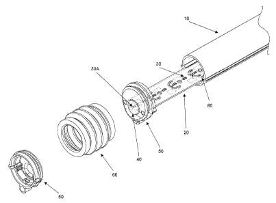
With reference to Figure 2, one embodiment of the present invention is
illustrated having
particular regard to the region located between adjacently ,positioned
elongated members.
This is an exploded view of the lighting apparatus in order that the
interconnection of the
components can be identified. A first elongated tubular member 10, has a
substrate 20
slidably connected thereto by a mounting means ~0, which in this instance are
in the form of
two flanges. Integrated onto the substrate are a plurality of light emitting
devices 30 for
providing illumination of the apparatus. Enclosing the end of the elongated
tubular member
is an end cap 50 having a protrusion 40 therein which projects towards the
region of
separation of the adjacent members. Positioned within the protrusion 40, is a
light emitting
device 30A which provides a means for illuminating the region of separation of
the adjacent
elongated tubular members. In Figure 2, a second elongated tubular member is
not shown,
however the end cap for sealing this member is illustrated. The opposite ends
of the
elongated tubular members can be sealed with similar endcaps or alternate end
caps
depending on the desired functionality at that particular end of the tubular
member.
Enclosing the separation region between the adjacent elongated tubular members
is a flexible
interconnector 60 which can provide a means for visually concealing the
separation region,
wherein this interconnector is sufficiently flexible such that it is capable
of lengthening or
shortening as the elongated members undergo thermal expansion or contraction.
Elongated Tubular Member°
CA 02434689 2003-07-09
Each elongated tubular member has at least one substrate slidably inserted
therein, wherein
this member provides a means for protecting the substrate and the associated
electronics from
the environment in addition to diffusing the light created by the light
emitting devices within
the elongated tubular member. Each elongated tubular member has at least one
open end
enabling the insertion of a substrate therein.
In one embodiment of the invention an elongated tubular member comprises an
internal
mounting system which enables the positioning of a substrate within the
elongated tubular
member. This mounting system provides a means for slidable connection between
the
elongated tubular member and the substrate thereby enabling differential
thermal expansion
of the substrate and the elongated tubular member to occur without one of
these elements
inducing stress within the other due to different coefficients of thermal
expansion. In one
embodiment of the invention, the mounting system can be fabricated in the form
of a double
flange fabricated on the internal surface of the elongated tubular member.
This double flange
can provide a groove in which a substrate can be slidably placed, wherein the
width of this
groove is sufficient to enable the slidablity of the substrate therein. In an
alternate
embodiment, a single flange can be provided, wherein the flange limits the
movement of a
substrate within the internal cross section of the elongated tubular member in
one direction.
In this embodiment the movement in the opposite direction can be limited by
the width of the
substrate itself, through contact with the interior of the elongated tubular
member.
Additionally, a groove formation can be fabricated within the wall thickness
of the elongated
tubular in order to provide the mounting system, however in this case the
thickness of the
wall of the elongated tubular member in the region of groove fabrication may
be greater than
other areas in order to provide sufficient material to create this groove.
Alternate forms of
mounting systems can be provided within the interior of an elongated tubular
member which
provide the desired functionality and these alternate forms would be readily
understood by a
worker skilled in the art.
The positioning of the mounting system within the cross section of the
elongated tubular
member and hence the position of the light emitting devices associated with a
substrate, can
be determined in order to provide a desired lighting effect. For example, in
the case where a
9
CA 02434689 2003-07-09
single face of an elongated tubular member is visible, by positioning the
illumination sources
(light emitting devices) at a position further removed from the face of light
emission, a
reduction in lighting hotspots can be provided, wherein hotspots can be
identified as more
brightly illuminated locations. In this manner a more uniform lighting
distribution may be
realised along the length of the elongated tubular member. The alternate
positioning of the
light emitting devices can produce more apparent lighting hotspots if this
effect is desired.
Alternately, if an elongated tubular member can be seen from both sides, the
central
positioning of the mounting system may be more desirable and incorporates a
substrate with
light emitting devices on both side thereof, for example.
In one embodiment of the invention, an elongated tubular member further
comprises an
external mounting feature, which provides a means for the securement of an
elongated
tubular member to a surface. This mounting feature can be provided in the form
of a ridge or
flange which is fabricated on the external surface of the elongated tubular
member and can
provide an attachment location for a connection device, wherein this
connection device is
fixedly connected to the surface. The connection device can be in the form of
a clip, clamp
or any other type of device which would be able to connect with the external
mounting
feature provided on the elongated tubular member. This external mounting
feature can be
provided along the entire length of the elongated tubular member thereby
enabling the
connection device to secure itself at any point along the length of the
member. Optionally,
the mounting feature can only be provided at predetermined positions along the
length of the
member.
In one embodiment of the invention, a single connection device is used to
secure a single
elongated tubular member to a surface. In this manner the thermal
expansion/contraction of
the elongated tubular member is not restricted by the connection device as it
would be if two
connection devices where used. In the case of two connection devices, the
expansion and
contraction of the length of the elongated tubular member between the
connection devices
may be limited, if no means for enabling differential movement of the
elongated tubular
member with respect to the connection device is provided. If one connection
device is used
to secure each elongated tubular member to the surface, this connection device
can be
CA 02434689 2003-07-09
positioned at the central length point of the elongated tubular member to
provide for
example, balance, ease of installation or uniformity of expansion/contraction
within the
region of separation of the elongated tubular members.
With reference to Figure 3, a perspective view of one embodiment of an
elongated tubular
member 10 is illustrated. The elongated tubular member comprises a mounting
system 80
provided on the internal surface of the member and a mounting feature 90 on
the exterior
thereof to provide for securement to a surface at the deployment site.
I O In one embodiment of the present invention, the elongated tubular member
can be fabricated
in a manner such that a curved member is produced. This type of feature can be
appropriate
if the surface of the deployment site is curved or if a particular design is
desired to be created
using the apparatus of the present invention. The range of the radius of
curvature of the
elongated tubular member can be between 1 m to 14m or may be greater,
depending on the
desired effect. In this case the one or more substrates to be inserted into an
elongated tubular
member of this configuration would be fabricated with a similar radius of
curvature thereby
enabling ease of their insertion therein. As would be readily understood, the
radius of
curvature of an elongated tubular member should be consistent over its length
in order to
enable the insertion of the one or more substrates within this member.
However, multiple
interconnected members having different radii of curvature can be
interconnected to produce
a desired effect.
In one embodiment of the invention, an elongated tubular member can be
fabricated in a
number of cross sectional shapes, wherein a particular shape may provide a
desired
illumination characteristic or architectural feature, for example. Potential
cross sectional
shapes of an elongated tubular member can be circular, rectangular, trapezoid,
octagonal or
any other shape desired or optionally the cross section shape of the elongated
member can
change over its length. However, if the cross section of the member changes
over its length,
the positioning of the mounting system within the interior of the elongated
tubular member
should be consistent in order to enable the insertion of one or more
substrates therein.
11
CA 02434689 2003-07-09
In one embodiment of the invention, an elongated tubular member can be
designed in a
manner that it is fabricated from a combination of multiple pieces. For
example., a rear
portion can be mounted on a surface at the deployment site and the front can
be removable or
interchangeable. This type of feature can enable the modification of the look
and
illumination characteristics of an elongated tubular member without the
complete
replacement of the entire section. These multiple pieces can clip or snap
together forming a
water tight seal along the length of the elongated tubular member.
The elongated tubular member can be manufactured from a plurality of
materials, however
I O the material selected must enable the passage of light therethrough.
Possible materials can
include plastic, polycarbonate, fibreglass or others as would be readily
understood. For
example, if fibres are integrated into the material, these elements may
provide an additional
visual feature for the elongated tubular member during its illumination. In
addition, the
material can be any colour, wherein the colour of the material can be used to
produce the
desired lighting effect, for example green or red light or may further enhance
the colour of
light being produced by the light emitting devices. Additionally the material
colour can
change along the length of the elongated tubular member. The material may also
have a
milky or opaque appearance when not illuminated, thereby being able to conceal
the internal
components during periods of non illumination.
In one embodiment of the invention, an elongated tubular member is fabricated
such that
additional diffusion, refraction or reflection characteristics can be
provided. The member can
be fabricated such that along its length or at desired or random locations, a
prismatic effect is
integrated into the member in the form of lenses or other light manipulating
devices. This
type of effect can be produced by for example varying the cross sectional
shape of the
elongated tubular member, varying the thickness of the walls, insertion of
elements having
the desired characteristics or other means as would be readily understood. In
addition,
reflectors and refractors can be integrated into the member enabling the
redirection of the
light being produced by the light emitting devices. In this manner, light
which would not
have been visible due to its direction of projection, can be redirected such
that it is visible,
thereby potentially improving the desired lighting capability of the
apparatus. For example, if
12
CA 02434689 2003-07-09
the lighting system is illuminating a canopy and a person will typically be
viewing this
canopy from a position which is horizontal thereto or below, the angle of
projection of the
created illumination may be desired to be to be within the 90 degree region,
for example from
directly below to horizontally in front of the illumination system. In this
example, reflectors
can be integrated onto the internal surface such that light is projected in
this direction only.
The fabrication of an elongated tubular member can be provided by a number of
methods
including extrusion, injection moulding or other methods as would be readily
understood by a
worker skilled in the art. For example, if the member is extruded, the cross
section thereof
I O will typically be uniform over the entire length and may provide ease for
length adjustment at
the installation site since all features associated with the elongated tubular
member are
provided along the entire length.
Lighting Components
The lighting components associated with the elongated lighting apparatus
comprise a
plurality of light emitting devices that are associated with a substrate which
is inserted into an
elongated tubular member, wherein these lighting components provide the
illumination. The
light emitting devices are electrically interconnected to a power source which
provide a
means for their activation. There may be a single power source for the entire
lighting
apparatus or a number of power sources wherein a power source is used to
energise a
predetermined number of light emitting devices or for example all of the light
emitting
devices within one, two or three elongated tubular members. In the event where
a power
source is used for the activation of the light emitting devices in multiple
elongated tubular
members, these members are electrically interconnected in a manner that can
maintain the
sealed nature of the elongated tubular member.
At least one light emitting device is positioned on a substrate in a manner
that enables its
positioning proximate to the protrusion provided in an end cap that is
sealingly connected to
an open end of an elongated tubular member. This light emitting device
provides a means for
the illumination of the separation distance between adjacent elongated tubular
members. As
such this at least one light emitting device must be positioned at the end of
the substrate
13
CA 02434689 2003-07-09
proximate to the end cap. In one embodiment of the invention and as
illustrated in Figure 4,
a substrate is designed such that the end thereof is capable of insertion into
the protrusion that
is integrated into an end cap. In this manner a light emitting device 30A can
be positioned
within the protrusion thereby potentially enhancing the illumination of the
separation region.
The shape of the end of the substrate can be determined by the size and shape
of the
protrusion in the end cap or optionally, a standard end of the substrate can
be designed such
that it is compatible with a plurality of shapes of protrusions.
In one embodiment of the invention, a substrate can be designed in a manner
such that its
length can be modified such that this modification of the length does not
affect the
functionality thereof. As illustrated in Figure 4, modification locations 100
can be predefined
on a substrate wherein upon the modification of the substrate and appropriate
shape of the
new end of the substrate is realised. In addition, the modification locations
100 provided on a
substrate can be spaced uniformly along the length of a substrate or can
optionally be
positioned at varying locations along the length of the substrate. For
example, one end of a
substrate may have modification locations spaced at one inch intervals and the
opposite end
of the substrate may have modification locations spaced at two inch intervals.
The spacing of
the light emitting devices may be determined based on the modification
locations on the
substrate and therefore there may be denser clusters of light emitting devices
at certain
regions of a substrate, and the control of the intensity of the illumination
produced by the
light emitting devices can enable a uniform intensity of light being produced.
Due to the
ability to modify the length of a substrate, a standard substrate can be
manufactured thereby
resulting in a potential cost savings associated with the manufacturing
process due to the
standardised production of substrates.
In one embodiment of the invention, the light emitting devices can be arranged
in a linear one
dimensional array or a planar two dimensional array. A two dimensional array
can provide a
means for the integration of more light emitting devices onto a substrate and
therefore an
increase in the illumination provided thereby. In addition, the light emitting
devices can be
designed in order to produce a desired visible wavelength of light thereby
producing the
desired illumination colour. Optionally, the design of the light emitting
device can be such
14
CA 02434689 2003-07-09
that the desired illumination colour is a combination of the wavelength
produced by the light
emitting device and its interaction with the type and/or calaur of the
material used to form the
elongated tubular member. Additionally, in arder to produce a desired effect,
varying light
emitting devices and hence colour illumination produced thereby can change
along the length
of the substrate.
In one embodiment, wherein the light emitting devices are arranged in a two
dimensional
array, there can be a collection of light emitting devices in a direction
perpendicular to the
longitudinal axis of the substrate. For example, these light emitting devices
can produce red,
green and blue light respectively, wherein using specific control parameters
for each of these
three colours light emitting devices can enable the production of any visible
colour. In this
manner a particular elongated lighting apparatus is capable of producing any
visible colour in
the spectrum in addition to adjusting this colour during operation.
In one embodiment of the invention controllers are integrated into the
elongated lighting
apparatus which provide a means for controlling the activation and the
illumination level
produced by the light emitting devices. In this manner the various light
effects can be
produced by the elongated lighting apparatus, for example the simulation of
movement of the
illumination along the length of the apparatus. In addition, the control of
the light emitting
devices can be used in order to control the illumination level produced
thereby. In the case
where a uniform lighting level is desired along the length of the lighting
apparatus either the
density of the placement of the light emitting devices should be uniform or
alternately in
areas of a higher density of light emitting devices these elements should be
controlled in a
manner that can reduce the illumination intensity produced by each light
emitting device such
that the summation thereof is uniform with other locations on the substrate.
For example, a
resistor can alter the current being supplied to a light emitting device and
thus adjust the
illumination level produced thereby, alternately the controller can be in the
form of a
microprocessor. A worker skilled in the art would readily understand the type
of controllers
which would be required in order to provide a desired effect.
15
CA 02434689 2003-07-09
In one embodiment of the invention, the substrate is in the form of a printed
circuit board
wherein the electrical interconnection and the controllers of the light
emitting devices is
integrated thereon. This type of configuration can produce a simplified manner
is which to
fabricate the elongated lighting apparatus on site, for example.
In one embodiment of the invention, one or more reflectors can be integrated
on a substrate,
wherein these reflectors provide a means for redirecting the light produced by
the light
emitting devices to a more desirable location. These reflectors can be
designed in a linear
configuration wherein they are provided along the length of a substrate or
optionally a
particular reflector can be associated with a particular light emitting
device. The shapes and
design of a reflector is dependent on the desired redirection of the light
being produced by
one or more light emitting devices as would be readily understood by a worker
skilled in the
art.
End Cap
The open ends of the elongated tubular members are enclosed by end caps that
enable the
sealing of these members. At least one of the end caps proximate to a region
of separation,
has a protrusion therein that projects towards the region of separation and
this protrusion is
fabricated from a material that allows the passage of light therethrough. The
protrusion
within the end cap provides a means for directing and distributing light
generated by a light
emitting device proximate thereto, into the separation region resulting in the
illumination of
this region. One embodiment of an end cap according to 'the present invention
is illustrated
in multiple views in Figures SA, SB and SC.
While illuminating the separation region from only one side thereof can be
sufficient, by
providing end caps with projections therein and the proximate light emitting
devices, on both
ends of the elongated tubular members which are adjacent to the region of
separation, a more
even and uniform distribution of light within the region of separation can be
provided.
The location of the protrusion that is fabricated in an end cap can be
determined based on the
positioning of the substrate within the elongated tubular member thereby
enabling the
16
CA 02434689 2003-07-09
alignment of a light emitting device within the protrusion. As sLich the
protrusion can be
aligned with the centre Line of the end cap or alternately it can be
positioned such that it is
above or below the centre point of the end cap.
The shape of the protrusion can be designed in a manner such that a desired
optical
performance is provided, thereby illuminating the separation region in a
desired manner. For
example, a partial spherical shaped protrusion can enable relatively even
light dispersion
within the separation region, while a protrusion with a number of planar
sides, for example a
partial cube or octahedron can result in a more segmented illumination of the
separation
region. In one embodiment of the invention, additional optics can be
integrated into a
protrusion which can enable light focusing, separation, reflection or
directing of the light
along a desired path. These types of optics can include refractive elements,
prisms, reflectors
and other optical components which would provide the desired effect and would
be readily
understood by a worker skilled in the art.
IS
The end cap is used to seal the open ends of the elongated tubular members and
this end cap
can form this seal with either the interior or exterior surface of the member.
This seal can be
formed through the use of glue, sealing rings or a pressure type fgt between
the end cap and
the member or other means. With reference to Figure SA and 51~, in one
embodiment of the
invention the interconnection surface 145, is designed to be placed on the
exterior of the
elongated tubular member and the end cap includes nodules 115 which also
enclose the
mounting feature associated with elongated tubular member. In one embodiment
the end cap
further comprises an attachment feature which provides for its interconnection
with a flexible
interconneetor. It should be noted that this attachment feature does not have
to provide a seal
since the flexible interconnector only encloses a separation region between
the elongated
tubular members. As illustrated in Figure SC the attachment feature 140 can be
in the form
of a groove wherein a lip fabricated on the flexible interconnector can be
inserted into this
lip.
In one embodiment of the invention and with further reference to Figure SA,
there are
provided an entrance aperture 120, an exit aperture 130 and a conduit
therebetween in order
17
CA 02434689 2003-07-09
to enable wire or cable to exit an elongated tubular member while still
maintaining the
sealing quality of the end cap. This feature can provide a means for a power
supply to be
electrically connected to the substrate ~~ithin an elongated tubular member in
addition to
enabling the electrical interconnection of substrates in adjacent elongated
tubular members.
In order to maintain the sealing quality of the end cap which incorporates
these apertures, the
aperture can be positioned at the bottom of an end cap and thereby limit the
movement of
moisture into the elongated tubular member or optionally upon the insertion of
the wire or
cable within the apertures a sealing substance, for example caulking, can be
used to provide
additional sealing qualities.
In one embodiment, an end cap is fabricated with a substrate retaining system
which provides
a means for maintaining the position of the substrate within the end cap and
thus
predetermining the position of the light emitting device proximate to the
protrusion. This
feature, as with the elongated tube can be fabricated in the form of a double
or single flange
or alternately can be fabricated in the form of a groove. Figure SA
illustrates the substrate
retaining system 110 as a double flange type configuration.
In one embodiment of the invention, the end cap can have fabricated within its
interior a clip
type feature which can be used to interconnect the end cap with the substrate
which is
inserted within the elongated tubular member, thereby maintaining the position
of the
substrate during differential expansion/contraction of the apparatus. In this
manner the
proximity of a light emitting device to a protrusion within the end cap can be
maintained.
This type of mechanical connector between the substrate and end cap would
typically be
provided at one end of a elongated tube if there is a single substrate
therein, or both ends if
there are at least two substrates. If there are two substrates the electrical
interconnection
therebetween can be provided by simple wires that are of sufficient in length
to account for
maximum differential movement between the elongated tubular member and the
substrates.
The end cap can be manufactured from a plurality of materials, however the
material selected
must enable the passage of light therethrough. Possible materials can include
plastic,
polycarbonate, fibreglass or others as would be readily understood. In
addition, the material
18
CA 02434689 2003-07-09
can be any colour, wherein the colour of the material can be used to produce
the desired
lighting effect, for example green or red light or may further enhance the
colour of light being
produced by the light emitting devices. As the end cap is typically concealed
by a flexible
interconnector, an end cap can be formed from a transparent material. In one
embodiment
wherein the end cap is fabricated from a transparent material, the external
faces of the end
cap, excluding the surfaces concealed by a flexible interconnector, for
example the
protrusion, are fabricated with a textured finish in order to diffuse light in
a plurality of
directions, which can result in a more distributed illumination and more even
illumination
along the entire length of the elongated lighting apparatus.
Flexible I~ate~conneeto~
A flexible interconnector encloses the separation region between two adjacent
elongated
tubular members thereby enabling the concealment of this region. This
connector is designed
to undergo deformations upon the expansion/contraction of the elongated
tubular members to
which it is connected, while maintaining the enclosure of the separation
region. A flexible
interconnector is fabricated from a material that enables the passage of light
therethrough
thereby enabling the visual illumination of this region. As with the elongated
tubular
member, the flexible interconnector can be fabricated from a coloured material
thereby
resulting in the adjustment of the visible wavelength that is produced by the
light emitting
device proximate to the protrusion in an end cap.
In one embodiment of the invention, the flexible interconnector is fabricated
from a highly
flexible and elastic material wherein this material linearly encloses the
separation region.
Alternately the flexible interconnector is designed having a bellow type
configuration as
illustrated in Figure 6 and fabricated from a flexible material. The bellow
type structure of
the flexible interconnector can provide additional structural strength in the
direction
perpendicular to the accounted expansion/contraction of the elongated tubular
members and
thereby may be more resistant to movement in this direction due to snow
loading, wind or
rain, for example.
19
CA 02434689 2003-07-09
In an alternate embodiment of the invention, the flexible interconnector can
be fabricated as a
telescopic device wherein stiff or rigid members slide inside on another in
order to account
for the expansion/contraction of the elongated tubular members.
The flexible interconnector can be interconnected with either an end cap or
the elongated
tubular member directly depending on the design of the components. In one
embodiment, the
flexible interconnector comprises a lip at its end which interconnects with an
end cap by way
of a groove 140 formed therein as illustrated in Figure SC. Through the
interconnection of
the flexible interconnector with the end cap, modification of the length of an
elongated
tubular member would not affect the securement of the flexible interconnector
as would
happen if a groove for the interconnection was formed within the elongated
tubular member.
Biasing System
In one embodiment, wherein two or more substrates are enclosed within a single
elongated
tubular member a biasing system is used to interconnect these substrates,
wherein this biasing
system provides a means for electrical interconnection of the substrates in
addition to
supplying a resistive force in order to provide a means for maintaining the
position of the one
or more light emitting devices within the protrusion in an end cap. In this
manner the biasing
system enables differential expansion/contraction of the substrate with
respect to the
elongated tubular member while maintaining a desired position of the
substrates within the
member.
The biasing system comprises two conductive elements and a resistive element.
The
conductive elements provide electrical interconnection between the substrates
and is capable
of accommodating differential movement between the substrates while
maintaining an
electrical connection and not stressing connection points between the
substrates and the
conductive element. As would be readily understood one conductive element
provides
positive charge connection and the other provides negative charge connection
between the
substrates. The resistive element provides a restorative force for maintaining
the position of
the substrates at the ends of the elongated tubular member.
CA 02434689 2003-07-09
Figure 7 illustrates a biasing system according to one embodiment of the
invention and
Figure 8 illustrates an exploded view thereof. The conductive elements 160
have a spring
like element 165 in a middle region which provides for the elongation or
contraction of the
conductive element. With regard to Figure 8, the stud 190 on the resistive
element inserts
into an opening 195 in the conductive element thereby ensuring that the
connection point 180
in this vicinity does not move under differential thermal
expansion/contraction. This type of
feature is provided for the two connection points associated with each
conductive element.
As an alternate possibility, the conductive element can be a simple wire
connection which has
sufficient slack in order to enable the maximum potential space between the
connection
points on adjacent substrates to be realised.
The resistive element is designed such that the deformation thereof is
confined to a
predetermined region and as such the remainder of the resistive element
essentially does not
deform due to differential thermal expansion/contraction. In this manner the
portion of the
resistive element which interconnects with a substrate does not introduce a
level of
undesirable stress into the substrate to which it is connected. The region of
deformation
within the resistive element is designed such that at a temperature wherein
the greatest
separation distance between the substrates within an elongated tubular member
is realised,
the resistive element is still minimally compressed thereby still forcing the
substrates to the
extremities of the elongated tubular member.
One embodiment of the resistive element is illustrated in an exploded view in
Figure 8. In
this embodiment, the resistive element is formed by the interconnection of two
like elements.
Each portion of the resistive element comprises two nodules 200 and 210 which
interconnect
with mating holes within a substrate as illustrated in Figure 4. By the
interconnection of the
resistive element to a single substrate via two points, rotation between the
resistive element
and the substrate is limited thereby reducing the possibility of the
substrates binding within
the mounting means associated within the elongated tubular member. Figures 9
and 10
illustrate a biasing system interconnected to two substrates according to one
embodiment of
the invention.
21
CA 02434689 2003-07-09
The resistive component can be fabricated from a pluralit~~ of materials for
example resilient
plastic, polycarbonate or other polymer or other material. However the
selection of the
material must be capable of deformation and provide a restorative force in a
wide range
temperatures. Material typically becomes more brittle in cold temperatures
therefore the
selection of the appropriate material can be based on this type of factor for
example. A
worker skilled in the art would readily understand what other types of
materials would be
appropriate for the fabrication of the resistive component.
It would be readily understood that the various materials that are selected
for the fabrication
of all of the components of the elongated lighting apparatus according to the
present
invention, are capable of maintaining their integrity in a wide range of
temperatures, ranging
from -60°C to 60°C, for example.
The embodiments of the invention being thus described, it will be obvious that
the same may
I S be varied in many ways. Such variations are not to be regarded as a
departure from the spirit
and scope of the invention, and all such modifications as would be obvious to
one skilled in
the art are intended to be included within the scope of the following claims.
22