Note: Descriptions are shown in the official language in which they were submitted.
CA 02434752 2003-07-07
[600.1237; A3779]
COMPACT DEVICE FOR IMAGING A PRINTING FORM
[0001] The present invention relates to a device for imaging a printing form,
including a
number of light sources as well as imaging optics for producing a number of
image spots of
the light sources on the printing form, the imaging optics including at least
one macro-optical
system of refractive optical components.
[0002] In order to pattern printing forms, in particular printing plates, into
ink-accepting and
ink-repelling regions, the printing form surface, which is initially in an
unpatterned, for
example, ink-accepting state, is often partially exposed to the influence of
electromagnetic
radiation, in particular heat or light of different wavelengths, so as to
produce the other, for
example, ink-repelling state at the affected positions. To image a printing
form selectively,
accurately and rapidly, a number of individually addressable light sources, in
particular laser
light sources, that are arranged in an array in rows or in the form of a
matrix are often used in
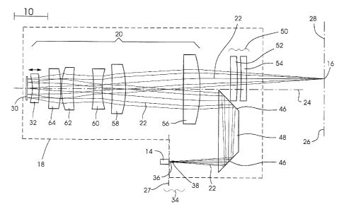
parallel operation, the light sources being projected through imaging optics
onto the surface of
the printing form, which is located in the image field of the imaging optics.
[0003] In this context, a number of requirements for the fulfillment of
various functionalities
are placed on an imaging optical system in such a device for imaging a
printing form, whether in
a printing form imaging unit or in a printing unit. First of all, a part of
the imaging optics is
intended for globally projecting the number of light sources to image spots
with as few
imaging defects as possible. In the context of description, this part is
referred to as "macro-
optics". Secondly, further parts of the imaging optics or parts of the macro-
optics itself can
fulfill additional functionalities, such as a possibility of adjusting the
focus position.
[0004] Frequently, the light source arrays are composed of a, certain number
of individually
addressable diode lasers, preferably single-mode diode lasers, which are
arranged on a
semiconductor substrate at certain intervals, typically at substantially equal
intervals, and
which have a common output plane that is precisely defined by the crystal
fracture plane
(IAB, individually addressable bar). Since the light-emission cones of these
diode lasers have
different opening widths in the two essentially orthogonal planes of symmetry,
there is a need
for optical correction to reduce the asymmetric divergence of the emerging
light. The ratio of
opening angles can be adjusted individually. This correction is carried out
with respect to the
individual light sources using a part of the imaging optics that is also
referred to as "micro-
CA 02434752 2003-07-07
600.1237
optics".
[0005] A number of imaging optics which were designed especially for
projecting diode
laser rows in order to image an image carrier are known from the prior art.
For example, U.S.
Patent No. 4,428,647 describes an imaging device including a semiconductor
laser array whose
individual lasers each have associated therewith a nearby lens for correcting
divergence. The
light of the semiconductor lasers is then collected by an objective lens and
focused onto an
image carrier. An imaging device having an individually addressable diode
laser array is
known from European Patent Application No. EP 0 878 773 A2. The imaging optics
has a
micro-optical part and a macro-optical parts. The macro-optical part is a
confocal lens
arrangement that is telecentric on both sides. Prior German Patent Application
No. DE 101
15 875.0 describes an imaging device having an array of light sources. The
imaging optics
includes micro-optics which produces virtual intermediate images of the light
sources as well
as macro-optics which contains a convex mirror and a concave mirror having a
common
center of curvature, a combination of the so-called "open type" and which
produces a real
image of the virtual intermediate images.
[0006] The approaches known from the prior art have in common that they
require a large
installation space compared to their functionalities. Modification or
complementation with
further functionalities can only be achieved with difficulty. Since, first of
all, the
installation space in such machines is very limited and, secondly, the design
or configuration
of the printing form imaging unit or of the printing unit can be modified only
slightly for
implementing an imaging device, it is necessary to reduce the installation
space requirement
without limiting the necessary functionalities. Moreover, an imaging optical
system on a
printing press or on a printing form imaging unit is subject to shocks or
vibrations, which is
why optical systems known from the prior art can generally not easily be
transferred for use
on a printing form imaging unit or inside a printing unit of a printing press.
[0007] The object of the present invention is to provide a compact device for
imaging a
printing form which allows easy integration into the available installation
space in a printing
unit of a printing press.
[0008] This objective is achieved according to the present invention by a
device for
imaging a printing form having the features recited in Claim 1. Advantageous
refinements
2
CA 02434752 2003-07-07
600.1237
of the present invention are characterized in the dependent claims.
[0009] According to the present invention, a device for imaging a printing
form has a
number of light sources as well as imaging optics for producing a number of
image spots of
the light sources on the printing form. The imaging optics includes at least
one macro-optical
system of refractive optical components or optical elements, in particular, a
number of lenses,
which is traversed twice by the optical path from the light sources to the
image spots. In the
context of this description, the word "optical path" is understood to mean all
the optical paths
of the number of light sources. In particular, the refractive optical
components are passed
through twice. It is the refractive optical components that substantially
contribute to the
generation of the number of image spots. Since the optical path passes through
the macro-
optics multiple times or repeatedly, the macro-optics can have a more compact
and
installation-space saving design compared to macro-optics having a simple
optical path, while
maintaining the same functionality. The number of light sources can also be 1;
preferably,
however, provision is made for a plurality of light sources. The light sources
can be
arranged in a one-dimensional array (line, preferred) or in a two-dimensional
array, in
particular in a regular array, preferably in a Cartesian arrangement. The
light sources
and the image spots are in a one-to-one functional relationship with each
other. The image
spots are disjunct from each other. It is possible for the image spots to be
dense or,
preferably, not to be dense with respect to each other; that is, their spacing
can be greater than
the minimum spacing of the printing dots to be placed. The spacing of
neighboring image
spots on the printing form in units of the minimum printing dot spacing is
preferably a natural
number that is relatively prime to the number of image spots (light sources).
The printing
form is preferably an offset printing form.
[0010] In this context, the optical path can run non-centrally through the
macro-optics. In
particular, the optical path can be different on the first path through the
macro-optics than on
the second path through the macro-optics. Moreover, the optical path can run
symmetrically
to the optical axis of the macro-optics. In particular, the first path can run
symmetrically to
the second path.
[0011] The double passage of the optical path through the macro-optics can be
such that the
first principal plane and the second principal plane of the macro-optics are
located on one side
of the macro-optics. The macro-optics can be designed in such a manner that
objects (a
3
CA 02434752 2003-07-07
600.1237
number of light sources) and images are located on one side of the macro-
optics. In other
words, the optical path passes through the macro-optics on a first path in a
first direction and
on the second path in a direction opposite to the first direction.
[0012] In an advantageous embodiment of the device for imaging a printing
form, at least
one mirror, in particular a plane mirror, is associated with the macro-optics.
The macro-
optics can be designed in such a manner that the optical path passes through
the macro-optics
in a first direction on its first path until the light hits the at least one
mirror, whereupon it
passes through the macro-optics in a direction opposite to the first direction
on its second
path. The macro-optics is virtually equal to an optical system of double the
size. In other
words, a macro-optical system composed of a number of optical elements is
optically doubled
in size or doubled by the mirror or mirrors; the mirror or mirrors reflecting
the light into a
symmetrical second passage through the macro-optics.
[0013] In a device according to the present invention for imaging a printing
form, the
macro-optics can include at least one part that is designed as an adaptive
optic, or at least one
of the associated mirrors can be designed to be adaptive. In particular, at
least one of the
associated mirrors can be designed as an adaptive mirror, i.e., with a
variable radius of
curvature or with a variable surface structure. By varying the radius of
curvature, it is possible
to change the image width. A variation of the radius of curvature is small
compared to the
dimensions of the adaptive mirror. The adaptive mirror can also enable the
wavefront of the
light to be manipulated on the optical path through the macro--optics, for
example, to achieve
an axial change in focusing/defocusing. The adaptive mirror can be an
adjustable element for
compensating imaging defects. An adaptive mirror can be a membrane mirror, an
electrostatic mirror, a bimorph mirror, a piezoelectrically driven (for
example, polish-milled)
metal mirror, or the like.
[0014] In an advantageous embodiment of the device according to the present
invention for
imaging a printing form, the macro-optics can include at least one movable
lens, or,
alternatively, a movable mirror. The movable lens is preferred, in particular
because the
telecentricity of macro-optics is maintained although the lens is moved. When
the printing
form or printing plate is clamped to a cylinder, the attachment often causes a
disturbing
curvature ("plate bubble"), which can be on the order of several 100
micrometers. Due to the
curvature, it is possible for the printing form surface to come to rest
outside the usable focal
4
CA 02434752 2003-07-07
600.1237
range of the laser radiation so that the power density of the laser radiation
at such a distance
from the focus position is not sufficient to achieve an acceptable imaging
result. A movable
lens in the macro-optic makes it possible for the focus position of the laser
radiation to be
moved (refocused) in the direction of the optical axis in a simple manner. The
accuracy
requirements for this refocusing result from the depth of focus of the laser
beams. The device
according to the present invention allows easy integration of the
functionality of focus
displacement. The device has a defined distance between the last optical
component and the
printing form, the distance remaining unchanged by the focus displacement. At
the same
time, it is possible to obtain a good ratio between the displacement of the
movable lens and
the focus position variation.
[0015] In an advantageous embodiment of the device for imaging a printing
form, the light
sources are individually addressable lasers. Each light source corresponds to
an individually
addressable imaging channel having one imaging beam. In particular, the light
sources can
emit in the infrared (preferred), visible, or ultraviolet spectral ranges. In
an advantageous
refinement, the lasers can be tunable and/or operated in pulsed mode in the
nanosecond,
picosecond, or femtosecond regime. The individually addressable lasers can be,
in particular,
diode lasers or solid lasers. The individually addressable lasers can be
integrated on one or
more bars, which, in particular, can be one or more individually addressable
bars (LAB),
preferably single-mode. A typical IAB includes 4 to 1,000 lasers, in
particular, 30 to 260 lasers.
The lasers are located on the IAB preferably at substantially equal intervals,
in particular in a
line (one-dimensional array) or on a grid (two-dimensional array).
[0016] In the device according to the present invention for imaging a printing
form, a micro-
optical system can be arranged downstream of the number of light sources along
the optical
path, the micro-optics being arranged upstream of the macro-optics along the
optical path.
For diode lasers, in particular on a bar, the micro-optics can be used, inter
alia, for adjusting
the beam diameters. Due to the very small diameters of the individual laser
beams at the front
of the LAB, typically a few micrometers in the horizontal direction (slow
axis) and a few
micrometers in the vertical direction (fast axis), the beam diameters need to
be adjusted in
both axes independently of each other in order to achieve the diameters needed
on the printing
form, typically a few micrometers in the horizontal or vertical directions.
The aim is to obtain
fundamental mode Gaussian laser beams that are as ideal as possible, because
these have the
greatest natural depth of focus and, thus, are maximally insensitive to shifts
in focus or "plate
CA 02434752 2003-07-07
600.1237
bubbles". The lasers are preferably operated in single mode. A micro-optics
can be arranged
downstream of the individually addressable lasers, allowing the beam diameters
of the light
beams emerging from the lasers to be influenced in two orthogonal axes
independently of
each other, i.e. to be adjusted independently of each other. The image spots
of the micro-
optics (intermediate image) can be real or virtual. In particular, the micro-
optics can be
produce a virtual, enlarged intermediate image of the number of light sources
that is projected
by the macro-optics.
[0017] In the device according to the present invention for imaging a printing
form, it is
particularly advantageous if the light of the number of light sources is
coupled into the macro-
optics via at least one light-deflecting element. This measure makes it
possible to make the
design even more compact. As an alternative to a mirror pair, it is possible
and preferred to
use a Porro prism as the light-deflecting element to couple the light of the
number of light
sources into the macro-optics. Using a Porro prism, it is also possible to
adjust the optical
path through the macro-optics.
[0018] In an advantageous embodiment, the macro-optics of the device according
to the
present invention is telecentric on both sides. In this connection, it should
be pointed out that
during focusing, for example, using an adaptive mirror or a movable lens in
the macro-optics
of the device according to the present invention, the telecentricity is
maintained. In other
words, the object-to-image distance is changed by the focus displacement
described in detail
above, while the object distance is fixed. Using an optical path that is
telecentric over the
whole extent, it is achieved that the size of the image is not changed or
changed only within
very small tolerances of typically 1 micrometers in the directions orthogonal
to the beam
propagation (optical axis). Moreover, the macro-optics can advantageously be
designed to
allow imaging essentially without changing the size, especially preferably 1:1
imaging. The
focal length of the macro-optics is preferably infinite.
[0019] In an advantageous embodiment of the device according to the present
invention,
correction optics for adjusting the image size can be arranged downstream of
the macro-optics
along the optical path. The correction optics permits very high positional
accuracy of the
image spots and preferably also a very accurate adjustment of the image size.
Preferably, the
correction optics is a zoom lens system of two lenses. The zoom lens system
itself is
telecentric on both sides, just as the macro-optics. The telecentricity is
maintained during
6
CA 02434752 2003-07-07
600.1237
adjustment of the image size.
[0020] In an advantageous embodiment of the device according to the present
invention,
neighboring image spots of the number of image spots of the light sources on
the printing
form can have a substantially equal distance a which is a whole-number
multiple of minimum
printing dot spacing p. In particular, the number of light sources can
advantageously be n,
with n being relatively prime to the number (a/p), so that a non-redundant
interleaving method
can be carried out for imaging the printing form. Obviously, n and (a/p) are
not both 1
simultaneously.
[0021] In a preferred embodiment of the device according to the present
invention for
imaging a printing form, the printing form to be imaged can be mounted on a
rotatable
cylinder. Alternatively, the surface of a rotatable cylinder can constitute a
printing form. In
other words, the printing form can be a plate-shaped printing form (having one
edge) or a
sleeve-shaped printing form (having two edges). It can be a (conventional)
printing form that
can be written once, a recoatable or a rewritable printing form. In the
context of this
description of the device according to the present invention, "printing form"
is understood to
include also a so-called "digital printing form". A digital printing form is a
surface that is
used as an intermediate carrier for printing ink before this printing ink is
transferred to a
printing substrate. In this context, the surface itself can be patterned into
ink-accepting and
ink-repelling regions, or only be provided with printing ink in a patterned
manner through
imaging. Interaction with laser radiation allows the digital printing form to
be patterned into
regions which do or do not deliver the printing ink to a printing substrate or
to an intermediate
carrier. The patterning of the digital printing form can be carried out prior
or subsequent to
applying ink to the printing form. The printing form can also be essentially
composed of the
printing ink itself, for example, for use in a thermal transfer method.
[0022] The imaging device according to the present invention can be used
especially
advantageously in a printing form imaging unit or in a printing unit of a
printing press. A
printing unit can contain one or more imaging devices. A plurality of devices
can be arranged
in such a manner that they can concurrently image partial areas of a printing
form. A printing
press according to the present invention, which features one or more inventive
printing units
can be a web-fed or sheet-fed press. A sheet-fed press can typically include a
feeder, a
delivery, and one or more finishing stations, such as a varnishing unit or a
dryer. A web-fed
7
CA 02434752 2003-07-07
600.1237
printing press can have a folding apparatus arranged downstream. The
underlying printing
method of the inventive printing unit or of the inventive printing press can
be a direct or
indirect planographic printing method, a flexographic printing method, an
offset printing
method, a digital printing method, or the like.
[0023] Also related to the inventive idea is a method for changing the
relative position of an
image spot with respect to the position of a printing form in a device for
imaging a printing
form, including a number of light sources as well as imaging optics for
producing a number of
image spots of the light sources on the printing form, the imaging optics
including at least one
macro-optical system. The method according to the present invention has the
feature that a
lens of the macro-optics that is traversed twice by the optical path is moved.
When using
macro-optics which is traversed twice by the optical path, the object-to-image
distance can be
changed by moving a lens in the macro-optics, while the object distance is
fixed.
Advantageously, the telecentricity is maintained. The method according to the
present
invention can preferably be carried out using a device for imaging a printing
form, such as is
described in this specification.
[0024] Further advantages as well as expedient embodiments and refinements of
the present
invention will be depicted by way of the following Figures and the
descriptions thereof.
Specifically,
Figure 1 shows a preferred embodiment of the imaging optics of the device
according to
the present invention for imaging a printing form;
Figure 2 shows a preferred embodiment of the micro-optics of the device
according to the
present invention for imaging a printing form, with Subfigure A in the
vertical
plane and Subfigure B in the horizontal plane;
Figure 3 is a schematic representation of an advantageous embodiment of the
device
according to the present invention for imaging a printing form on a printing
form
cylinder; and
Figure 4 is a schematic representation of an advantageous embodiment of the
device
according to the present invention for imaging a printing form in a printing
unit of
8
CA 02434752 2003-07-07
600.1237
a printing press.
[0025] Figure 1 shows a preferred embodiment of the imaging optics of the
device
according to the present invention for imaging a printing form. Along optical
path 22,
starting at the number of light sources 14, in a preferred embodiment an
individually
addressable diode laser bar (IAB), imaging optics 18 includes micro-optics 34,
a Porro prism
48, macro-optics 20, i.e. a lens system producing a 1:1 image, and correction
optics 50.
Imaging optics 18 produces a number of image spots 16 of the number of light
sources 14. At
the top left of Figure 1, a scale in millimeters is added for quantitative
purposes.
[0026] Using micro-optics 34, the beam diameters can be influenced
independently of each
other in the two orthogonal directions perpendicular to the propagation
direction (optical
axis). The micro-optics makes it possible to adjust the size of the spots to
be imaged. Figure
2 serves to illustrate in more detail micro-optics 34, which includes a fast-
axis lens 36 and a
slow-axis lens 38. The number of light sources 14 and micro-optics 34 can also
be enclosed
in a common housing. Porro prism 48, or alternatively two mirrors, is used to
couple the light
into the multiple-lens 1:1 lens system of macro-optics 20 and to align the
beams in the image
plane. Inner surfaces of Porro prism 48 serve as light-deflecting elements 46
through total
reflection. Macro-optics 20 includes a first lens 56, a second lens 58, a
third lens 60, a fourth
lens 62, a fifth lens 64, a movable lens 32 (the moving direction is indicated
by the double
arrow), and a mirror 30. The lenses of the macro-optics and mirror 30 are
arranged
axisymmetrically around the optical axis 24. Optical axis 22 does not run
along optical axis
24, but non-centrally or off-axis. Using mirror 30, which is preferably
provided with a highly
reflective coating, the light is reflected and passes through micro-optics 20
again; however, in
such a manner that it is symmetrically mirrored on optical axis 24 with
respect to the first
path. In other words, optical path 22 runs through macro-optics 20 such that
it is folded. First
principal plane 26 and second principal plane 28 of the macro-optics are
located on one side
of macro-optics 20, in particular, symmetrically. In the preferred embodiment
shown in
Figure 1, a Porro prism 48 is arranged upstream of macro-optics 20. In
consequence, spots of
mirrored principal plane 27, in which are located light sources 14, are imaged
onto second
principal plane 28 of macro-optics 20. To adjust the focus position of image
spots 16, the
object-to-image distance of macro-optics 20, which is traversed twice by the
optical path, is
changed in a controlled manner. In this embodiment, this is done by moving
movable lens 32.
Due to the double passage and the suitable design of macro-optics 20, a good
ratio between
9
CA 02434752 2003-07-07
600.1237
the displacement of movable lens 32 and the change in the focus position of
image spots 16 is
achieved; a displacement by s results in a change by m*s, with m >> 1. The
optical path
through macro-optics 20 is telecentric. In the embodiment shown in Figure 1,
telecentric
correction optics 50 including a first lens 52 and a second lens 54 is
arranged downstream of
macro-optics 20 for fine correction. Correction optics 50 is a two-lens zoom
lens system
which allows stepless adjustment of the image size in a range of plus or minus
a few percent,
approximately from 0.9 to 1.1.
[0027] Figure 2 shows a preferred embodiment of the micro-optics of the device
according
to the present invention for imaging a printing form. Subfigure A shows a view
in the vertical
plane in vertical direction 42 and with horizontal direction 40 out of the
plane of paper, while
Subfigure B shows a view in the horizontal plane in horizontal direction 40
and with vertical
direction 42 into the plane of paper. At the top left of Figures 2A and 2B, a
scale in
millimeters is added for quantitative purposes. In a preferred embodiment,
micro-optics 34 is
composed of a fast-axis lens 36 and a slow-axis lens 38. Fast-axis lens 36 is
a glass fiber
which is polished on one side and reduces the divergence of all beams of the
number of light
sources 14 in the fast axis thereof. Slow-axis lens 38 is an array of a.
number of cylindrical
lenses whose number corresponds to the number of light sources, each
individual lens
reducing the divergence of the beams of the light source 14 that is associated
with the lens.
Micro-optics 34 is designed in such a manner that a virtual intermediate image
44 is
produced.
[0028] Figure 3 relates to a schematic representation of an advantageous
embodiment of the
device according to the present invention for imaging a printing form on a
printing form
cylinder. Figure 3 shows a device for imaging 10 a printing form 12 which is
mounted on a
printing form cylinder 66. The beams of a number of light sources 14, here
individually
addressable diode lasers on a bar, are shaped by micro-optics 34 and
subsequently coupled a
into macro-optics 20 having a mirror 30 via a Porro prism 48. Optical path 22
passes through
macro-optics 20 twice and then passes through correction optics 50. Light
sources 14 are
projected onto image spots 16 on printing form 12. A triangulation sensor 68
is integrated for
determining the position of printing form 12 compared to the focus position of
the imaging
optics of the imaging device 10. Sensor light 70 is reflected at the surface
of printing form
12, so that it is possible to determine the distance. The surface of the
printing form can have
marked curvatures on the order of several 100 micrometers ("plate bubbles") so
that the focus
CA 02434752 2003-07-07
600.1237
position is changed using movable lens 32. Triangulation sensor 68 can make a
measurement
at a point of printing form 12 which is reached in the image field of image
spots 16 only at a
later time by rotation of printing form cylinder 66 in direction of rotation
80. This point can
also be offset from image spot 16 along the axis of printing form cylinder 66.
The number of
light sources 14 is connected to a laser driver 72 which is operatively
connected to a control
unit 74.
[0029] Figure 4 shows a schematic representation of an advantageous embodiment
of the
device according to the present invention for imaging a printing form in a
printing unit of a
printing press. In a printing unit 88 of a printing press 90, an imaging
device 10 according to
the present invention is associated with a printing form 12 on a printing form
cylinder 66. By
way of example, three imaging beams 76 produce three image spots 16 in an
image field 82
on printing form 72. Printing form cylinder 66 is rotatable about its axis 78
in direction of
rotation 80; imaging device 10 is movable in direction of translation 86
parallel to axis 78.
The unfolding line running through image spots 16 is preferably oriented
substantially parallel
to axis 78 of printing form cylinder 66. Printing dots are produced on
printing form 12 by
image spots 16 which are passed over the two-dimensional surface of printing
form 12 along
helical paths 84 (helices) through the interaction of the rotation of printing
form cylinder 66
and the translation of imaging device 10.
[0030] The advance in direction of translation 86 and the rotation in
direction of rotation 80
are preferably coordinated in such a manner that printing form 12 is traversed
in a non-
redundant manner, but in such a way that it is possible to place dense
printing dots. In order
to pass a number of imaging beams 76 (independently of whether they are
arranged on one or
on several imaging devices) in a non-redundant manner over the locations of a
two-
dimensional surface of a printing form 12 on which printing dots are to be
placed by image
spots 16, it is required to observe certain advance rules for the passage of
positions (locations)
that are imaged in a preceding step with respect to positions (locations) that
are imaged in a
subsequent step. These advance rules must be strictly complied with,
especially if in an
imaging step, n imaging beams 76 place n printing dots at positions
(locations) which are not
dense on printing form 12, i.e., whose distance is not the minimum printing
dot spacing p
(typically 10 micrometers). When looking at an azimuth angle of the printing
form, then
dense imaging can be achieved if printing dots are placed between already
imaged printing
dots in a subsequent imaging step. This procedure is also known by the term
"interleaving
11
CA 02434752 2010-07-08
CA 2,434,752
WH-12042CA
method" (interleaving). An interleaving method for imaging a printing form is
characterized, for example, in German Patent Application No. DE 100 31 915 Al
or in
U.S. Patent Application No. US 2002/0005890A1. For a given minimum printing
dot
spacing p, for a row of n imaging channels on an unfolding line which are
equally spaced
and whose neighboring image spots on the printing form have a distance a which
is a
multiple of minimum printing dot spacing p, a non-redundant advance by a
distance (np)
in the direction of the unfolding line is ensured when n and (a/p) are
relatively prime.
The observance of an interleave advance rule results in interleaved helical
paths 84 of the
image spots. Along the unfolding line of an azimuth angle, image spots 16 are
placed on
helical paths 84 between image spots 16 of other helical paths 84, which were
already
placed at a previous point in time. In a printing unit 88 according to the
present
invention, a printing form 12 is imaged using imaging device 10 according to
the present
invention, preferably in an interleaving method, in particular in the
interleaving method
described in German Patent Application No. DE 100 31 915 Al.
12
CA 02434752 2003-07-07
600.1237
List of Reference Numerals
imaging device
12 printing form
14 number of light sources
16 image spot
18 imaging optics
macro-optics
22 optical path
24 optical axis
26 first principal plane
27 mirrored principal plane
28 second principal plane
mirror
32 movable lens
34 micro-optics
36 fast-axis lens
38 slow-axis lens
horizontal direction
42 vertical direction
44 virtual intermediate image
46 light-deflecting element
48 Porro prism
correction optics
52 first lens of the correction optics
54 second lens of the correction optics
56 first lens of the macro-optics
58 second lens of the macro-optics
third lens of the macro-optics
62 fourth lens of the macro-optics
64 fifth lens of the macro-optics
66 printing form cylinder
68 triangulation sensor
sensor light
13
CA 02434752 2003-07-07
600.1237
72 laser driver
74 control unit
76 imaging beam
78 axis of the printing form cylinder
80 direction of rotation
82 image field
84 path of the image spots
86 direction of translation
88 printing unit
90 printing press
14