Note: Descriptions are shown in the official language in which they were submitted.
CA 02434764 2003-07-14
WO 02/055838 PCT/GB02/00178
IMPROVED DOWNHOLE TOOL
The present invention relates to a downhole tool
capable of forming part of a selectively releasable joint,
a downhole drilling assembly including a selectively
releasable joint and to a method of selectively releasing
a part of a downhole drilling assembly from a remainder of
the assembly. In particular, but not exclusively, the
present invention relates to such a tool, assembly and
method where a selectively releasable joint is provided
which may be released downhole to allow, for example, a
drill bit of a drilling assembly to be released from a
remainder of the assembly, in the event, for example, that
the drill bit becomes stuck during a drilling operation.
In the art of drilling holes in the earth for the
purposes of recovering oil and gas accumulations, it is
common to use a hydraulic motor to drive the drill bit. In
a typical set up a drill bit with a suitable cutting
structure is connected to a bottom hole assemblage of drill
collars and pipes connected to the surface. The pipes
provide a conduit through which a fluid is transmitted to
provide hydraulic pressure and flow to the motor. The
resultant rotation of the drill bit creates a means for
destruction of rock and deepening of the earth bore. In
the process of drilling these earth bores it is sometimes
possible that the drilling bit becomes stuck in the well
bore, for example, due to movements of the rock or other
means, thus preventing further deepening of the borehole or
preventing extraction of the drilling assembly from the
borehole. Under these circumstances it is often necessary
to release the drill pipe above the drilling motor and/or
any in hole measurement tools, before abandoning or
sidetracking the wellbore. This can lead to considerable
expense due to the value of the lost equipment and the
CA 02434764 2009-01-30
2
costs incurred in drilling and recovering the lost
wellbore.
It is amongst the objects of embodiments of the
present invention to obviate or mitigate at least one of
the foregoing disadvantages.
According to a first aspect of the present invention
there is provided a downhole tool for use in a downhole
tool assembly, the tool comprising:
a first body and a second body, the bodies being
mounted for relative rotation;
a joint part adapted to form a selectively
releasable joint between the second body and a part of
the assembly couplable to the second body; and
locking means for locking the first and second
bodies relative to one another against relative rotation;
whereby, in use, locking said bodies relative to one
another facilitates application of a release force
through the first body to the releasable joint to release
said joint so as to thereby separate the tool from said
part of the assembly.
This is particularly advantageous in that it may
allow the tool to be separated from the part of the
assembly at a desired location within the borehole, such
that the tool may be recovered to surface. Preferably,
the downhole tool assembly comprises a downhole drilling
assembly and the downhole tool includes a drilling motor
for driving a drill bit of the assembly. Thus, the
present invention may particularly advantageously allow a
drilling motor and associated assembly to be released and
recovered to surface in the event that a drill bit of a
drilling assembly including the motor becomes stuck
during a drilling operation. It will be understood that
CA 02434764 2009-01-30
3
this allows the stuck drilling assembly to be released at
a point between the drill bit and the downhole motor,
significantly reducing costs by allowing the part of the
expensive drilling assembly including the drilling motor
to be recovered. Furthermore, this may allow the stuck
drill bit to be "fished" from the hole and drilling to
recommence in the original wellbore, thereby saving the
time and cost of plugging, and re-drilling a sidetrack
borehole.
According to a second aspect of the present
invention, there is provided a downhole tool assembly,
the assembly including a downhole tool, the tool
comprising:
a first body and a second body, the bodies being
mounted for relative rotation;
a joint part forming a selectively releasable joint
between the second body and a part of the assembly
coupled to the second body; and
locking means for locking the first and second
bodies relative to one another against relative rotation;
whereby locking the bodies relative to one another
facilitates application of a release force through the
first body to the releasable joint to release the
releasable joint to thereby separate the tool from the
part of the assembly.
According to a third aspect of the present
invention, there is provided a downhole drilling assembly
comprising:
a drill bit;
a downhole drilling motor having a motor body for
coupling to tubing of the assembly and a rotatable drive
shaft for coupling to the drill bit;
CA 02434764 2009-01-30
3a
a selectively releasable joint located between the
drilling motor and the drill bit; and
locking means for locking the drive shaft relative
to the motor body;
whereby locking the drive shaft relative to the
motor body facilitates application of a release force
through the assembly tubing and the motor body to the
releasable joint to release the releasable joint to
thereby separate the drill bit from a remainder of the
drilling assembly.
By this arrangement, the remainder of the assembly
may be retrieved in the event that the bit becomes stuck
during a drilling operation.
Preferably, the drilling motor comprises a fluid
driven motor, such as a turbine driven by, for example,
drilling fluids such as a drilling mud. Alternatively,
the drilling motor may comprises a positive displacement
motor (PPM), an electric motor or any other suitable
downhole motor.
The selectively releasable joint may be located
between the motor shaft and the drill bit, to allow
separation of the drill bit from the remainder of the
drilling assembly at a location between the drill hit and
the motor shaft. Preferably, the joint is configured to
release at a release force which is less than the force
applied to "make up" (assemble) the joint for drilling
operations. It will be understood that the term "make
CA 02434764 2003-07-14
WO 02/055838 PCT/GB02/00178
4
up", is a term well known in the art, and refers to the
making up of, for example, a string of well tubing carrying
any desired well tools, such as a drilling assembly, by
connecting the various parts together through a series of
threaded joints, connected at a desired mating force by
applying a corresponding mating torque. Thus, the joint
may be configured to release at a release torque less than
the torque required to make up the joint. The release
torque may be lower than 70% and preferably in the region
of 30-50% of the torque required to make up the joint and
in particular may be 40% of the torque required to make up
the joint. This advantageously allows the releasable joint
to be released, following locking of the drive shaft
relative to the body of the motor, by "backing-off" the
assembly. This may be achieved by rotating tubing of the
assembly (such as drill tubing) and the motor body in a
direction opposite to that required to make-up the
assembly, by applying a torque lower than the torque
required to make up the assembly. P r o v i s i o n of t h e
releasable joint, which releases at a torque significantly
lower than the make-up torque may ensure that the
releasable joint is released, rather than any of the joints
between the assembly tubulars, or between the assembly
tubing and the motor body. In this regard, it will be
appreciated by persons skilled in the art that a drilling
motor is typically run on lengths of drill tubing which are
coupled together through standard, tapered, pin and box
type connections.
Preferably, the joint comprises a male pin on an end
of the motor shaft and a female box in the drill bit which
together make up the releasable joint. It will be
understood that this joint is of the "pin-down" type. The
threads on the male pin and the female box forming the
releasable joint may be configured to release at a lower
torque than the make up torque. The releasable joint is
CA 02434764 2003-07-14
WO 02/055838 PCT/GB02/00178
preferably a substantially cylindrical threaded joint.
Alternatively, the releasable joint may further comprise a
coupling member such as a crossover having a male pin
received in a female box on an end of the motor shaft,
5 which together make-up the releasable joint. The crossover
may also include a standard, tapered threaded pin for
engaging a corresponding threaded box formed in the drill
bit, for coupling the drill bit to the crossover. This may
advantageously allow drill bits of standard types including
tapered threaded joints to be employed in the drilling
assembly. In a still further alternative, the releasable
joint may comprise a coupling member such as crossover
assembly having first and second bodies, one of the first
and second bodies having a pin and the other of the first
and second bodies having a box which, together, define the
releasable joint. Each of the first and second bodies may
also have tapered threaded joints or the like such that one
of the first and second bodies may be coupled to the motor
shaft whilst the other of the first and second bodies may
be coupled to the drill bit by the tapered threaded joint.
Thus, it will be understood that the releasable joint is
provided as part of the crossover. This is particularly
advantageous in that provision of such a crossover allows
motor drive shafts and drill bits to be used having
standard type tapered threaded joints.
Preferably, the locking means comprises locking
members adapted to engage at least a part of the motor, to
lock the motor shaft relative to the body of the motor.
The locking members may be placed in a string of the
assembly tubing at surface and be allowed to fall or be
pumped down the string to the motor. The locking member
may comprise locking balls. The motor may be shaped at an
end thereof which is upstream in use or uppermost thereof,
to define one or more spaces for receiving the locking
members. It will be understood that when the locking
CA 02434764 2009-01-30
6
members are received in the space, the motor shaft is
locked. Alternatively, any other suitable locking means
or method for locking the drive shaft relative to the
body of the motor may be provided, such as flow rate
string rotation pulling or setting weight down on the
assembly, for example, to sheer locating pins for the
shaft causing the shaft to be moved axially and locked.
According to a fourth aspect of the present
invention, there is provided a method of selectively
releasing a drill bit of a downhole drilling assembly
from a remainder of the assembly, the method comprising
the steps of:
providing the drilling assembly with a selectively
releasable joint between a drilling motor of the assembly
and the drill bit, and a locking means for locking a
rotatable drill bit drive shaft of the drilling motor
relative to a body of the motor;
activating the locking means to lock the drive shaft
against rotation with respect to the motor body;
applying a rotational release force through tubing
of the assembly and the motor body to release the
releasable joint and separate the drilling motor from the
drill bit; and
recovering the remainder of the drilling assembly to
surface.
Advantageously, this may allow the remainder of the
drilling assembly to be retrieved in the event of the
drill bit becoming stuck during a downhole drilling
operation.
The method may further comprise the step of
providing the selectively releasable joint between the
drive shaft of the drilling motor and the drill bit.
CA 02434764 2009-01-30
6a
The step of activating the locking means may
comprise the step of providing locking members and
passing the locking members down through the assembly
tubing and into a part of the motor, to cause the drive
shaft of the motor to lock relative to the motor body.
The locking members may
CA 02434764 2003-07-14
WO 02/055838 PCT/GB02/00178
7
be inserted into the assembly tubing at surface and dropped
or pumped through the tubing to the motor.
The step of applying a rotational release force may
comprise the step of applying a release torque to generate
the release force, and the release torque may be less than
the torque required to make-up the drilling assembly. The
release torque may be in the range of 30-50% of the make-up
torque, and in particular may be approximately 40% of the
make-up torque.
There follows a description of embodiments of the
present invention, by way of example only, with reference
to the accompanying drawings, in which:
Fig. lA is a longitudinal, partial cross-sectional
view of a downhole tool assembly, in the form of a downhole
drilling assembly in accordance with a first embodiment of
the present invention;
Fig. 1B is an enlarged view of a joint part forming a
selectively releasable joint of the downhole drilling
assembly of Fig. 1A;
Fig. 1C is a longitudinal, partial cross-sectional
view of part of a typical threaded joint;
Fig. 2A is a longitudinal cross-sectional view of an
upper part of a motor forming part of the downhole drilling
assembly of Fig. 1A, drawn to a larger scale;
Fig. 2B is a further enlarged view of part of the
motor of Fig. 2A, showing locking means of the drilling
assembly in more detail;
Fig. 3A is a longitudinal, partial cross-sectional
view of a downhole tool assembly, in the form of a downhole
drilling assembly in accordance with a second embodiment of
the present invention;
Fig 3B is an enlarged view of a joint part forming a
selectively releasable joint of the downhole drilling
assembly of Fig. 3A;
Fig. 4 is a view of part of a downhole drilling
CA 02434764 2003-07-14
WO 02/055838 PCT/GB02/00178
8
assembly in accordance with a third embodiment of the
present invention, including a further alternative
selectively releasable joint; and
Fig. 5 is a view of a selectively releasable joint,
forming part of a downhole drilling assembly in accordance
with a fourth embodiment of the present invention.
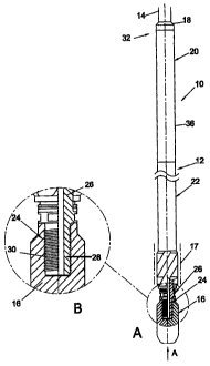
Referring initially to Fig. lA, there is shown a
longitudinal partial cross-sectional view of a downhole
tool assembly, in the form of a downhole drilling assembly
in accordance with a preferred embodiment of the present
invention and indicated generally by reference numeral 10.
The downhole drilling assembly 10 shown includes a
motor in the form of a turbine 12, coupled through drill
tubing 14 to surface for driving a drill bit 16 to drill a
wellbore 17. In general terms, the motor 12 defines a
first body of the assembly in the form of motor body 36,
and a second body of the assembly in the form of motor
power output drive shaft 26, mounted for rotation relative
to the motor body 36. A joint part in the form of a
selectively releasable joint is formed between the drive
shaft 26 and the drill bit 16, and locking means 34 are
provided for locking the drive shaft 26 relative to the
motor body 36, to prevent relative rotation therebetween,
as will be described below.
In more detail, the motor 12 includes, from top to
bottom, a tapered, pin-down, box-up connection 18 for
coupling to a lower end of the drill tubing 14; a
turbodrill power section comprising a turbine 20; a
turbodrill bearing section 22 and a safety joint part in
the form of a selectively releasable joint 24, for coupling
the drill bit 16 to a power output drive shaft 26 of the
turbine 20. It will be understood by persons skilled in
the art that the drive shaft 26 extends from the turbine
20, through the turbodrill bearing section 22 to the drill
bit 16, and that a drilling assembly in this form includes
CA 02434764 2003-07-14
WO 02/055838 PCT/GB02/00178
9
drill tubing 14 which is rotationally stationary during a
drilling operation. Rotation of the drill bit 16 is
effected by pumping drilling fluid, such as a drilling mud,
through the tubing 14 to the motor 12 and through the
turbine 20, to activate the turbine, rotating the drive
shaft 26 and drill bit 16.
The selectively releasable joint 24 is shown in more
detail in the enlarged view of Fig. 1B, and it will be seen
that the joint 24 comprises a cylindrical threaded pin 28
formed on a lower end of the drive shaft 26, and a
corresponding threaded box 30 formed in the drill bit 16
for receiving and engaging the pin 28 in a "pin-down"
fashion, as shown. It will be understood that the threads
on the pin 28 and box 30 are right-hand threads, such that
the bit 16 is made-up to the drive shaft 26 by rotating the
bit 16 relative to the shaft 26 in a clockwise direction,
when viewing in the direction of the arrow A in Fig. 1A, up
to a desired mating force, by applying a corresponding
torque.
In the mechanics of screw threads, the effort required
to raise a load is not the same as the effort required to
lower a load. This also applies to a screwed joint in that
the torque required to unscrew the joint is not the same as
the torque applied to make-up the joint. In most typical
joints, this difference is small and joints require
approximately the same torque to unscrew or "break out".
Referring now to Fig. 1C, which is a longitudinal,
partial cross-sectional view of part of a typical threaded
joint 25, if the lead (the distance the screw would advance
relative to, for example, a nut, in one rotation; for a
single thread screw, lead is equal to pitch) of the thread
is increased, the difference between the make up and break
out torques increases. Therefore, a significantly lower
break out torque can be achieved.
The selectively releasable joint 24 is configured such
CA 02434764 2003-07-14
WO 02/055838 PCT/GB02/00178
that the connection between the pin 28 and the box 30 by
the threads thereon is released by applying a release force
at a release torque less than the torque applied to make-up
the bit 16 to the shaft 26.
5 This is achieved by configuring the threads on the pin
28 and box 30 of joint 24 such that:
joint Coefficient of friction
1.0 < > 3
10 tan (helix angle)
where the tangent of the helix angle (a) is determined by:
lead
tan (a) =
2 11 rm
rm being the mean radius. The helix angle and pitch
(equal to lead for a single thread screw) is shown for the
typical pin 25 in Fig. 1C. The joint coefficient of
friction depends to a large extent upon the lubricant used
in the joint between the threads of the pin 28 and box 30,
the thread structure, and to a lesser extent, the pin
28/box 30 materials. The joint coefficient of friction for
the joint 24 may typically be in the range of 0.08 to 0.3.
The break-out torque is dependent upon the value of the
ratio of the joint coefficient of friction to the tan
(helix angle), such that the difference between the make-up
torque and the break-out torque is greatest when the ratio
is close to 1, and smallest close to 3. However, typically
the ratio will be around 2 for the joint 24, and the break
out torques will likely be in the range of 30-50% of make
up torque.
Thus, it will be understood that configuring the joint
24 in this fashion provides a safety joint where drill
CA 02434764 2003-07-14
WO 02/055838 PCT/GB02/00178
11
string connections between lengths of drill tubing 14
forming the string are of the normal type and break out at
a torque approximately the same as the make up torque; the
joint 24 is made with a special long lead thread according
to the above relationship and is made up to the same torque
as the other joints between the drill tubing 14 of the
string. However, when a reverse torque of in the range of
30-50% of the make up torque is applied to the string, the
string will "back out" (release) at the joint 24. In the
preferred embodiment shown in the drawings, a square
profile thread is employed.
Turning now to Fig. 2A, there is shown a longitudinal
cross-sectional view of an upper part 32 of the turbine 20
of the motor 12, which includes the connection 18 for
connecting the motor 12 to the drill tubing 14. Fig. 2A
shows in particular locking means in the form of a locking
assembly 34 provided at an upper end of the drive shaft 26
of the turbine 20. It will be understood that the turbine
is generally of a type known in the art, where the drive
20 shaft 26 acts as a rotor whilst a body 36 of the turbine 20
acts as a stator. Rotor blades 38 are provided spaced
axially along the length of the drive shaft 26 and stator
blades 40 are provided spaced along the length of the body
36. Drill fluid passing through the drill tubing 14 into
the turbine 20 in the direction of the arrow B (shown in
Fig. 2A) passes down between the rotor and stator blades
38, 40 to cause them to rotate relative to. one another,
thereby rotating the drive shaft 26 and drill bit 16.
Considering the locking assembly 34 in more detail,
the assembly is shown in Fig. 2A where a number of locking
members in the form of locking balls 42 have been inserted
through the drill tubing 14 for locking the drive shaft 26
against rotation relative to the body 36 of the turbine 20.
The locking balls 42 are shown in more detail in the
enlarged view of Fig. 2B.
CA 02434764 2003-07-14
WO 02/055838 PCT/GB02/00178
12
The locking assembly 34 further includes an
asymmetrical space 44, formed between an outer surface of
an upper end 46 of the drive shaft 26 and an inner surface
of a lower end 48 of a sub 50, which defines a box
connection 52 part of the coupling 18. The upper end 46 of
the drive shaft 26 includes a number of flats ( not shown),
and when the locking balls 42 are located as shown in Fig.
2A, they lie in the space 44. By an interaction between
the inner surface of lower end 48 of sub 50, the locking
balls 42 and the flats on the shaft upper end 46, further
rotation of the drive shaft 26 relative to the body 36 is
prevented and the drive shaft 26 is therefore locked.
The operation of the drilling assembly 10 and the
interaction between the various parts described above will
become clear from the following description of the use of
the assembly 10 in a well drilling operation.
The assembly 10 shown in Fig. 1A is made up at
surface, and run to drill a wellbore 17, in a fashion
apparent to the skilled person. During such drilling
operations, the drill bit 16 occasionally becomes "stuck",
such that further rotation and therefore deepening of the
wellbore 17, is not possible. Furthermore, this jamming of
the drill bit 16 causes the entire drilling assembly 10 to
become stuck. When this situation occurs, the locking
balls 42 are pumped down the drill tubing 14 from the
surface, as described above, and are located in the space
44, thereby locking the drive shaft 26 against further
rotation within and with respect to the body 36 of the
turbine 20. This allows the releasable joint 24 to be
"backed off", by applying a release torque through the
drill tubing 14 and the motor body 36. This is achieved by
rotating the assembly 10 in an anti-clockwise direction,
when viewing in the direction of the arrow A in Fig. 1A,
transmitting a release force to the releasable joint 24.
As the releasable joint 24 of the assembly 10 releases at
CA 02434764 2003-07-14
WO 02/055838 PCT/GB02/00178
13
a release torque which is lower than the torque required to
make-up the assembly, the drill bit 16 is released by a
separation of the pin 28 from the box 30, allowing the
remainder of the drilling assembly 10 to be recovered to
surface. It is this provision of a joint which releases at
a lower release torque which ensures that the assembly is
released at a desired location, that is, at a location
between the drill bit 16 and the drive shaft 26. This is
advantageous in that it both allows the drilling assembly
to be retrieved without having to abandon it in the
wellbore, and furthermore allows the drill bit 16 to be
recovered in a"fishing" operation (known in the art) , such
that the wellbore does not need to be sidetracked around
the stuck drill bit 16.
Turning now to Fig. 3A, there is shown a longitudinal,
partial cross-sectional view of a downhole drilling
assembly in accordance with an alternative embodiment of
the present invention, indicated generally by reference
numeral 100. The drilling assembly 100 is substantially
the same as the assembly 10 of Fig. 1A, and like components
share the same reference numerals incremented by 100. In-
fact, the difference between the assemblies 10 and 100 is
that the assembly 100 includes an alternative releasable
joint 124. The joint 124 couples the drill bit 116 to the
drive shaft 126 of turbine 120, and is shown in more detail
in Fig. 3B, which is an enlarged view of the joint 124 of
Fig. 3A. The joint 124 includes a crossover 54 and,
instead of providing the turbine shaft with a pin-down
connection, as in the assembly 10, the crossover includes
a cylindrical threaded pin 128 which engages a box 130
formed in a lower end of the drive shaft 126 and which
together form the releasable joint. Furthermore, the
crossover 54 includes a tapered threaded pin 56 which
engages a box 58 of bit 116, to form a standard tapered
threaded pin and box connection between the bit 116 and the
CA 02434764 2003-07-14
WO 02/055838 PCT/GB02/00178
14
crossover 54. The particular advantage of this arrangement
is that this allows drill bits (such as the bit 116) of a
standard type to be employed, with a standard box
connection 58, through the provision of the crossover 54.
Of course, when the joint 124 is released in a fashion
similar to that described above (by releasing the pin 128
from the box 130), both the bit 116 and the crossover 54
would be left in the wellbore, until such time as a fishing
operation may be conducted to retrieve the bit and
crossover.
In Fig. 4, there is shown a part of a downhole
drilling assembly in accordance with a further alternative
embodiment of the present invention, including a further
alternative selectively releasable joint, indicated
generally by reference numeral 224. Like components with
the assemblies 10 and 100 of Figs. 1A and 3A share the same
reference numerals incremented by 200. It will be
understood that only part of an assembly incorporating the
joint 224 is shown for clarity, as the remaining parts
carrying the joint 224 are similar to those of Figs. 1A and
3A.
The joint 224 includes a crossover 254 which includes
a cylindrical threaded pin 228, coupled to a corresponding
threaded box 230 in drill bit 216, to form the selectively
releasable joint 224. The crossover 254 is coupled to a
lower end of drive shaft 226 of a turbine (not shown) by a
standard tapered threaded pin and box connection, which
includes a pin 60 formed on the crossover 254 and a
corresponding box 62 formed in the lower end of the drive
shaft 226. It will be understood that this is advantageous
in that the arrangement allows drilling motors such as
turbines to be provided which have standard type drive
shafts 266, carrying standard box connections, with the
releasable joint formed"between the crossover 254 and the
bit 216.
CA 02434764 2003-07-14
WO 02/055838 PCT/GB02/00178
Fig. 5 shows a still further alternative selectively
releasable joint, indicated generally by reference numeral
324. Like components of the joint 324 with the assemblies
of Figs. 1A-4 share the same reference numerals incremented
5 by 300. In a similar fashion to the joint 224 shown in
Fig. 4, it will be understood that, for clarity, the
remainder of a drilling assembly carrying the joint 324 is
not shown.
The joint 324 comprises first and second bodies
10 forming a crossover assembly and having a crossover 354 and
a lower sub 64. The crossover 354 includes a tapered
threaded pin 360 for connection to a drive shaft of a
turbine (not shown), in a similar fashion to the crossover
254 of Fig. 4, and a cylindrical threaded pin 328 for
15 engaging a corresponding threaded box 330 in the sub 64, to
together define the releasable joint in the crossover
assembly. The sub 64 also includes a tapered threaded pin
356 for engaging a corresponding box in a drill bit (not
shown), in a similar fashion to the crossover 124 of Fig.
3A, which engages drill bit 116. The arrangement is
particularly advantageous in that it both allows the use of
standard turbine drive shafts and drill bits through
standard tapered threaded pin and box connections. It will
be understood that in the event of a drill bit coupled to
a drive shaft through such a releasable joint 324 becoming
struck, release of the drill bit is achieved by separating
the pin 328 from the box 330 by applying a released torque
in the fashion described above through the turbine drive
shaft and the crossover 354.
It will be understood that references herein to a
drilling motor and to a motor include any suitable device
for generating a rotational drive force in a downhole
environment, and include but are not limited to turbines,
PDM's, electric motors and the like.
Various modifications may be made to the foregoing
CA 02434764 2003-07-14
WO 02/055838 PCT/GB02/00178
16
within the scope of the present invention. In particular,
the joints 24, 124, 224, 324 may include threads of a
modified square (5-10 ) profile; however, other thread
profiles may be employed with perhaps, less efficient
operational characteristics. The downhole tool, although
of particular benefit in the disclosed uses, may be used in
any suitable downhole tool assembly where it is desired to
release a part of the assembly in the event of the assembly
becoming stuck as described above, and thus the downhole
tool is not limited to use in a drilling assembly. It will-
be understood that the term "joint coefficient of friction"
used herein is a term known in the art, as used, for
example, by the American Petroleum Institute.