Note: Descriptions are shown in the official language in which they were submitted.
CA 02434994 2003-07-04
WITHDRAWAL OF SAMPLES
Field of the Invention
The invention concerns an arrangement for the withdrawal of samples from a
flow
of harvested crop flowing in a conveying channel in a harvesting machine.
Background of the Invention
in agriculture, there is an interest in obtaining information about quality
parameters of harvested crop. Several parameters of the harvested crop can
already be detected during the harvesting process, such as moisture, as is
described, for example, by EP 0 908 086 A on the basis of a combine. For the
determination of some other parameters of the harvested crop, such as the
percentage of amylum, the withdrawal of samples for later analysis in a
laboratory is
useful. Here an automation is desirable.
FR 2 801 380 A describes an automatic sample withdrawal arrangement for a
combine. In the grain elevator, an opening is provided that can be
repositioned and
closed through which grain trickles to a conveyor that fills it into a hose.
By clamping
off sections of the hose, individual samples are generated, the location of
whose
origin can be detected by a satellite-supported position detection system.
information regarding the position and the number of the sample is stored in a
data
bank for later identification.
According to the disclosures of EP 0 908 086 A and FR. 2 807 380 A, one part
of a
flow of crop trickles through an opening and is then collected until a
sufficient amount
is available as a sample. Since the sample is taken out of the crop flow on
the basis of
its gravity, problems can occur when the crop contains a high degree of
moisture. For
example, the withdrawal of silage from the flow of the crop of a forage
harvester can
not successfully be accomplished using these solutions.
Summary of the Invention
The problem underlying the invention is seen in the need for an improved
sample
withdrawal arrangement.
An object of the invention is to provide an arrangement for withdrawing a
sample
from a stream of harvested crop by selectively inserting a guide or deflector
into the
stream so as to cause a sample of the crop to move to a collection station.
In this way a region of the guide element is inserted into the flow of the
crop with
the result that the harvested crop is forced to deflect. The resulting jam
provides the
CA 02434994 2003-07-04
assurance that harvested crop is actually withdrawn from the conveying
channel. An
appropriate selection of the size of the guide element can provide the
assurance that
a representative sample of the entire cross section of the flow of the
harvested crop
can be withdrawn.
One solution is to attach the guide element so that it can pivot freely.
Thereby, it
can be moved between a sample withdrawal position and a non-operating
position.
In the non-operating position, it preferably closes an opening in a wall of
the
conveying channel, so that an undisturbed flow of the harvested crop is
possible. In
the sample withdrawal position, it frees the opening, and a region of the
guide
element extends into the flow of the harvested crop. The deflected flow of the
harvested crop as a rule then flows through the opening. The pivot axis of the
guide
element extends appropriately at least approximately transverse to the
direction of
the flow of the crop. Embodiments are also conceivable with a (exclusively or
additionally) movable guide element that can be slid into the conveying
channel and
slid out of it again.
Fundamentally, it would be conceivable to attach the guide element to the wall
of
the conveying channel, pivoted at one end. However, the arrangement of the
pivot
axis approximately at the center of the guide element (relative to the
direction of flow
of the crop in the conveying channel) is particularly appropriate. Thereby,
the guide
element can be used from two sides. If one side is worn after prolonged use,
the
guide element can be turned, or both sides are used alternately and thereby
wear-
iife is extended. Furthermore, there is the possibility of using a rotary
drive with a
single direction of rotation.
'There are various possibilities regarding the positioning of the region of
the guide
element that can be inserted into the conveying channel. In a first
embodiment, this
region is arranged at an angle of less than 90° to the direction of
flow of the crop.
With a guide element that can be pivoted, it is then arranged upstream of the
pivot
axis of the guide element. Thereby the crop maintains its direction of flow,
at least
approximately, even when the guide element is in the sample withdrawal
position. -It
is, however, deflected through a certain angle. In another embodiment, the
region of
the guide element extending into the conveying channel in the sample
withdrawal
2
CA 02434994 2003-07-04
position is oriented transverse to the direction of flow of the harvested
crop, or the
angle between the guide element and the direction of flow is even greater than
90°.
In the case of a guide element that can be pivoted, the aforementioned region
is then
located downstream of the pivot axis of the guide element. A jam of the
harvested
crop then develops that leads to the crop reaching out of the conveying
channel for
the withdrawal of the sample.
In order to withdraw a greater number of samples on larger fields, an
automation
of the sample withdrawal process is a solution. For this purpose, a drive for
the
pivoting of the guide element about its pivot axis driven by outside force and
an
appropriate means for inserting the sample of the harvested crop withdrawn
from the
flow of the crop into a sample container are appropriate. An appropriate
control
arrangement controls the drive that brings about the insertion of the guide
element
into the conveying channel on the basis of a manual input or when pre-
determined
points in time and/or locality are passed, at which the guide element is
pivoted. The
harvested crop that was withdrawn reaches a sample container by means of a
conveyor or its own kinetic energy. The actual position of the guide element
can be
monitored by appropriate sensors. These provide assurance that the sample was
actually taken and that the guide element is subsequently returned to its non-
operating position.
Preferably, information is stored, for example, in a data bank on the basis of
which the particular sample container can later be identified. For example, a
printing
of the sample container with corresponding information is conceivable, such
as, for
example, a bar code or the storing of the information in a transponder
connected to
the container. It would also be conceivable to store a sample container number
or
information about the position at which the sample container is located in a
data
bank. Also, the origin of the location at which the sample was taken may be
determined by a position detection system - preferably satellite supported -
(or
another magnitude on the basis of which the sample can later be identified,
such as
the time of its generation) can be stored in memory or imprinted on the sample
container. Instead of storing the sample in a sample container arid to analyze
it later
in a laboratory, an on-the-spot analysis by means of appropriate implements
would
3
CA 02434994 2003-07-04
also be possible.
The invention is appropriate for any harvesting machine in which the harvested
crop flows through a conveying channel, for example, balers, self-loading
forage
boxes, combines or forage harvesters. In the case of the latter, the guide
arrangement is preferably arranged in the discharge duct.
Brief Description of the Drawincts
The drawing shows two embodiments of the invention that shall be described in
greater detail in the following.
FIG. 1 shows a schematic left side view of a harvesting machine of the type
with
which the invention is useful.
FIG. 2 shows the discharge duct of the harvesting machine incorporating a
first
embodiment of a guide element for the withdrawal of a sample from the duct.
FIG. 3 shows the discharge duct of the harvesting machine incorporating a
second
embodiment of a guide element attached to it for the withdrawal of a sample.
Description of the Preferred Embodiment
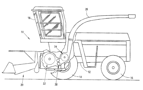
Referring now to FIG. 1, there is shown a harvesting machine 10, in the form
of a
self-propelled forage harvester, supported on a frame 12 that is carried by
front and
rear wheels 14 and 1 G. The harvesting machine 10 is controlled from an
operator°s
cab 18 from which a crop take-up arrangement 20 can be controlled while being
within view of the operator. Crop, for example, corn, grass, or the like,
taken up from
the ground by means of the crop take-up arrangement 20 is conducted to a
chopper
drum 22 that chops it into small pieces and delivers it to a conveyor
arrangement 24.
The crop leaves the harvesting machine 10 to an accompanying trailer through a
discharge duct 26 that is mounted for swinging about an upright pivot axis. A
post-
chopper reduction arrangement or kernel processor 28 is located between the
chopper drum 22 and the conveyor arrangement 24 through which the crop to be
conveyed is conducted tangentially to the conveyor arrangement 24.
FIG. 2 shows a vertical section along the discharge duct 26. An opening 30 is
provided in the upper wall of the discharge duct 26. Within the opening 30, a
guide
element 32 is located that takes the form of a $lat sheet metal plate that is
supported
in bearings so as to pivot about a pivot axis 34 extending horizontally and
transverse
4
CA 02434994 2003-07-04
to the plane of the drawing. In plan view, the guide element 32 may be
circular or
rectangular in shape. Relative to the direction of the flow of the crop, that
is
indicated by the arrow 36, the pivot axis extends through the center of the
guide
element 32. A drive 38, actuated by outside force, in the form of an electric
or
hydraulic motor using transmission elements, not shown, selectively causes a
rotation of the guide element 32 about the pivot axis 34. FIG. 2 shows the
guide
element 32 in its sample withdrawal position in which the harvested crop
flowing
through the discharge duct 26 impinges upon the region of the guide element 32
at
an angle of approximately 45°, which region is located (relative to the
flow of the
crop) upstream of the pivot axis 34. Crop which impinges on this region of the
guide
element 32 is deflected upward by the guide element 32, so that it reaches a
sample
container 40. The guide element 32 can be brought into a non-operating
position, by
the drive 38, in which it extends parallel to the adjoining wall of the
discharge duct 26
and closes the opening 30. The sample container 40 may be, for example, a
bottle,
a paper bag or a box. The sample container 40 is extracted from a magazine by
an
arrangement, not shown, for example, a gripping arm, and is returned to the
magazine after being filled with the sample of the harvested crop. An
electronic
control assigns a place for the sample container 40 in the magazine, for
correspondence to that location at which the sample was taken, for later
evaluation.
The use of a hose as suggested in FR 2 801 380 A would also be conceivable for
the retention of the sample.
FIG. 3 shows a second embodiment of a guide element 32. Flements
corresponding to those of the first embodiment are given the same number call-
outs.
However, FIG. 3 shows a horizontal section along the discharge duct 26. The
discharge duct includes the two side walls shown in FIG. 1. In one of these,
the
opening 30 is provided for the guide element 32, that can pivot about the
pivot axis
34 extending vertically. In the sample withdrawal position shown, the region
of the
guide element 32, extending into the interior of the discharge duct 2fi, is
arranged
downstream of the pivot axis 34 relative to the flow of the harvested crop.
The
harvested crop impinges upon the guide element 32 at an angle of approximately
135°. Here, a back-draft develops that results in the harvested crop
reaching the
CA 02434994 2003-07-04
sample container 40. In this embodiment, the drive 38 is also arranged to
bring the
guide element 32 into a non-operating position, in which it extends parallel
to an
adjoining wall of the discharge duct 26 and closes the opening 30.
The arrangement, according to the invention shown here, makes it possible to
withdraw samples automatically from the discharge duct 26 of the harvesting
machine 10 that takes the form of a forage harvester. These samples are
fundamentally important for the development of calibrations of NiR measurement
systems. Furthermore a GE~-referenced sample withdrawal of test strips is
possible
during the harvest. In addition, the owner is offered the possibility of
checking the
accuracy of a moisture content measuring system or a control system for
quality
parameters of the harvested crop and, if necessary, to calibrate these anew.
Having described the preferred embodiment, it will become apparent that
various
modifications can be made without departing from the scope of the invention as
defined in the accompanying claims.
6