Language selection

Search

Patent 2435134 Summary

Third-party information liability

Some of the information on this Web page has been provided by external sources. The Government of Canada is not responsible for the accuracy, reliability or currency of the information supplied by external sources. Users wishing to rely upon this information should consult directly with the source of the information. Content provided by external sources is not subject to official languages, privacy and accessibility requirements.

Claims and Abstract availability

Any discrepancies in the text and image of the Claims and Abstract are due to differing posting times. Text of the Claims and Abstract are posted:

  • At the time the application is open to public inspection;
  • At the time of issue of the patent (grant).
(12) Patent: (11) CA 2435134
(54) English Title: DISPLAY STAND WITH FOLDABLE SELF ERECTING SUPPORTING BASE
(54) French Title: PRESENTOIR AVEC BASE SUPPORT AUTODEPLIABLE
Status: Deemed expired
Bibliographic Data
(51) International Patent Classification (IPC):
  • A47F 5/16 (2006.01)
  • A47F 5/11 (2006.01)
  • G09F 5/00 (2006.01)
(72) Inventors :
  • MOSS, GEOFFREY A. (Canada)
  • MINISTER, DAVID B. (Canada)
(73) Owners :
  • POPTECH LIMITED (Canada)
(71) Applicants :
  • MOSS, GEOFFREY A. (Canada)
  • MINISTER, DAVID B. (Canada)
(74) Agent:
(74) Associate agent:
(45) Issued: 2013-02-05
(22) Filed Date: 2003-07-10
(41) Open to Public Inspection: 2005-01-10
Examination requested: 2008-06-19
Availability of licence: N/A
(25) Language of filing: English

Patent Cooperation Treaty (PCT): No

(30) Application Priority Data: None

Abstracts

English Abstract

A display stand has supporting base which is self erecting by a pivotal board located within the base. The pivotal board is biassed by an elastic cord and is pivotable between a horizontal position transverse to the base and a vertical downward position at which it is juxtaposed to the front panel of the base. The pivotal board is engageable with a horizontal slot opening formed in the rear panel of the base for maintaining the base in the erected condition. The side panels of the base are also foldable inwards along two vertical fold lines formed in the middle therein. A second elastic cord is connected between these fold lines so that it would pull the side panels to fold inwards at the vertical fold lines when the pivotal board is pulled downwards to disengage from the horizontal slot opening. A display tray is disposable in a forward sloping position on the base and the base in the collapsed folded condition may be placed within the tray for shipping, transporting, or storage.


French Abstract

Un présentoir de plancher comporte une base qui est autodépliable grâce au panneau pivotant qu'elle renferme. Le panneau pivotant est sollicité par un cordon élastique et peut pivoter entre une position horizontale transversale à la base et une position descendante verticale à laquelle il est juxtaposé au panneau avant de la base. Le panneau pivotant s'enclenche dans une fente horizontale du panneau arrière de la base afin de maintenir cette dernière en position dépliée. Les panneaux latéraux de la base sont également pliables vers l'intérieur le long de deux lignes de pli verticales formées au milieu de ceux-ci. Un deuxième cordon élastique est fixé entre ces lignes de pli de manière à tirer les panneaux latéraux vers l'intérieur aux lignes de pli verticales lorsqu'on tire sur le panneau pivotant vers le bas pour le dégager de la fente horizontale. Un plateau de présentation est posé en position inclinée vers l'avant sur la base et cette dernière, en position repliée, peut être placée dans le plateau pour l'expédition, le transport ou l'entreposage.

Claims

Note: Claims are shown in the official language in which they were submitted.


The embodiments of the invention in which an exclusive property or privilege
is claimed
are defined as follows:


1. A display stand comprising,

a hollow foldable self erecting supporting base having a front panel, a rear
panel, and two
opposite side panels,

a central vertical fold fine formed at said side panels and extending the
entire height of said
side panels,

a horizontal fold line formed around said base and located at a same
horizontal plane of all of
said front panel, said rear panel and said side panels,

a pivotal board located within said base and positioned below said horizontal
fold line, said
pivotal board having one edge therein attached to said front panel and being
pivotable relative to
said front panel to locate between a horizontal position crosswise to said
base, and a vertical
downward position juxtaposed to said front panel,

an elongated elastic cord having one end attached to a narrow free end portion
of said pivotal
board and another end attached to an upper edge portion of said rear panel,
said elastic cord being
extensible in an elastic tension when said pivotal board is in said vertical
downward position,

a horizontal slot opening formed in said rear panel and located below said
horizontal fold line,
said slot opening being engageable with said narrow free end portion of said
pivotal board for
maintaining said base in an erected condition,

an operating opening formed in said pivotal board and located adjacent to said
narrow free end
portion therein, said pivotal board being pivotable by inserting a finger
through said operating
opening and pulling said pivotal board to pivot downward to said vertical
downward


-7-


position for creating said elastic tension in said elastic cord,

a display tray disposable on top of said base when said base is in said
erected condition, and
said rear panel having a taller height than said front panel, and said side
panels having sloping top
edges sloping from a top edge of said rear panel to a short distance below a
top edge of said front
panel whereby an upstanding lip portion is formed at said top edge of said
front panel, said

upstanding lip portion providing an abutment for a front edge of said display
tray when said tray is
disposed on said base in a downward sloping position.

2. A display stand according to Claim 1 wherein said side panels are foldable
inwards towards
one another when said pivotal board is in said downward vertical position to
fold said base into a
collapsed condition.

3. A display stand according to Claim 2 wherein said base is foldable along
said horizontal fold
line when said base is in said collapsed condition whereby said base is
placeable within said
display tray for shipping, transporting and storage.

4. A display stand according to Claim 2 wherein said base is self erecting to
said erected
condition when said base is unfolded from said collapsed condition along said
horizontal fold line
whereby said elastic tension of said elastic cord automatically pulls said
pivotal board to said
crosswise position with said narrow free end portion therein engaged with said
horizontal slot
opening in said rear panel.

5. A display stand according to Claim 4 including a second elastic cord
connected between said
vertical fold line of said side panels and located above said pivotal board,
said second elastic cord
being in elastic tension when said base is in said erected condition, and
being operative

automatically to pull said side panels inwards towards one another when said
pivotal board is in

-8-


said downward vertical position.
6. A display stand comprising,

a hollow foldable self erecting supporting base made of a single card board
material, said base
having a front panel, a rear panel, and two opposite side panels, and said
base having a larger
bottom end than a top end therein,

a central vertical fold line formed in said side panels and extending the
entire vertical length
therein,

a horizontal fold line formed around said base and located at a same
horizontal plane of all of
said front panel, said rear panel, and said side panels,

said rear panel having a height taller than said front panel, and said side
panels having slanted
top edge sloping from a top edge of said rear panel to a short distance below
a top edge of said
front panel whereby forming an upstanding top lip portion at said top edge of
said front panel,

a trapezoidal shaped pivotal board located within said base and said pivotal
board having a
bent front edge attached to said front panel and a free rear end portion
distal from said bent front
edge, said pivotal board being pivotable selectively relative to said front
panel to locate at a
horizontal position transverse to said base, and at a vertical downward
position juxtaposed to
said front panel,

a horizontal slot opening formed in said rear panel and located below said
horizontal fold line,
said slot opening being engageable with said free rear end portion of said
pivotal board when said
pivotal board is in a transverse position for maintaining said base in an
erected condition,

a first elastic cord having one end connected adjacent to said free rear end
portion of said
pivotal board and another end connected to a location just below said top edge
of said rear panel,

-9-


an operating opening formed in said pivotal board and located adjacent to said
free rear end
portion therein, said pivotal board being pivotable between said transverse
position and said
vertical downward position by inserting a finger into said operating opening
and pulling said
pivotal board to engage with said horizontal slot opening and then pivoting
downward against
elastic tension of said first elastic cord to move to said downward vertical
position whereby said
side panels are foldable inwards towards one another to fold said base into a
collapsed condition,

a rectangular display tray disposable on said base when said base is in said
erected condition.
7. A display stand according to Claim 6 including a second elastic cord
connected between said
vertical fold line of said side panels and located above said pivotal board,
said second elastic cord
being in elastic tension when said base is in said erected condition, and said
second elastic cord
being operative to pull said side panels inwards towards one another when said
pivotal board is
pulled downwards to disengage with said horizontal slot opening of said rear
panel.

8. A display stand according to Claim 7 wherein said upstanding lip portion at
said top edge of
said front panel serves as an abutment to a front edge of said display tray
when said tray is
disposed in a forward sloping position on said base.

9. A display stand according to Claim 8 including a pivotal flap formed at
said top edge of said
rear panel, and mounting pads located on said pivotal flap, said mounting pads
being engageable
with associated mounting pads located at the underside of said display tray
when said tray is
disposed on said base in said erected condition for removably attaching said
tray to said base.

10. A display stand according to Claim 9 wherein said base in said collapsed
condition is
further foldable along said horizontal fold line whereby said base is
placeable within said display
tray for shipping, transporting and storage.


-10-


11. A display stand according to Claim 10 wherein said base is self erecting
when unfolded
relative to said horizontal fold line whereby said pivotal board pivots from
said vertical downward
position to said transverse position by said elastic tension of said first
elastic cord.


-11-

Description

Note: Descriptions are shown in the official language in which they were submitted.


CA 02435134 2003-07-10

DISPLAY STAND WITH FOLDABLE SELF ERECTING SUPPORTING BASE

This invention relates to a display stand having a tray and a self erecting
supporting base
which is also foldable in a collapsed condition for packing with merchandise
in the tray for
shipping, transporting and storage.

Display stands made of cardboard or corrugated board material are commonly
used for
displaying merchandise. Such display stands have either a flat top or a tray
for displaying the
merchandise. The top is supported by a base which may be folded over or under
the tray for
storage or transportation. The base is often attached to or integrally formed
with the tray such
that the display stand is formed readily when the base is erected. Such
display stands are shown

in U. S. No. 2, 066, 844 to H. E. Lynch; U. S. Patent No. 3, 300, 166 to W. P.
Wojciechowski; U.
S. Patent No. 4, 582, 283, to P. Schmitt; and U. S. Patent No. 4, 813, 536 to
W. T. Willis. The
main drawback of such display stands is that the base must be manually and
painstakingly
unfolded and erected at the merchandise display location. This process is
often rather awkward
and frustrating to carry out due to the stiffness of the cardboard material
which renders the base
difficult to unfold and to erect.

Attempts have been made to provide a self erecting base attached to the
underside of the
merchandise packing tray such that the base can be erected by simply lifting
the tray upwards.
Such display stand is shown in U. S. Patent No. 4, 726, 476 to J. S. Smith.
However, the self
erecting operation of the base of such construction is problematic because the
folded base tends

to retain its collapsed shape permanently and it could not be unfolded by its
self erecting
mechanism. This problem is particularly severe when the folded base is
compressed for a
relatively lengthy period of time by the weight of the merchandise packaged in
the tray.

-1-


CA 02435134 2003-07-10

It is a principal object of the present invention to provide a display stand
having a self
erecting base in which the self erecting mechanism is effective in unfolding
and erecting the
base.

It is another object of the present invention to provide a display stand in
which the

display tray is usable for packing, the merchandise as well as the base folded
in the collapsed
condition.

It is another object of the present invention to provide a display stand in
which the
display tray may be removably attached to the base so that the base may be
easily separated from
the tray for folding and packing it within the tray thereafter.

In the drawings,

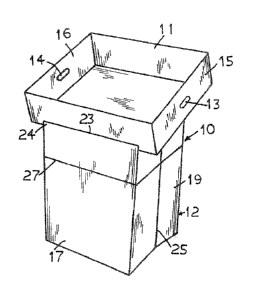
Figure I is a perspective elevation view of the display stand of the present
invention in
the erected condition.

Figure 2 is a bottom perspective elevation view of the tray with the tray
showing the
provision of attaching means which is operative for removably attaching the
tray to the base.
Figure 3 is a top perspective elevation view of the base with the tray removed
showing

the elastic biassed trapezoidal shape pivotal board of the self erecting
mechanism.

Figure 4 is a top perspective elevation view of the base with the tray removed
and with
the pivotal board pulled downwards and the side panel pulled partially inwards
by the biassing
elastic cord connected between the side panels.

Figure 5 is a front perspective elevation view showing the base in a collapsed
condition.
Figure 6 is a perspective elevation view of the tray with the folded base
fully located
therein.

-2-


CA 02435134 2003-07-10

With reference to the drawings, the display stand 10 of the present invention
has a
display tray 11 disposed on top of a substantially rectangular base 12. The
tray 11 may be used
for packing the merchandise for transportation, shipping, and for displaying
the merchandise
when the stand is erected. The tray 11 is generally rectangular in shape and
is provided with two

handle openings 13 and 14 on two opposite side walls 15 and 1.6 respectively
to facilitate its
handling.

The base 12 has a generally rectangular horizontal cross sectional shape and
it may be
slightly larger at the bottom and tapering upwards to a smaller top end so as
to provide better
stability when the base is standing on a supporting surface. The front panel
17 is shorter in

height than the rear panel 18, such that when the tray 11 is placed on the
stand it may be in a
slanted position to provide a better view of the merchandise displayed
therein. The two side
panels 19 and 20 have sloping top edges 21 and 22 sloping from the top comers
of the taller rear
panel 18 to a location slightly below the top edge 23 of the shorter front
panel 17 such that a
short upstanding lip 24 of the front panel 17 extends above the front corners
of the side panels

19 and 20. The upstanding lip 24 serves as an abutment for the front edge of
the tray 10 when
the latter is placed on the base.

Two vertical fold lines 25 and 26 are provided at the middle of the side
panels 19 and 20
respectively and they extend the entire length of these side panels such that
the side panels 19
and 20 may be pushed inwards at these vertical fold lines, as best shown in
figure 4, to fold the

base into a collapsed condition with the front panel 17 lying juxtaposed to
the rear panel 18. A
horizontal fold line 27 is provided all around the base 12 and located in
horizontal plane at a
short distance from the top edges of the front, rear, and side panels such
that the base 12 in the

-3-


CA 02435134 2003-07-10

collapsed condition may be further folded along the horizontal fold line 27 as
best shown in
Figures 5 and 6. In this collapsed and folded condition, the base 12 may be
conveniently packed
within the tray 10 as shown in Figure 6.

A generally trapezoidal shaped wedge pivotal board 28 is located in a
horizontal manner
in the base 12. The pivotal board 28 has a dimension similar to the horizontal
cross section
dimension of the base 12 when the latter is in. the erected condition. The
wider front edge 29 of
the pivotal board 28 is attached to the front panel 17 such that it is
pivotable relative to the front
panel as shown by the dotted line in Figure 3. The length of the pivotal board
28 is longer than
the width of the side panels 19 and 20 when the latter are in the erected
condition. A horizontal

slot opening 30 is formed in the rear panel 18 in a location slightly below
the horizontal fold line
27. A narrower rear end portion 31 of the pivotal board 28 will engage with
the slot opening 30
to hold the pivotal board 28 in the generally horizontal position so as to
maintain the base 12
securely in the erected condition.

An operating opening 32 is formed in the pivotal board 28 at a location
adjacent to the
narrower rear end portion 31 and an elongated elastic cord 33 is attached at
one end to the rear
end portion 31 of the pivotal boars 28 and at the other end to a location
adjacent to the top edge
34 of the rear panel 18. The elastic cord 33 is in the relax condition when
the pivotal board 28 is
located in the horizontal position with its rear end portion 31 engaged with
the slot opening 30
of the rear panel 18. The base 12 may be folded to the collapsed condition by
inserting a finger
into the operating opening 32 and pulling the pivotal board 28 to disengage
from the slot

opening 30 and then pivoting downwards towards the front panel 17 as shown in
the dotted line
in Figure 3, and in the meantime, pushing the side panels 19 and 20 inwards at
the vertical fold
:4_


CA 02435134 2011-11-30

lines 25 and 26 until the base 12 is in the collapsed condition.

A second elastic cord 34 may be mounted between the side panels 19 and 20 and
locating
above the pivotal board 28 and extending between and connected to the vertical
fold lines 25

and 26. The elastic cord 34 is in tension when the base 12 is in the erected
condition, so that
when the pivotal board 28 is pivoted downwards, the tension of the elastic
cord 34 will
automatically pull the side panels 19 and 20 inwards towards one another, as
best shown by the
arrows in Figure 4, so as to facilitate the folding of the base to the
collapsed condition. In the
erected condition of the base, the pivotal board 28 prevents the side panels
19 and 20 from being
pulled inwards by the second elastic cord 34. The base 12 in the collapsed
condition may further

be folded along the horizontal fold line 27 as shown in Figures 5 and 6, so
that it may be
conveniently placed and packed in the tray 10 as shown in Figure 6 with the
merchandise for
shipping, transporting, or storage.

An extension flap 35 pivotable relative to the top edge 34 of the rear panel
18 may
extend outwards from the top edge. Mounting pads 36 and 37 having a plurality
of fine hair-like
clinging forgers such as VELCRO (trade mark) pads may be provided on the
surface of the

extension flap 35 and the associated mounting pads 38 and 39 as shown in
Figure 2 also provided
on the underside of the tray 10 such that the mounting pads and the associated
mounting pads
cooperate to secure the tray 10 resting safely and removably on the base 12.

The base 12 may be erected from the collapsed condition by simply unfolding it
from the
horizontal fold line 27. The tension in the elastic cord 33 will automatically
pull the pivotal
board 28 back to the horizontal position until its rear end portion 31 engages
with the slot
opening 30. Since the dimension of the pivotal board 28 is same as the cross
sectional dimension

-5-


CA 02435134 2003-07-10

of the base in the erected condition, the pivotal board 28 would push the side
panels 19 and 20
outwards against the elastic force of the elastic cord 39 until the base 12 is
in the erected
condition and it will maintain the base 12 rigidly in such erected condition.

The present invention may be carried out with various modifications without
departing
5. from the spirit or essential attributes thereof, and accordingly, reference
should be made to the
appended claims, rather than to the foregoing specification as indicating the
scope of the
invention.

15

Representative Drawing
A single figure which represents the drawing illustrating the invention.
Administrative Status

For a clearer understanding of the status of the application/patent presented on this page, the site Disclaimer , as well as the definitions for Patent , Administrative Status , Maintenance Fee  and Payment History  should be consulted.

Administrative Status

Title Date
Forecasted Issue Date 2013-02-05
(22) Filed 2003-07-10
(41) Open to Public Inspection 2005-01-10
Examination Requested 2008-06-19
(45) Issued 2013-02-05
Deemed Expired 2020-08-31

Abandonment History

There is no abandonment history.

Payment History

Fee Type Anniversary Year Due Date Amount Paid Paid Date
Application Fee $150.00 2003-07-10
Maintenance Fee - Application - New Act 2 2005-07-11 $50.00 2005-06-30
Maintenance Fee - Application - New Act 3 2006-07-10 $50.00 2006-05-11
Registration of a document - section 124 $100.00 2006-08-15
Maintenance Fee - Application - New Act 4 2007-07-10 $50.00 2007-05-15
Maintenance Fee - Application - New Act 5 2008-07-10 $100.00 2008-06-02
Request for Examination $400.00 2008-06-19
Maintenance Fee - Application - New Act 6 2009-07-10 $100.00 2009-06-08
Maintenance Fee - Application - New Act 7 2010-07-12 $100.00 2010-05-14
Maintenance Fee - Application - New Act 8 2011-07-11 $100.00 2011-06-22
Maintenance Fee - Application - New Act 9 2012-07-10 $100.00 2012-06-18
Final Fee $150.00 2012-11-26
Maintenance Fee - Patent - New Act 10 2013-07-10 $125.00 2013-06-25
Maintenance Fee - Patent - New Act 11 2014-07-10 $125.00 2014-06-27
Maintenance Fee - Patent - New Act 12 2015-07-10 $125.00 2015-02-18
Maintenance Fee - Patent - New Act 13 2016-07-11 $125.00 2016-06-27
Maintenance Fee - Patent - New Act 14 2017-07-10 $125.00 2017-06-28
Maintenance Fee - Patent - New Act 15 2018-07-10 $225.00 2018-06-29
Maintenance Fee - Patent - New Act 16 2019-07-10 $225.00 2019-05-29
Owners on Record

Note: Records showing the ownership history in alphabetical order.

Current Owners on Record
POPTECH LIMITED
Past Owners on Record
MINISTER, DAVID B.
MOSS, GEOFFREY A.
Past Owners that do not appear in the "Owners on Record" listing will appear in other documentation within the application.
Documents

To view selected files, please enter reCAPTCHA code :


To view images, click a link in the Document Description column. To download the documents, select one or more checkboxes in the first column and then click the "Download Selected in PDF format (Zip Archive)" or the "Download Selected as Single PDF" button.

List of published and non-published patent-specific documents on the CPD .

If you have any difficulty accessing content, you can call the Client Service Centre at 1-866-997-1936 or send them an e-mail at CIPO Client Service Centre.


Document
Description 
Date
(yyyy-mm-dd) 
Number of pages   Size of Image (KB) 
Office Letter 2021-05-25 2 189
Office Letter 2021-05-26 2 208
Abstract 2003-07-10 1 43
Description 2003-07-10 6 370
Claims 2003-07-10 5 317
Drawings 2003-07-10 3 101
Representative Drawing 2003-10-10 1 16
Cover Page 2004-12-20 1 49
Description 2011-11-30 6 343
Claims 2011-11-30 5 207
Claims 2012-06-21 5 194
Representative Drawing 2013-01-14 1 14
Cover Page 2013-01-14 2 53
Correspondence 2008-03-26 2 42
Assignment 2003-07-10 2 123
Maintenance Fee Payment 2017-06-28 1 45
Fees 2005-06-30 1 36
Assignment 2006-08-15 6 202
Prosecution-Amendment 2008-01-22 1 51
Prosecution-Amendment 2008-06-19 3 99
Maintenance Fee Payment 2018-06-29 1 36
Prosecution-Amendment 2011-06-10 2 96
Prosecution-Amendment 2011-11-30 8 320
Prosecution-Amendment 2012-03-13 2 44
Maintenance Fee Payment 2019-05-29 2 74
Prosecution-Amendment 2012-06-21 7 256
Correspondence 2012-11-26 1 41
Correspondence 2012-12-06 1 12
Correspondence 2013-03-14 1 13
Maintenance Fee Payment 2016-06-27 1 40