Note: Descriptions are shown in the official language in which they were submitted.
CA 02435179 2004-03-16
-1-
SELF-CENTERING MAGNET ASSEMBLY FOR USE IN
A LINEAR TRAVEL MEASUREMENT DEVICE
FIELD OF THE INVENTION
The present invention generally relates to linear travel
measurement devices.
BACKGROUND OF THE INVENTION
In the control of fluid in industrial processes, such as oil
and gas pipeline systems, chemical processes, etc., it is often
necessary to reduce and control the pressure of a fluid. Regulators
are typically used for these tasks by providing adjustable flow
restriction through the regulator. The purpose of the regulator in
a given application may be to control flow rate or other process
variables, but the restriction inherently induces a pressure
reduction as a by-product of its flow control function.
By way of example, a specific application in which regulators
are used is the distribution and transmission of natural gas. A
natural gas distribution system typically includes a piping network
extending from a natural gas field to one or more consumers . In
order to transfer large volumes of gas, the gas is compressed to an
elevated pressure. As the gas nears the distribution grid and,
ultimately, the consumers, the pressure of the gas is reduced at
pressure reducing stations. The pressure reducing stations
typically use regulators to reduce gas pressure.
It is important for natural gas distribution systems to be
capable of providing sufficient volumes of gas to the consumers.
The capacity of this system is typically determined by the system
pressure, piping size, and the regulators, and system capacity is
often evaluated using a simulation model. The accuracy of the
system
model..........................................................................
...............................................................................
......
CA 02435179 2003-07-16
WO 02/057861 PCT/USO1/48430
_2_
is deternlined using flow data at various input points, pressure reducing
points, and
output points. The pressure reducing points significantly impact the capacity
of the gas
distribution system, and therefore it is important for the system model to
accurately
simulate the pressure reducing points. The pressure reducing points, however,
are within
the distribution system and therefore are not considered custody transfer
points (i.e.,
points at which the control of gas flow switches from the distribution system
to the
consumer). As a result, flow measurement is typically not provided at the
pressure
reducing points. Furthermore, since the pressure reducing points are not
custody transfer
points, the added cost of high accuracy is not required. Flow measurement
problems
similar to those described above with respect to natural gas distribution are
also present
in other regulator applications (i.e., industrial processes, chemical
processes, etc.).
In addition, regulators are subj ect to failure due to wear during operation,
thereby reducing the ability to control pressure along a pipeline. A damaged
regulator
may allow fluid to Leak, thereby increasing fluid waste and possibly creating
a hazardous
situation. While damaged regulators may be repaired or replaced, it is often
difficult to
detect when a regulator has failed and determine which regulator is damaged.
Detecting
a failure and determining which regulator has failed is more difficult in a
typical natural
gas delivery system, where pipelines may run several miles. Accordingly,
apparatus
which detects apparatus failure and identifies the location of the failure is
greatly desired.
Linear travel measurement apparatus is often provided with equipment
having moving members, such as a regulator with a throttling element, to
provide
feedbackregarding operating parameters. In particular, field effect sensors
are often used
to provide information as to the position of the throttling element. Field
effect sensors
typically include a magnet and a magnetic field sensor which move relative to
each other
according to the position of the throttling element. The magnet creates a
magnetic flux
pattern which is sensed by the magnetic field sensor. As a result, changes in
magnetic
flux detected by the sensor can be used to infer the position of the magnet,
and hence the
throttling element. The magnet must be kept at the same longitudinal distance
and
attitude with respect to the sensor, otherwise the magnetic flux pattern
generated by the
magnetic will be altered and the linear travel feedback will be distorted and
inaccurate.
CA 02435179 2003-07-16
WO 02/057861 PCT/USO1/48430
-3-
SUMMARY OF THE INVENTION
In accordance with certain aspects of the present invention, a pressure
regulator is provided comprising a main housing having an inlet and an outlet,
a fluid
flow path being defined between the inlet and the outlet, a throttling element
moveable
in the fluid flow path, and a throttling element position sensor. The
throttling element
position sensor includes a magnet housing supported in fixed relation to the
main housing
and defining an inner surface. A magnet is provided sized for insertion into
the magnet
housing and adapted for movement with the throttling element, the magnet
having a north
pole and a south pole, wherein the magnet generates a magnetic flux. A
centering ring
is positioned between the magnet and the magnet housing, the centering ring
including
a biased wall acting to center the magnet in the magnet housing. A magnetic
field sensor
is positioned to detect the magnet flux.
In accordance with additional aspects of the present invention, a magnet
assembly is for use with a magnetic flux sensor to provide a position sensor
adapted to
detect a position of a moveable member. The magnet assembly comprises a magnet
housing defining an inner surface, and a magnet sized for insertion into the
magnet
housing and adapted for movement with the moveable member, the magnet having a
north pole and a south pole, wherein the magnet generates a magnetic flux. A
centering
ring is positioned between the magnet and the magnet housing, the centering
ring
including a biased wall acting to center the magnet in the magnet housing.
BRIEF DESCRIPTION OF THE DRAWINGS
The features of this invention which are believed to be novel are set forth
with particularity in the appended claims. The invention may be best
understood by
reference to the following description taken in conjunction with the
accompanying
drawings, in which like reference numerals identify like elements in the
several figures,
and in which:
FIG. 1 is a schematic diagram illustrating a regulator with flow measuring
apparatus.
FIG. 2 is a schematic diagram of an additional embodiment of a regulator
incorporating flow measuring apparatus.
CA 02435179 2003-07-16
WO 02/057861 PCT/USO1/48430
-4-
FIG. s is a perspective view of the regulator flow measurement apparatus.
F1G. 4 is a side elevation view, in cross-section, of regulator flow
measurement apparatus.
FIG. 5 is a flow chart schematically illustrating a user-specified limit
portion of an alarm routine.
FIG. 6 is a flow chart schematically illustrating a logic alarm sub-routine.
FIGS. 7A-7E are flow charts schematically illustrating specific portions
of the logic alarm sub-routine.
FIG. 8 is an enlarged side view, in cross section, of a magnet assembly for
use in a linear travel measurement device, in accordance with the teachings of
the present
invention.
FIG. 9 is a diagram illustrating the magnet assembly shown in FIG. 8 and
the associated flux pattern.
FIG. 10 is an enlarged side view, in cross section, of an alternative
embodiment of the magnet assembly.
FIG. 11 is an enlarged side view, in cross section, of yet another
alternative embodiment of the magnet assembly.
DETAILED DESCRIPTION OF THE PREFERRED EMBODIMENTS
FIG. 1 illustrates a preferred embodiment of a fluid pressure regulator,
such as a gas pressure regulator 10. The illustrated gas pressure regulator 10
includes gas
flow measuring apparatus as will be described hereinafter wherein upstream
pressure,
downstream pressure, and orifice opening measurements are used to calculate
flow and
other information. It is to be understood that a liquid pressure regulator
also may be
provided in accordance with the principles of the invention, as the
illustrated gas pressure
regulator is merely one example of a fluid pressure regulator according to the
invention.
The regulator shown in FIG. 1 includes a regulator body 12, a diaphragm
housing 14, and an upper housing 16. Within the regulator body 12, there is
provided an
inlet 18 for connection to an upstream pipeline and an outlet 20 for
connection to a
downstream pipeline. An orifice 22 inside the regulator body 12 establishes
communication between the inlet 1 ~ and the outlet 20.
CA 02435179 2003-07-16
WO 02/057861 PCT/USO1/48430
-5-
A diaphragm 26 is mounted inside the diaphragm housing 14 and divides
the housing 14 into upper and lower portions 14a, 14b. A pressure spring 28 is
attached
to a center of the diaphragm 26 and is disposed in the lower portion of the
diaphragm
housing 14b to bias the diaphragm 26 in an upward direction.
A stem 30 is attached to and moves with the diaphragm 26. A throttling
element, such as a valve disc 32, is attached to a bottom end of the stem 30
and is
disposed below the orifice 22. The valve disc 32 is sized to completely block
the orifice
22, thereby cutting off communication from the inlet 18 to the outlet 20.
Accordingly,
it will be appreciated that the pressure spring 28 biases the valve disc 32 in
an upward
direction to close the orifice 22. The valve disc 32 is formed with a varying
cross-section
so that, as the valve disc 32 moves downwardly, the unblocked (or open) area
of the
orifice 22 gradually increases. As a result, the open area of the orifice 22
is directly
related to the position of the valve disc 32.
Gas pressure in the upper chamber of the diaphragm 14a is controlled to
move the valve disc 32 between the closed and open positions. Pressure in the
upper
portion of the housing 14a may be provided in a number of different manners.
In the
present embodiment, pressure in the upper portion 14a is controlled by a
loading pilot
(not shown). However, the regulator 10 may be of a type which uses a different
type of
operator, such as an unloading pilot, or the regulator 10 may be self operated
or pressure-
loaded, without departing from the scope of the present invention.
A further alternative for controlling the gas pressure in the upper portion
of the diaphragm housing 14a includes a first tube running from the upstream
piping to
the upper portion of the diaphragm housing 14a, with a first solenoid
controlling gas flow
therethrough. A second tube is also provided which runs from the upper portion
of the
diaphragm housing 14a to the downstream piping and has a second solenoid
disposed
therein to control flow therethrough. A PC is connected to the first and
second solenoids
to control their operation. To increase pressure in the upper portion of the
diaphragm
housing 14a, the first solenoid is opened to allow upstream pressure into the
upper
portion, thereby driving the diaphragm 26 downward to open the orifice 22. Gas
may be
exhausted through the second solenoid to thereby reduce pressure in the
upstream portion
14a and raise the diaphragm 26, thereby closing the orifice 22. Regardless of
the manner
CA 02435179 2003-07-16
WO 02/057861 PCT/USO1/48430
_6_
of providing and controlling pressure, it will be appreciated that increased
pressure
moves the diaphragm 26 and attached valve disc 32 downward to open the orifice
22
while decreased pressure closes the orifice 22. This arrangement is given by
way of
example only, and is not intended to limit the scope of the present invention,
as other
arrangements well known in the art may also be used.
Pressure sensors are provided upstream and downstream of the throttling
element to measure upstream and downstream pressure levels P,, P2. As
illustrated in
FIG. 1, the first and second pressure sensors 34, 35 are mounted to the upper
housing 16.
Tubing 36 extends from the first pressure sensor 34 to tap into piping located
upstream
of the regulator inlet 18. Additional tubing 37 extends from the second
pressure sensor
35 to tap into piping located downstream of the regulator outlet 20.
Accordingly, while
the first and second pressure sensors 34, 35 are mounted on the upper housing
16, the
tubing 36, 37 communicates upstream and downstream gas pressure, respectively,
to the
first and second pressure sensors 34, 35. In the alternative, the first and
second pressure
sensors 34, 35 may be located directly in the upstream and downstream piping
with
wiring running from the pressure sensors to the upper housing 16. To provide
for
temperature correction, if desired, a process fluid temperature transmitter 48
is located
in the upstream piping which measures process temperature.
The upper housing 16 further includes a sensor for determining valve disc
position. According to the illustrated embodiment, the stem 30 is attached to
the valve
disc 32 and is connected to the diaphragm 26. A travel indicator 40, which is
preferably
an extension of the stem 30, extends from the diaphragm and into the upper
housing 16,
so that the position of the valve disc 32 corresponds to the position of the
valve disc 32.
The sensor, therefore, comprises an indicator travel sensing mechanism,
preferably a Hall
effect sensor. The Hall effect sensor includes a HaII effect magnet 42
attached to an
upper end of the travel indicator 40. A magnet sensor 44 is disposed inside
the upper
housing 16 for sensing the location of the Hall effect magnet 42. By detecting
the
position of the magnet 42, the location of the valve disc 32 and hence the
open area of
the orifice 22 may be determined. A second travel indicator (not shown) may be
linked
to the travel indicator 40 to provide visual indication of valve disc travel.
The second
travel indicator runs upwardly from the travel indicator 40 and through the
upper housing
CA 02435179 2003-07-16
WO 02/057861 PCT/USO1/48430
I 6 to extend above a top surface of the upper housing 1 G.
In the alternative embodiment illustrated at F1G. 2, loading pressure in the
upper portion of the diaphragm housing 14a is measured to infer valve disc
position. It
wi I I be appreciated that the position of the valve disc 32 varies with the
pressure present
in the upper portion 14a of the diaphragm housing. In this embodiment, a
loading
pressure sensor 46 is provided in the upper housing 16 for measuring pressure
at the
upper portion of the diaphragm housing 14a. The measured loading pressure may
then
be used to determine valve disc position.
Returning to the embodiment of FIG. l, the first and second pressure
sensors 34, 35 and the travel sensor 44 provide output which is fed into an
electronic flow
module S0. The electronic flow module 50 may be provided integrally with the
regulator,
such as in the upper housing 16 as illustrated in FIG. 1, or may be remotely
positioned.
The inlet pressure, outlet pressure, and valve disc position are used to
determine flow
through the variable orifice of the regulator 10. For sub-critical gas flow,
the flow rate
is calculated using the algorithm:
F= xl * Ka * Y* P * sinK P~ P2 , where
G * T ' Pi
F=flow rate,
K,=absolute temperature constant,
G=specific gravity of the flow media,
T=absolute temperature of the flow media,
Kz stem position constant,
Y=stem position,
P~=absolute upstream pressure,
K3=trim shape constant, and
PZ absolute downstream pressure.
The stem position and trim shape constants KZ , K3 are specific to the
particular size and
type of regulator, and are primarily dependent on the specific trim size and
shape. As
those skilled in the art will appreciate, the product of KZ and Y may be
equivalent to a
CA 02435179 2003-07-16
WO 02/057861 PCT/USO1/48430
_g_
traditional flow sizing coefficient. The above algorithm is suitable for
calculating sub-
critical (i.e., P, - P,< O.SPi ) gas flow rate through linear, metal trim
valve type regulators.
For critical gas flows, the calculation is modified by eliminating the sine
function. For other types of regulators, such as non-linear metal trim and
elastomeric
style regulators, a similar algorithm is used, however the stem position
constant KZ
becomes a function related to pressure drop oP (i.e., the difference in
upstream and
downstream pressures P,, P,) andlor valve stem position, as is well known in
the art. For
liquid flow, the equation becomes:
K
F= 1 * Kz* Y* Pl- P2, where
G* T
F=flow rate,
K,=absolute temperature constant,
G=specific gravity of the flow media,
1S T=absolute temperature of the flow media,
KZ stem position constant,
Y=stem position,
P,=absolute upstream pressure, and
P; absolute downstream pressure.
A similar calculation is used in the embodiment of FIG. 2, which
measures loading pressure in the upper portion of the diaphragm housing 14a to
infer
valve disc travel, except a loading pressure constant K4 and a gauge loading
pressure PL
replace the stem position constant KZ and the stem position Y values. The
loading
pressure constant K4 is also application specific and must be determined for
each type of
regulator 10. For non-linear elastomeric throttling members, the loading
pressure
constant K4 is a function of DP and P~.
In the preferred embodiment, a local flow view module 52 is also disposed
inside the upper housing 16. The local flow view module 52 includes an
electronic flow
totalizer which provides totalized flow information. The local flow view
module 52
further has an output port which allows access by a hand-held communication
device to
CA 02435179 2003-07-16
WO 02/057861 PCT/USO1/48430
-9-
access the totalized flow and reset the local flow totalizer for future use.
In the currently
preferred embodiment, the local flow view module 52 includes an LCD readout
enclosed
inside the upper housing 16. A cap 17 attached to the top of the upper housing
16 has a
clear plastic window which allows the LCD readout to be viewed.
A communication module 54 transmits flow data to an auxiliary '~
communication device 55, such as a remote terminal unit (RTU), a PC, or any
other
device capable of interrogating the regulator controls. The communication
module 54
may include an antenna 53 for transmitting flow information to a remote meter
reading
system (not shown). A power module 56 is "also provided for powering the flow
measurement mechanism. The power module 56 is capable of providing regulated
voltage for the entire device, and may be supplied by any well known source
such as
solar, battery, and DC or AC power sources.
It will be appreciated that the electronic flow module 50, local flow view
module 52, communication module 54; and power module 56 maybe separately
provided
as illustrated in FIG. l, or may be provided on a single main circuit board
located inside
the upper housing 16.
The calculated flow rate through the regulator 10 may be quickly and
easily calibrated using a separate flow meter 58. The flow meter 58, which may
be a
turbine or other type of meter, is temporarily inserted into the downstream
pipeline to
measure actual fluid flow. The flow meter S8 provides feedback to an auxiliary
communication device 55 (RTU, PC, etc.) or directly to the main circuit board.
The
feedback may be used to generate an error function based on observed flow
conditions
which is then incorporated into the flow calculations performed by the
regulator 10,
thereby to provide more accurate flow data.
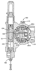
A currently preferred embodiment of regulator flow measurement and
diagnostic apparatus is illustrated in FIG. 3, generally designated by
reference numeral
100. As shown in FIG. 3, the apparatus 100 includes a magnet housing 1 O l
having a first
end 102 adapted for connection to the diaphragm housing 14 of the regulator.
The
magnet housing 101 defines an inner surface 250, and encloses a travel
indicator 103
(FIG. 4) which is adapted for connection to the diaphragm 26 (FIG. 1 ) in the
regulator.
A magnet assembly 252 is disposed inside the magnet housing 101 for
CA 02435179 2003-07-16
WO 02/057861 PCT/USO1/48430
- 10-
providing a magnetic flux pattern. As best shown in FIGS. 4, 8, and 9, the
magnet
assembly 252 comprises a single bar magnet 254, preferably having a
cylindrical shape,
having a north pole 256 and a south pole 258. The magnet 254 is preferably a
permanent
magnet constructed ofAlnico V magnetic material that serves as a constant
magnetic flux
source. The magnet 254 is pr eferably packaged in a shuttle 260 having a
central bore 261
sized to receive the magnet 254. The shuttle 260 is constructed of a non-
magnetic
material, preferably aluminum or ceramic, and has an outer surface 263 sized
to be
slidably received by the inner surface 250 of the magnet housing 101. The
shuttle 260
may conveniently be a two-piece or clam-shell housing held together by a
suitable
fastener.
In the embodiment illustrated at FIG. 8, flux-shaping pole pieces 262, 264
are threadably fastened inside opposite end recesses 265 of the shuttle 260 to
sculpt the
magnetic flux generated by the magnet 254. Each of the pole pieces 262, 264
includes
a face 266 arranged to confront and abut opposite end pole faces 268 of the
magnet 254,
as best shown in FIG. 9. The pole pieces 262, 264, which are composed of a
suitable
magnetic material such as G 14100 cold-rolled steel, are preferably generally
cylindrical
in shape having opposite parallel circular surfaces 266, 272 and a cylindrical
surface 274
arranged to confront a longitudinal space containing a magnetic field sensor
276. A
frusto-conical surface 278 forms a transition between the circular surfaces
266 and the
cylindrical surface 274, and also confronts the longitudinal space.
In a preferred embodiment of the invention, the magnet 254 has a diameter
of about 0.375 inches and a length of about 2.5 inches. The diameter of the
circular faces
266 on pole pieces 262, 264 is about 0.375 inches and cylindrical surface 274
has a
diameter of about 0.8125 inches and a length along axis 280 of about 0.125
inches.
Frusto-conical surface 278 is arranged at an angle of about 20° to
surface 266. The
magnetic field sensor 276 is mounted to the valve housing or other stationary
obj ect and
is oriented along axis 282 parallel to axis 280. The shuttle 260 is arranged
to move along
axis 280. For a sensor arrangement as described, axis 282 is 0.625 inches from
axis 280.
It is important to the present invention that the cylindrical surface 274 is
parallel to and coaxial with axis 280 and a surface 286 of the magnet 254.
This
relationship is accomplished by the circular face 266 on the pole piece
confronting the
CA 02435179 2003-07-16
WO 02/057861 PCT/USO1/48430
-11-
circular pole face 268 of the magnet and the coaxial relationship of surfaces
266 and 274.
As a result of this condition, the magnetic field flux is symmetrically
configured about
the axis 280 of the magnet. As shown in FIG. 9, the length of the magnet 254
in a
direction along axis 280 and the configuration of the cylindrical surface 274
and the
frusto-conical surface 278 sculpt the fringing magnetic flux pattern in a
region adjacent
the magnet 254 so that the magnetic flux varies 1 inearly along the axis 282
parallel to axis
280. Therefore, magnetic displacement sensor 276 senses a flux density that
varies
linearly along the length of travel of the sensor. Because the magnetic flux
is uniform
about the periphery of the magnet, the sensor is insensitive to relative
rotation of the
elements about axis 280. Hence, the sensor is insensitive to rotation of the
magnet 254
about its axis 280.
The flux density increases uniformly along longitudinal line 282 parallel
to the magnet from the midpoint 288 of the assembly toward the poles, to a
maximum
flux density directly opposite pole faces 274. Because poles 256, 2S8 are
oppositely
oriented, the flux directions through sensor 276 are in opposite directions at
the regions
along line 282 on each side of the midpoint 288. Hence, the flux density
varies along line
282 from a maximum in one direction adjacent a pole face 274 adjacent one pole
256,
through zero at midpoint 288, to a maximum in the opposite direction adjacent
the pole
face 274 adjacent the other pole 258. At midpoint 288 centered between the
pole pieces,
the magnetic flux density is at a null (zero). The sensor is calibrated by
placing the
sensor 276 at the midpoint 288 where magnetic field strength is zero and
calibrating the
sensor.
In use, the shuttle 260 reciprocates along line 280, causing the linearly-
varying flux pattern of magnet 254 to pass along the sensor 276 to produce a
voltage
proportional to the relative position of the magnet 254 in relation to the
magnet assembly
252. By sculpting the fringing flux, pole pieces 262, 264 linearize the flux
over the
length of the magnet. Thus, pole pieces 262, 264 dramatically increase the
useful range
and accuracy of the voltage readings produced by the magnetic field sensor
276.
A pair of centering rings 290 is provided for further improving accuracy
of the sensor voltage readings by ensuring that the magnet assembly 252 is
centered in
the magnet housing 101. As best shown at FIG. 8, a pair of grooves 292 are
formed in
CA 02435179 2003-07-16
WO 02/057861 PCT/USO1/48430
-12-
the shuttle outside surface 263. The centering rings 290 are inserted into the
grooves
292, each having an outwardly biased outer wall 294. The outer wall 294
engages the
inner surface 250 of the magnet housing 101 thereby to center the magnet
assembly 252
inside tile magnet housing 101. In the embodiment illustrated at FIG. 8, each
centering
ring 290 comprises an inner O-ring 296 formed of a relatively resilient
material, such as
robber, and an outer ring 298 formed of a relatively rigid material having a
relatively low
coefficient of friction, such as plastic, to allow the outer rings 298 to
slide along the
magnet housing inner surface 250. It will be appreciated, however, that other
materials
may be used to bias the outer wall 294 outwardly.. For example, in the
embodiment
illustrated at FIG. 10, each centering ring 290 has an inner member comprising
an
annular spring 299, and an outer member comprising a plastic outer ring 298.
The
annular spring 299 may be formed of metal, such as steel.
In an alternative embodiment illustrated at FIG. 1 l, a pair of centering
rings 300 are provided which generate an inward force for centering a magnet
302 in the
magnet housing 1.01. Pole pieces 304, 306 axe positioned at opposite ends of
the magnet
302 to sculpt the magnet flux. A shuttle 308 is provided for packaging the
magnet 302
and pole pieces 304, 306 in an integral magnet assembly 310. Grooves 312 are
formed
in the inner surface 250 of the magnet housing 1 O1 and are sized to receive
outer portions
of the centering rings 300. Each centering ring 300 includes an inner wall 314
that is
biased inwardly to engage an outer surface 316 of the shuttle 308. In the
embodiment of
FIG. 11, each centering ring 300 includes an inner rigid member, such as inner
plastic
ring 318, defining the inner wall 314. Each centering ring 300 further
includes an outer
resilient member, such as outer annular spring 320, which pushes inwardly on
the inner
plastic ring 318 to bias the inner wall 314. As a result, the magnet 302 is
centered inside
the magnet housing 101.
While each of the illustrated embodiments shows the use of two centering
rings, it will be appreciated that a single centering ring may be used,
depending on the
relative lengths of the biased wall and the magnet. Furthermore, more than two
centering
rings may be provided without departing from the spirit and scope of the
present
invention.
An electrical housing 106 is attached to the magnet housing 101 and has
CA 02435179 2003-07-16
WO 02/057861 PCT/USO1/48430
- 13-
a first pressure port 107, a second pressure port 108, an auxiliary pressure
port 109, and
an auxiliary port 110 (FIG. 3). A first pressure sensor assembly 111 is
inserted inside the
first pressure port 107, and a tube (not shown) connects the assembly I 1 I to
the upstream
section of the flow passage. A second pressure sensor assembly 1 I4 is
inserted into the
second pressure port 108, and a tube (not shown) connects the second assembly
114 to
the downstream section of the flow passage. A third pressure sensor assembly
115 may
be inserted into the auxiliary pressure port 109 for measuring at a third
pressure point.
The third pressure sensor 115 may be used to measure pressure at a variety of
locations,
including in the flow passage or in the regulator to infer plug travel, as
described in
greater detail above with regard to the previous embodiment. In a preferred
embodiment,
a fourth pressure port 117 is provided for measuring atmospheric pressure. The
auxiliary
port 110 is provided for receiving discrete or analog input from another
device, such as
the temperature transmitter 48 illustrated in FIG. 1. In addition, an Il0 port
112 is
provided for connection to an outside device, as described in greater detail
below.
A plurality of circuit boards 120a-a are disposed inside the housing for
controlling various operations of the apparatus 100 (FIG. 5). In the
illustrated
embodiment, a first (or main) circuit board 120a may include an interface for
the first,
second, third pressure sensors, and atmospheric pressure sensors, and a
connection for
the magnetic field sensor 276. A second (or communication) circuit board 120b
provides
an interface for communication with outside devices. The second circuit board
120b may
include connection for wired transmission, such as a modem card, an RF232
communication driver, and a CDPD modem. In addition or alternatively, a
transceiver
may be provided for wireless communication. A third (or main) circuit board
120c
preferably includes a processor, a memory, a real-time clock, and
communication drivers
for two communication channels. The processor may include, among other things,
one
or more of the algorithms noted above for calculating flow rate, while the
memory may
store selected parameters, such as the high and low pressures for each day. An
optional
fourth circuit board 120d provides an interface for the auxiliary
communication device
55. A fifth (or termination) board 120e is also provided having a power supply
regulator,
field termination (for connection to I/O devices), a back-up power supply, and
connections into which the other boards 120a-d may plug into. While fve
circuit
CA 02435179 2003-07-16
WO 02/057861 PCT/USO1/48430
- 14-
boards 120a-a are shown in the i Ilustrated embodiment, it will be appreciated
that a single
circuit board, less than five circuit boards, or more than five circuit boards
may be used
without departing from the scope of the invention.
It will be appreciated, therefore, that communication between the
apparatus 100 and an outside device may be by RF modem, ethernet or other
known
communication like. The processor al lows the outside devices to enter
information such
as desired pressure set points and alarm conditions into the apparatus 100,
and retrieve
data stored in the memory. The data retrieved may include the alarm log and
stored
operational parameters. For instance, the retrieved information may include a
history of
upstream and downstream pressures stored periodically in memory, so that the
apparatus
100 provides the function of a pressure recorder.
In accordance with certain aspects of the present invention, the processor
includes a routine for generating alan~a signals. A first portion of the
routine compares
measured parameters (i.e.; the upstream pressure, downstream pressure, and
travel
position) to certain user-specified limits, as schematically illustrated in
FIG. 5. In
addition, one or more logic sub-routines may be run which compares at least
two of the
measured parameters and generates an alarm signal based on a specific logical
operation,
examples of which are schematically shown in FIGS. 6 and 7A-7D.
Turning first to the level alarms, a check is initiated 150 to determine
whether any level limits have been entered by the user. The pressure, travel,
flow, and
battery values are first compared to user entered high-high limits 151. If any
of the
values exceeds the high-high limits, the date and time are read 152 and a
corresponding
high-high alarm is logged 153. Next the measured values are compared to user
entered
high limits 154. If any of the values exceeds the high limits, the date and
time are read
155 and a corresponding high alarm is logged 156. The values are then compared
to user
entered low limits 157. If any of the values is lower than a user entered low
limit, the
date and time are read 158 and a corresponding low alarm is logged 159.
Finally, the
values are compared to user entered low-low limits 160. If any of the values
is Lower
than a low-low limit, the date and time are read 161 and a corresponding low-
low alarm
is logged 162.
Additional limit alarms may be set based on the calculated flow rate F.
CA 02435179 2003-07-16
WO 02/057861 PCT/USO1/48430
-15-
For example, a user may enter limits for instantaneous and accumulated flow.
When the
calculated flow rate F exceeds either of these limits, an alarm is triggered.
A further
alarm may be provided based on stem travel. The user may enter a limit for
accumulated
stem travel distance and trigger a maintenance alarm when accumulated stem
travel
exceeds the limit.
After checking the user-entered limit alarms, one or more logic sub-
routines may be run to determine if any logical alarm conditions exist. In the
preferred
embodiment, each of the logic sub-routines is combined into a single,
integrated logic
sub-routine as generally illustrated in FIG. 6. As shown in FIG. 6, the sub-
routine begins
by collecting all the pressure and travel data, in calculating the flow 165
through the
pressure regulator. Each of the measured parameters is then compared to both
the other
measured parameters and any user-specified set points. The logical alarms are
monitored
for upstream pressure 166, downstream pressure 167, auxiliary pressures I 68,
stem travel
169, and flow rate I70. Additional logical alarms may also be provided for
feedback
from the third pressure sensor assembly and auxiliary device connected to the
1/O
connection 112. After obtaining the relative values of each of the parameters,
the logical
alarms are then checked, as described in greater detail below.
A preferred sequence of operations for determining logical alarms based
on upstream pressure (step 166) are schematically shown in FIG. 7A. First, the
sub-
routine checks for an entered value relating to upstream pressure 172. If a
value is
entered relating to upstream pressure, the sub-routine determines whether the
measured
upstream pressure must be greater than 173, less than 174, or equal to 175 the
user-
entered value. For each relative comparison (i.e., steps 173, 174 and 175), a
series of
sub-steps are performed as illustrated in FIGS. 7B-7D.
If an alarm requires the upstream pressure to be greater than a certain
value, the sub-routine first checks for a specific upstream pressure value
entered by the
user 176 (FIG. 7B). If the user has entered a value for upstream pressure, the
measured
upstream pressure is compared to that entered value 177. If the measured value
is greater
than the entered value, the upstream pressure greater than flag is set 178. If
no'specific
user-entered value is used, the sub-routine checks to see if downstream
pressure is to be
compared to the upstxeam pressure I 79. If so, the sub-routine determines if
the upstream
CA 02435179 2003-07-16
WO 02/057861 PCT/USO1/48430
- 1G -
pressure is greater than the downstream pressure 180. if so, the upstream
pressure greater
than downstream pressure flag is set 181. Ifdownstream pressure is not used as
a logical
alarm, the sub-routine next checks for a logical alarm value based on
auxiliary pressure
182. !f auxiliary pressure is used as a logical alarm, the sub-routine checks
whether
upstream pressure is greater than the downstream pressure 183. If so,
the.upstream
pressure greater than auxiliary pressure flag is set 184.
As illustrated in FIGS. 7C and 7D, the sub-routine perfornis similar steps
to detennine if upstream pressure is less than or~equal to a logical alarn~
value 185-202.
Furthermore, operations identical to those shown in FIGS. 7B-7D are performed
for the
downstream and auxiliary pressures to determine whether they are greater than,
less than,
or equal to specified logic alarm values. Since these operations are
identical, separate
flow chac-ts illustrating these steps are not provided.
Turning to logic alarms based on travel 169 (FIG. 7A), a logic sequence
flow chart is illustrated at FIG. 7E. Accordingly, the sub-routine first
checks whether a
travel position logic value has not been entered 203. If a traveled position
logic value has
been entered, the sub-routine determines whether the measured value must be
greater
than the logic value 204. If the logic operator is a greater than Limit, the
sub-routine
determines whether the measured traveled position is greater than the entered
value 205.
If so, the travel greater than flag is set 206. If no "greater than" limit is
used for travel,
the sub-routine then checks for a "less than" limit 207. If a "less than"
limit is detected,
the sub-routine determines if the measured travel is less than the entered
value 208. If
so, the travel less than flag is set 209. If a "less than" value is not used,
the sub-routine
checks for an "equal to" operator limit 210. If an "equal to" limit is used,
the sub-routine
determines whether the measured travel equals the entered value 211. If so,
the travel
equal to flag is set 212. A similar sequence of steps may be used to determine
if the
calculated flow rate is greater than, less than, or equal to a logic flow
alarm value, as
called for at step 170 of FIG. 6.
Based on the logic flags which may be set, certain logic alarms may be
triggered based on a comparison of two of the measured parameters. For
example, a shut
off problem alarm may be set to trigger when travel position equals zero and
downstream
pressure is increasing (present downstream pressure is greater than
immediately
CA 02435179 2003-07-16
WO 02/057861 PCT/USO1/48430
_17_
preceding measured downstream pressure). When the appropriate operational
conditions
exist to set the corresponding logic flags, the shut off problem alarm is
triggered, which
may indicate that fluid is leaking through the pressure regulator possibly due
to damage
to the throttling element. Another logic alarm may be generated when the
travel value
is greater than zero and the downstream pressure signal is decreasing, which
may indicate
a broken stem. Yet another logic alarm maybe generated when the travel value
is greater
than zero and the upstream pressure signal is increasing, which may also
indicate a
broken stem or other problem with the regulator. A further logic alarm may be
triggered
when the travel signal is greater than zero and the downstream pressure signal
is greater
than a user entered downstream pressure limit, which may indicate a problem
with the
pilot which controls the regulator. Other logic alarms may be entered which
take into
account the various measured and calculated values, so that other potential
problems with
the regulator may be immediately indicated.
The memory associated with the processor preferably includes an alarm
log which tracks the date, time, and type of alarm. The alarm log is
accessible by an
outside communication device to allow an alarm history to be retrieved.
Furthermore,
the processor preferably includes a report by exception (RBX) circuit which
automatically communicates any alarm conditions to a remotely located host
computer.
Accordingly, potential problems in the pipeline are quickly reported, and the
particular
component or damaged area is identified.
While a combined regulator flow measurement and diagnostic apparatus
has been illustrated and described, it will be appreciated that a separate
regulator flow
measurement apparatus or a separate regulator diagnostic apparatus may be
provided in
accordance with the present invention.
The foregoing detailed description has been given for clearness of
understanding only, and no unnecessary limitations should be understood
therefrom, as
modifications will be obvious to those skilled in the art.