Note: Descriptions are shown in the official language in which they were submitted.
CA 02435421 2003-07-17
- 1 -
METHOD FOR M19-KING AN ARTICLE COMPRISING A SHEET AND AT
LEAST AN ELEMENT DIRECTLY MOUNTED THEREON
The subject of the present invention is especially a
process for manufacturing an article comprising a sheet
and a security element introduced into the sheet.
The invention relates more particularly, but not
exclusively, to the incorporation of an element, such
as an electronic chip, into an article, for example a
security document.
Many examples of structures that include an electronic
chip may be mentioned.
International application WO 99/54842 discloses a paper
banknote provided with a security thread that includes
an electronic chip made of a semiconducting organic
polymer.
German patent application DE 198 33 746 discloses a
traveler's check obtained by placing a band of polymer
material that includes an electronic chip on a first
layer of paper and attaching to this first layer a
second layer of paper, so that the band of polymer is
sandwiched between the two layers.
German patent application DE 196 01 358 discloses a
paper article that includes, embedded in its thickness,
a micromodule consisting of an integrated circuit and a
metal film.
German patent application DE 196 30 648 discloses a
banknote that includes an interrupted security band and
an electronic chip placed between two portions of this
band.
CA 02435421 2003-07-17
- la -
Also known, from international application WO 00/26856,
is a label that includes an electronic chip housed in a
CA 02435421 2006-10-10
-2-
hole in a flexible substrate. The chip is held in this
hole by means of an epoxy resin.
The aim of the present invention is in particular to
provide a novel process for manufacturing an article
comprising a sheet and at least one attached element,
such as an electronic chip for example.
According to the present invention, there is provided a process for
manufacturing an article comprising a sheet and at least one element having a
certain thickness, comprising the following steps:
- providing a sheet with at least one cavity open on one side;
- placing said element in this cavity by applying, to said side, a structure
comprising at least one layer carrying the element, said structure being
positioned with respect to the sheet so that the element is at lea'st partly
housed
in the cavity,
wherein the sheet and the element are joined together by transfer by removing
one or more layers of the structure.
The structure, apart from the fact that it can cover
the cavity, may define a visible surface of the
article, this surface possibly constituting a security
device for example.
The layer carrying the element may be made of plastic
or metal. It may be formed from a thin plastic film or
a metal film or coating, for example.
The layer carrying the element may also provide for the
application of a film-forming composition, especially a
magnetic or iridescent film-forming composition.
The layer carrying the element may also be based on
fibrous material.
CA 02435421 2003-07-17
- 3 -
In a preferred method of implementing the invention,
the sheet and the element are joined together by hot or
cold transfer. For example, the element carried by the
structure may be transferred onto the sheet in the
following manner:
- the running sheet is pressed against a die
carried by a rotating roll, the die being moved in
synchronism with the sheet;
- the structure is brought between said die and
the sheet so that the structure comes into contact with
the sheet and the element is transferred into the
cavity of the sheet; and
- optionally, after the element has been
transferred to the sheet, one or more layers of the
structure are removed.
For example, after transfer, it is possible for only
the element and an adhesive layer of the structure to
be retained, it being possible for said adhesive layer
to help to fasten the element in the cavity of the
sheet.
In one particular method of implementation, the
structure is brought up against the sheet in a
direction generally transverse to the direction in
which the sheet runs.
In another example of a method of implementing the
invention, the sheet and the structure are joined
together by adhesive bonding.
A registration means may be used in order to allow
precise placing of the element in the cavity of the
sheet.
Such a registration means may comprise printing or a
watermark on the sheet.
CA 02435421 2003-07-17
- 4 -
When the sheet and the structure have been joined
together by adhesive bonding, the layer of the
structure carrying the element may be based on a
material other than a fibrous material, for example a
plastic, the structure possibly containing no fibrous
material at all.
When the sheet and the structure are joined together by
adhesive bonding and the layer of the structure
carrying the element is based on a fibrous material,
the article may consist, for example, of an article
other than a passport, an identity card, a family
record book or a savings passbook.
In one example of a method of implementing the
invention, the depth of the cavity is greater than or
equal to the thickness of the element.
Thus, there is no increase in thickness of the article
at the point where the element is. The element, for
example an electronic chip, may thus be made difficult
to detect visually and by feel.
In addition, when the depth of the cavity is chosen so
that the element is housed in the cavity without
projecting therefrom, the element is protected from any
pressure exerted during the manufacture of the article
or during its use.
The cavity may or may not be a through-cavity.
The sheet may be made in a material chosen so as to
have resilience properties sufficient to protect the
element housed in the cavity from mechanical stresses
such as shocks or pressure exerted by a printing
machine.
The structure may or may not cover all of one side of
the sheet. The structure may, for example, be in the
CA 02435421 2003-07-17
- 5 -
form of a band not covering all of one side of the
sheet. This band may extend without a break between two
opposed edges of the article. The structure may also
not extend without a break between opposed edges of the
article and may thus form a patch.
The article may include, in line with the element, a
relief that can be detected by feel or an area of
hardness or softness that can be detected by feel, so
as, for example, to allow an unsighted person to
recognize the article.
The structure may be transparent or opaque, partially
metalized or have a layer of metal completely covering
one of its sides.
The structure may also include a holographic and/or
diffractive element. The structure may also include a
magnetic, metallic or crystalline coating or else
iridescent, thermochromic and/or piezochromic pigments.
In one particular embodiment, the structure includes
liquid crystals.
The structure may also receive at least one printing
element, for example a varnish or ink printing element.
In one particular embodiment, the structure includes at
least one reflecting surface that may or may not be
continuous.
The layer of the structure carrying the element may be
fastened to a carrier layer, before the element is
transferred to the sheet. The carrier layer may be
removed after the layer carrying the element has been
joined to the sheet. The layer carrying the element may
thus be transferred onto the sheet. The layer carrying
the element may be formed by a film, for example.
CA 02435421 2003-07-17
= - 6 -
The carrier layer may optionally carry a number of film
or fibrous portions placed so that, after their
transfer to the sheet, these portions are spaced apart
on the surface of the sheet. The article may include
one or more of said portions. Each portion may carry
one or more elements, these being identical or
otherwise. Said portions may be separated from one
another on the carrier layer, for example being
uniformly spaced apart. Each portion may have a
polygonal, oval, circular or other outline, and form a
patch for example.
The structure may or may not be of the multilayer type.
For example, it is possible for the sheet to be brought
into contact with a composite structure, also called a
foil, initially comprising the following layers:
- a carrier layer, for example made of polyester;
- a release layer, for example made of wax;
- optionally, a layer of varnish containing a
resin and optionally a dye;
- a layer of metal, for example aluminum, of
plastic or of fibrous material, or a layer deriving
from the application of a film-forming composition,
especially a magnetic or iridescent film-forming
composition; and
- an adhesive layer.
Such an adhesive layer may be used to fasten, for
example, the element to the sheet.
The sheet may receive beforehand an undercoat or
adhesion primer, for improving the fastening of the
element to the sheet and/or the surface characteristics
of the sheet.
The structure may be joined to the sheet in various
ways, for example by hot pressing.
CA 02435421 2003-07-17
- 7 -
The nature of the metal layer and its surface
appearance may be chosen so as to reflect light through
the layer of colored varnish, as the case may be.
The structure may essentially be formed by a film,
especially a metal film or a plastic film, for example,
and the entire structure may be left to remain on the
sheet. There may be just one such film.
The structure may also be formed by a layer coming from
the application of a film-forming composition.
The structure may be formed by just one film or just
one layer, made of fibrous material or otherwise.
In one particular embodiment of the invention, the
element includes an electronic chip, for example
allowing contactless data transmission. This chip may
be connected to an antenna comprising at least one
turn. The antenna may be carried by a film and extend
around the chip on the film. As a variant, the antenna
may be placed on the chip itself. The chip may be based
on silicon.
The element may be formed by an element other than an
electronic chip.
In one particular embodiment, the element is capable of
retransmitting a signal when the article is placed in a
predetermined electromagnetic or light field.
The element may include magnetic, metallic or plastic
particles having a hardness or softness that can be
detected by feel.
The element may also include crystals or biomarkers.
In one embodiment of the invention, the sheet includes
at least one fibrous layer, or else just one fibrous
CA 02435421 2003-07-17
- $ -
layer. The sheet may for example include cellulose
fibers and/or other natural, artificial or synthetic
fibers. The sheet may also include, for example, at
least one layer of plastic.
In one particular method of implementing the invention
the cavity intended to house the element is cut out by
means of a laser. As a variant, the cavity may be cut
out by mechanical abrasion.
As another variant, the cavity is produced during
formation of the sheet on the paper machine and the
sheet may in particular be produced in the following
manner:
- a first ply of paper is formed on contact with a
surface immersed in a dispersion of fibrous material,
this first ply having an area of reduced thickness, or
even a hole, in order to form said cavity;
- the first ply of paper is joined to a second ply
of paper.
The element may be placed in the cavity on a hot- or
cold-transfer machine, before the article is dried on a
paper machine.
As a variant, the element is transferred to the sheet
on a transfer machine integrated into a printing
machine.
The article obtained may have a number of cavities,
each receiving one element. These cavities may receive
different elements and/or elements having complementary
functions.
The subject of the invention is also an article
obtained by implementing the process described above.
The article may constitute, for example, a banknote, a
security paper, a gift voucher, a coupon, a value
CA 02435421 2006-10-10
-9-
document, a mark or product protection label or a
traceability label, this list not being exhaustive.
According to the present invention, there is also provided an article
comprising a
sheet with at least one fibrous layer, having at least one cavity at least
partly
housing an element of a certain thickness, this cavity being covered by a
structure comprising at least one layer of plastic, metal or fibrous material,
or by
a layer deriving from the application of a film-forming composition, wherein
the
at least one layer of the structure includes a plurality of film or fibrous
portions
spaced apart on the surface of the sheet.
Especially when the article consists of an article
other than a passport, an identity card, a family
record book or savings passbook, the cavity of the
sheet may be covered, for example, by a layer of
fibrous material.
When the cavity is a through-cavity, the sheet may be
covered on both sides by a layer of fibrous material.
In other words, the sheet is sandwiched between two
fibrous layers.
A clearer understanding of the invention may be gained
on reading the following detailed description of
nonlimiting embodiments and on examining the appended
drawing in which:
- figure 1 shows schematically and partially, in
cross section, an article according to a first
embodiment of the invention;
- figure 2 shows schematically and partially, in
cross section, an article according to a second
embodiment of the invention, including a relief that
can be detected by feel;
- figure 3 shows schematically and partially, in
cross section, an article according to a third
ernbodiment of the invention, also including a relief
that can be detected by feel;
CA 02435421 2003-07-17
- 10 -
- figure 4 is a schematic and partial cross
section of a structure that can be used;
- figure 5 shows schematically and partially a
banknote according to the invention;
- figures 6 and 7 show schematically and partially
gift vouchers according to two embodiments of the
invention;
- figure 8 shows, schematically, an example of a
plant for producing a sheet with cavities that open on
one side;
- figures 9 and 10 show partially and
schematically, in cross section, two embodiments of a
sheet that can be obtained with the plant of figure 8;
- figure 11 illustrates schematically the
lamination of a sheet and a structure;
- figure 12 illustrates schematically, in cross
section, the transfer of an element to a sheet; and
- figure 13 shows schematically and partially a
detail of figure 12.
Throughout the description, including the claims, the
expressions "comprising one" and "including one" must
be understood as meaning "comprising at least one",
unless otherwise specified.
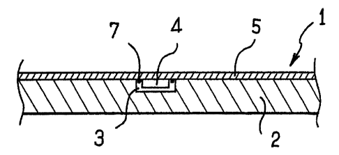
Figure 1 shows an example of an article 1 according to
the invention, comprising a sheet 2 having, on one
side, a non-through-cavity 3 for receiving an element,
such as an electronic chip 4, fastened to a structure 5
formed by a film, for example a polyester film.
In the example illustrated, the sheet 2 is based on
fibers, for example cellulose fibers, and may also
contain, optionally, synthetic or artificial fibers. As
a variant, the sheet 2 may be based essentially on a
material other than a fibrous material.
In the example shown in figure 1, the depth of the
cavity 3 is greater than the thickness of the chip 4 so
CA 02435421 2003-07-17
- 11 -
that the article 1 has no additional thickness at the
point in line with the chip 4.
As a variant, the depth of the cavity 3 is less than
the thickness of the chip 4, so as to create a relief
on the surface of the article 1, as may be seen in
figure 2. This relief may be detected by feel, so as to
allow an unsighted person to recognize the article 1.
The chip 4 may be of the passive type, allowing
contactless data transmission, and may be connected to
an antenna 7 comprising at least one turn. This antenna
may be produced, for example, directly on the film 5,
around the chip 4, allowing detection in the vicinity
or neighborhood, for example detection with a range of
between 1 and 70 cm.
As a variant, the antenna may be produced on the chip
itself, when short-range detection is sufficient, for
example with a range of greater than 1 mm but less than
about 1 cm.
The chip 4 is, for example, based on silicon and may
have a thickness of about 200 m for example.
The cavity 3 may receive an element other than an
electronic chip 4.
Figure 3 shows an article 1' that differs from the
article 1 described above in the fact that the cavity 3
receives particles 6. These may, for example, be
magnetic or nonmagnetic, metallic or plastic.
In the example illustrated, the particles 6 are in an
amount sufficient to create on the surface of the
article 1' a relief detectable by feel.
The structure 5 may have locally, in line with the
cavity 3, a softness or hardness detectable by feel,
CA 02435421 2003-07-17
- 12 -
thus allowing an unsighted person to recognize the
article.
The element placed in the cavity 3 may also consist of
an object of predetermined shape, merely having the
function of creating a relief that can be detected by
feel.
The structure may, for example, consist of a single
polyester film, as illustrated above. It would not be
outside the scope of the present invention to use a
different structure, especially a multilayer structure.
As an example, figure 4 shows a composite structure 5'
comprising:
- a carrier layer 10 made of polyester;
- a release layer 11, for example made of wax;
- a layer of varnish 12 containing a resin and
optionally a dye;
- a metal layer 13, for example made of aluminum;
- an adhesive layer 14 for fastening the element 4
to the fibrous layer 2. The adhesive layer 14 may be
based on a hot-melt resin.
In the example described, the carrier layer 10 has a
thickness of about 12 m and the combined thickness of
the layers 11 to 14 is about 2 to 3 m.
The layers 12, 13 and 14 form a film 5" to be
transferred to the sheet 2.
The structure 5' is also called a foil and it allows
the film 5" to be joined to the sheet 2, for example by
hot pressing, during which operation the release layer
11 melts and allows the carrier layer 10 to be
separated from the other layers. The heat provided
during this operation also activates the adhesive layer
14, so as to thermally bond the film 5" to the sheet 2.
CA 02435421 2003-07-17
- 13 -
The metal layer 13, for example made of aluminum, may
have a surface appearance allowing light to be
reflected through the layer of colored varnish 12, thus
creating a color effect on the surface of the article.
The layer 12 may have a hologram formed by a
diffraction grating. The latter may be produced by
means of a die of a transfer machine for transferring
the film 5" to the sheet 2. As a variant, the hologram
may be produced before the layer 12 is joined to the
other layers.
The metal layer 13 may be replaced with a plastic
layer.
The film 5 or 5" may or may not entirely cover one side
of the article.
The film 5 or 5" may extend with or without a break
between two opposed edges of the article.
The film 5 or 5" may form a patch on the article.
To illustrate a number of these options, a few examples
of articles that can be obtained by implementing the
invention will now be described.
Figure 5 shows a bank note 20 comprising a film 5 or 5"
and a sheet 2.
The film 5 or 5" in this example consists of a band
extending between two opposed edges of the banknote 20.
A number of individual reflecting surfaces 21, each
having the shape of a parallelogram, are produced on
the visible side of this band 5 or 5".
As disclosed in European patent EP 0 522 217, these
reflecting surfaces.21 may be produced by transferring
a continuous reflecting thin film 5 or 5" onto the
= CA 02435421 2003-07-17
- 14 -
sheet 2, and then by printing opaque areas 22 on this
film. This printing may be carried out, for example, by
means of an ink. The opaque areas 22 may as a variant
be obtained by locally dissolving the film 5 or 5". The
banknote 20 may have one or more elements housed in
cavities beneath the film 5 or 5".
Figures 6 and 7 show two gift vouchers 25 and 25' that
include a sheet on which a bar code 26 has been
printed.
The voucher 25 includes a film 27 that is small
compared with the sheet, this film 27 having a
structure allowing a holographic image 28 to be
created. This film 27 covers a cavity of the fibrous
layer housing an electronic chip (not shown). The film
27 constitutes a patch.
The voucher 25' has a film 30, for example a
transparent film, entirely covering the underlying
sheet. The chip 29 is housed in a cavity of the fibrous
layer and may be seen through the film 30 when the
latter is transparent.
The cavity receiving the element may be produced in
many ways.
As an example of one possible way among others of
producing a cavity, a process for producing a sheet
comprising at least one cavity open on one side will
now describe with reference to figure 8.
This figure shows, partially and schematically, two
paper machines 35 and 36 called cylinder mold machines.
The first machine 35 has a tank 37 containing a
suspension of fibers, for example cellulose fibers, in
which suspension is partly immersed a rotating wire
cylinder 38 defining.a surface 39 in contact with which
r CA 02435421 2003-07-17
- 15 -
a ply of paper 40 is continuously formed and taken up
by a take-up felt 42. The surface 39 is embossed so as
to create, in the first ply 40, areas of reduced
thickness 45, as illustrated in figure 9, or holes 46,
as illustrated in figure 10, these areas being intended
to form cavities in the sheet.
The second machine 36 has, like the machine 35, a tank
37 and a rotating wire cylinder 44 defining a surface
47 in contact with which a second ply of paper 41 is
formed. The plies of paper 40 and 41 are joined
together, for example by passing them between the
cylinder mold 44 and a rotating roll 48.
An example of such a plant is described in European
patent EP 0 687 324.
Thereafter, the sheet may be cut to the dimensions of
the article to be produced.
The cavity may be produced by yet other means, for
example using a laser or by mechanical abrasion.
The structure and the sheet may be joined together in
many ways without departing from the scope of the
invention.
For example, the structure and the sheet may be joined
together by lamination, as illustrated in figure 11, by
passing them between two rotating rolls 50 and 51. In
this figure, the film 5 is brought beforehand into
contact with a size applicator 53. The film 5 and the
sheet 2 may then be positioned one with respect to the
other by registration, so that an element carried by
the film 5 is housed in a cavity of the sheet. In the
example in question, the film 5 remains in place on the
sheet 2.
CA 02435421 2003-07-17
- 16 -
In the case of the composite structure 5', the film 12,
13, 14 may be transferred, for example hot, to the
sheet 2, as illustrated in figures 12 and 13. In such a
transfer process, the sheet 2 and the structure 5' may
be entrained with the carrier layer 10, 11 by moving
them in the same direction by means of a machine
comprising a first rotating roll 55 carrying dies 56
and a second rotating roll 57. The film 12, 13, 14 and
the sheet 2 may be joined together by passing them
between the rolls 55 and 57. It may be seen in figure
13 that, after passing between the rotating rolls 54
and 57, the carrier layer 10 and the release layer 11
are separated from the other layers 12, 13 and 14,
transferred to the sheet 2.
The hot-transfer machine shown in figures 12 and 13
may, without restriction, operate according to the
principles of the "Foil-Jet" machine sold by Steuer
GmbH and described, for example, in patent application
DE-19625064.
The film 12, 13, 14 may also be taken between a die 56
and the sheet 2 in a direction generally transverse to
the movement of the sheet, as described in European
patent EP 0 473 635.
Of course, the invention is not limited to the
embodiments that have just been described.
The cavity or cavities in the sheet may or may not be
through-cavities. Each cavity may be closed on one side
only by a film, or on both sides by two films. Each
through-cavity may also be closed on one side by a film
and on the other side by a fibrous layer. Especially
when the element is placed in the cavity of the film by
transfer, the layer of the structure carrying the
element may be based on a fibrous material.