Language selection

Search

Patent 2435654 Summary

Third-party information liability

Some of the information on this Web page has been provided by external sources. The Government of Canada is not responsible for the accuracy, reliability or currency of the information supplied by external sources. Users wishing to rely upon this information should consult directly with the source of the information. Content provided by external sources is not subject to official languages, privacy and accessibility requirements.

Claims and Abstract availability

Any discrepancies in the text and image of the Claims and Abstract are due to differing posting times. Text of the Claims and Abstract are posted:

  • At the time the application is open to public inspection;
  • At the time of issue of the patent (grant).
(12) Patent Application: (11) CA 2435654
(54) English Title: ELECTRONIC FLUID PUMP WITH ENCAPSULATED STATOR ASSEMBLY
(54) French Title: POMPE ELECTRONIQUE MUNIE D'UN ENSEMBLE STATOR ENCAPSULE
Status: Dead
Bibliographic Data
(51) International Patent Classification (IPC):
  • F04B 17/00 (2006.01)
  • F04D 13/06 (2006.01)
  • F04D 29/58 (2006.01)
(72) Inventors :
  • BADER, MARK (United States of America)
  • LASECKI, MICHAEL P. (United States of America)
  • SHIVERSKI, STEVEN (United States of America)
  • DEGRAVE, KENNETH A. (United States of America)
  • CARLSON, JEREMY S. (United States of America)
(73) Owners :
  • EMP ADVANCED DEVELOPMENT, LLC (United States of America)
(71) Applicants :
  • ENGINEERED MACHINED PRODUCTS, INC. (United States of America)
(74) Agent: SMART & BIGGAR
(74) Associate agent:
(45) Issued:
(86) PCT Filing Date: 2002-01-30
(87) Open to Public Inspection: 2002-08-15
Examination requested: 2003-09-11
Availability of licence: N/A
(25) Language of filing: English

Patent Cooperation Treaty (PCT): Yes
(86) PCT Filing Number: PCT/US2002/002706
(87) International Publication Number: WO2002/063166
(85) National Entry: 2003-07-22

(30) Application Priority Data:
Application No. Country/Territory Date
09/777,391 United States of America 2001-02-05

Abstracts

English Abstract


A fluid pump includes a pump housing(12 AND 14) having a housing cavity with
an inlet and an outlet. An encapsulated stator assembly (22) is positioned
within the housing cavity (15) and at least partially defines a fluid passage
from the inlet to the outlet. A seal cartridge assembly (26) provides a
frontal seal for the stator assembly, and supports the pump shaft (28b). A
polymeric capsule member encloses and seals the encapsulated stator assembly
(22), protecting the motor from, and providing heat transfer to, the working
fluid. A stator (20) provides a magnetic field which drives a rotor assembly
(28). The motor assembly rotates an impeller (16) for pumping fluid from the
inlet to the outlet.


French Abstract

L'invention concerne une pompe qui comprend un corps de la pompe (12, 14) présentant une cavité munie d'un orifice d'aspiration et d'un orifice de refoulement. Un ensemble stator encapsulé (22) est placé à l'intérieur de la cavité du corps (15) et délimite au moins partiellement une voie d'écoulement du fluide de l'orifice d'aspiration vers l'orifice de refoulement. Un ensemble cartouche d'étanchéité (26) fournit un joint d'étanchéité frontal pour l'ensemble stator et reçoit l'axe de la pompe (28b). Un élément à capsule polymérique renferme de manière étanche l'ensemble stator encapsulé (22) et protège le moteur du fluide caloporteur tout en assurant un transfert de chaleur vers ledit fluide caloporteur. Un stator (20) émet un champ magnétique qui excite un ensemble rotor (28), lequel fait tourner une turbine (16) pour pomper le fluide fluide de l'orifice d'aspiration vers l'orifice de refoulement.

Claims

Note: Claims are shown in the official language in which they were submitted.


WHAT IS CLAIMED IS:


1. A fluid pump, comprising:
a housing having a housing cavity therein with an inlet and an outlet;
an encapsulated stator assembly positioned in the housing cavity to
cooperate with the housing and to at least partially define a fluid passage
from the
inlet to the outlet;

wherein the encapsulated stator assembly is enclosed and sealed by a
polymeric capsule member and the polymeric capsule member defines a rotor
cavity
having an opening;

an impeller rotatably positioned at the inlet and having an impeller
axis; and

a rotor assembly rotatably located inside the rotor cavity and
connected to the impeller for rotating the impeller for pumping fluid through
the
passage from the inlet to the outlet.

2. The fluid pump of claim 1, wherein the rotor assembly is
sealingly protected from the fluid by a seal cartridge assembly, the seal
cartridge
assembly being positioned within the opening.

3. The fluid pump of claim 1, wherein the polymeric capsule
member comprises a thermally conductive, electrically insulative material.

4. The fluid pump of claim 1, wherein the encapsulated stator
assembly comprises a plurality of steel laminations, a plurality of copper
windings,
and a plurality of motor power leads.

5. The fluid pump of claim 4, wherein the polymeric capsule
member orients the motor power leads with substantial circumferential symmetry
around the impeller axis.

6. The fluid pump of claim 4, further comprising a circuit board
assembly located near the outlet and interfacing with the motor power leads.


-10-


7. The fluid pump of claim 1, further comprising a diffuser,
wherein the diffuser comprises an inner wall formed by an outer wall of the
encapsulated stator assembly, an outer wall formed by an inner wall of the
housing,
and a plurality of diffuser vanes.

8. The fluid pump of claim 7, wherein the outer wall of the
encapsulated stator assembly is configured with the diffuser vanes.

9. The fluid pump of claim 1, wherein the rotor assembly consists
of a rotor with a rotor shaft.

10. The fluid pump of claim 9, wherein the rotor shaft is supported
by a front bearing and a rear bearing.

11. A fluid pump, comprising:
a housing having a housing cavity therein with an inlet and an outlet;
an encapsulated stator assembly enclosed and sealed by a polymeric
capsule member, wherein the polymeric capsule member defines a rotor cavity
having an opening;

an impeller rotatably positioned at the inlet and having an impeller
axis;

a rotor assembly rotatably located inside the rotor cavity and
connected to the impeller for rotating the impeller for pumping fluid through
the
passage from the inlet to the outlet; and

a seal cartridge assembly positioned within the opening for sealing the
rotor assembly within the rotor cavity.

12. The fluid pump of claim 11, wherein the polymeric capsule
member comprises a thermally conductive, electrically insulative material.


-11-


13. The fluid pump of claim 11, wherein the encapsulated stator
assembly comprises a plurality of steel laminations, a plurality of copper
windings,
and a plurality of motor power leads.

14. The fluid pump of claim 13, wherein the polymeric capsule
orients the motor member orients the motor power leads with substantial
circumferential symmetry around the impeller axis.

15. The fluid pump of claim 13, further comprising a circuit board
assembly located near the outlet and interfacing with the motor power leads.

16. The fluid pump of claim 11, further comprising a diffuser,
wherein the diffuser comprises an inner wall formed by an outer wall of the
encapsulated stator assembly, an outer wall formed by an inner wall of the
housing,
and a plurality of diffuser vanes.

17. The fluid pump of claim 16, wherein the outer wall of the
encapsulated stator assembly is configured with the diffuser vanes.

18. The fluid pump of claim 11, wherein the rotor assembly
consists of a rotor with a rotor shaft.

19. The fluid pump of claim 18, wherein the rotor shaft is
supported by a front bearing and a rear bearing.

20. A fluid pump, comprising:
a housing having a housing cavity therein with an inlet and an outlet;
an encapsulated stator assembly positioned in the cavity, wherein an
outer wall of the encapsulated stator assembly forms an inner boundary of the
fluid
flow path and an inner wall of the housing forms an outer boundary of the
fluid flow
path;


-12-


wherein the encapsulated stator assembly is enclosed and sealed by a
polymeric capsule member and the polymeric capsule member defines a rotor
cavity
having an opening;
wherein a plurality of motor power leads are encased in the
encapsulated stator assembly; and
wherein the motor power leads are at least partially within the fluid
flow path for cooling the motor power leads.

21. The fluid pump of claim 20, wherein the rotor assembly is
sealingly protected from the fluid by a seal cartridge assembly, the seal
cartridge
assembly being positioned within the opening.

22. The fluid pump of claim 20, wherein the polymeric capsule
member comprises a thermally conductive, electrically insulative material.

23. The fluid pump of claim 20, wherein the polymeric capsule
member orients the motor power leads with substantial circumferential symmetry
around the impeller axis.

24. The fluid pump of claim 20, further comprising a circuit board
assembly located near the outlet and interfacing with the motor power leads.

25. The fluid pump of claim 20, further comprising a diffuser,
wherein the diffuser comprises an inner wall formed by the outer wall of the
encapsulated stator assembly, an outer wall formed by the inner wall of the
housing,
and a plurality of diffuser vanes.

26. The fluid pump of claim 25, wherein the outer wall of the
encapsulated stator assembly is configured with the diffuser vanes.

27. The fluid pump of claim 20, wherein the rotor assembly
consists of a rotor with a rotor shaft.

-13-


28. The fluid pump of claim 27, wherein the rotor shaft is
supported by a front bearing and a rear bearing.

29. A fluid pump, comprising:
a housing having a housing cavity therein with an inlet and an outlet;
an encapsulated stator assembly enclosed and sealed by a polymeric
capsule member, wherein the polymeric capsule member defines a rotor cavity
having an opening; and
wherein an outer wall of the polymeric capsule member has a plurality
of diffuser vanes molded integrally thereon.

30. The fluid pump of claim 29, wherein the polymeric capsule
member comprises a thermally conductive, electrically insulative material.

31. The fluid pump of claim 29, wherein the encapsulated stator
assembly comprises a plurality of steel laminations, a plurality of copper
windings,
and a plurality of motor power leads.

32. The fluid pump of claim 31, wherein the polymeric capsule
member orients the motor power leads with substantial circumferential symmetry
around the impeller axis.

33. The fluid pump of claim 31, further comprising a circuit board
assembly located near the outlet and interfacing with the motor power leads.

34. A method of manufacturing a fluid pump, comprising:
manufacturing a housing;
encapsulating a stator assembly within a polymeric capsule member;
wherein the encapsulating step includes integrally molding a plurality
of diffuser vanes with the polymeric capsule member; and
positioning the encapsulated stator assembly within the housing.

-14-


35. A fluid pump, comprising:
a housing having a housing cavity therein with an inlet and an outlet;
an encapsulated stator assembly enclosed and sealed by a polymeric
capsule member;
wherein the encapsulated stator assembly contains a plurality of motor
power leads encased in the polymeric capsule member, the power leads having
exposed ends; and
a circuit board assembly positioned near the outlet and interfacing with
the ends of the motor power leads.

36. The fluid pump of claim 35, wherein the polymeric capsule
member comprises a thermally conductive, electrically insulative material.

37. The fluid pump of claim 35, wherein the polymeric capsule
member orients the motor power leads with substantial circumferential symmetry
around the impeller axis.

38. The fluid pump of claim 35 further comprising a diffuser,
wherein the diffuser comprises an inner wall formed by the outer wall of the
encapsulated stator assembly, an outer wall formed by the inner wall of the
housing,
and a plurality of diffuser vanes.

39. The fluid pump of claim 38 wherein the outer wall of the
encapsulated stator assembly is configured with the diffuser vanes.

40. A fluid pump, comprising:
a housing having a housing cavity therein with an inlet and an outlet;
an encapsulated stator assembly enclosed and sealed by a polymeric
capsule member, wherein the polymeric capsule member defines a rotor cavity
having an opening; and
wherein the polymeric capsule member comprises a thermally
conductive, electrically insulative material.

-15-


41. The fluid pump of claim 40, wherein the encapsulated stator
assembly comprises a plurality of steel laminations, a plurality of copper
windings,
and a plurality of motor power leads.

42. The fluid pump of claim 41, wherein the polymeric capsule
member orients the motor power leads with substantial circumferential symmetry
around the impeller axis.

43. The fluid pump of claim 41, further comprising a circuit board
assembly located near the outlet and interfacing with the motor power leads.

44. The fluid pump of claim 40, further comprising a diffuser,
wherein the diffuser comprises an inner wall formed by an outer wall of the
encapsulated stator assembly, an outer wall formed by an inner wall of the
housing,
and a plurality of diffuser vanes.

45. The fluid pump in claim 44, wherein the outer wall of the
encapsulated stator assembly is configured with the diffuser vanes.

46. A fluid pump, comprising:
a motor housing assembly having an inlet housing, a stator housing
assembly, and an outlet housing;
wherein the stator housing assembly includes a substantially
cylindrical metal case and an encapsulated stator assembly enclosed and sealed
by a
polymeric capsule member, and the polymeric capsule member defines a rotor
cavity;
an impeller rotatably positioned in the inlet housing and having an
impeller axis; and
a rotor assembly rotatably located inside the rotor cavity and
connected to the impeller for rotating the impeller for pumping fluid from the
inlet
housing to the outlet housing.

-16-


47. The fluid pump of claim 46, wherein the inlet housing and
outlet housing are bolted together to secure the stator housing assembly
therebetween.

48. The fluid pump of claim 46, wherein the substantially
cylindrical metal case includes fluid flow passages formed therein by diffuser
vanes
and inner and outer walls of the metal case, thereby completely defining the
fluid
flow passages.

49. The fluid pump of claim 46, wherein the polymeric capsule
member comprises a thermally conductive, electrically insulative material.

50. The fluid pump of claim 46, further comprising inlet diffuser
vanes formed on the front cover.

51. The fluid pump of claim 46 wherein the stator housing
assembly further comprises a front cover and a rear cover plugging opposing
ends
of the rotor cavity.

52. The fluid pump of claim 46, wherein the rotor assembly
consists of a rotor with a rotor shaft.

53. The fluid pump of claim 52, wherein the rotor shaft is
supported by a front bearing and a rear bearing.

54. The fluid pump of claim 53, wherein the rear cover contains
a bearing seat for locating the rear bearing.

55. A method of manufacturing an encapsulated stator assembly,
comprising:
providing a front cover and a rear cover;
providing a hollow, substantially cylindrical center metal case with a
longitudinal axis and two open ends;

-17-


locating a stator assembly within the center metal case;
temporarily capping the two open ends and encapsulating the stator
assembly in a polymeric thermally conductive, electrically insulative
material; and
uncapping the two ends and attaching the front cover and a rear cover
to the center metal case.

56. A seal cartridge assembly for wear protecting and sealingly
protecting a pump shaft, comprising:
a body having a wet side and a dry side and a passage therethrough
and having a body axis;
wherein the body has a wet-side opening and a dry-side opening;
a seal positioned within the body on the wet side, wherein the seal
plugs the wet-side opening;
a bearing positioned within the body on the dry side; and
a substantially cylindrical wear sleeve configured to receive the shaft,
positioned inside the bearing and the seal, and having a wear sleeve axis
approximately coaxial with the body axis.

57. A method of manufacturing a seal cartridge assembly for
mounting onto a pump shaft, comprising:
providing a cartridge body;
pressing a seal into the cartridge body;
machining a wear sleeve with an inner diameter along an axis;
machining a hole in the wear sleeve transverse to the axis;
pressing a bearing onto the wear sleeve;
pressing the bearing and wear sleeve assembly into the cartridge body;
slip fitting the wear sleeve over the pump shaft; and
securing the wear sleeve to the pump shaft with a drive pin.

-18-

Description

Note: Descriptions are shown in the official language in which they were submitted.


CA 02435654 2003-07-22
WO 02/063166 PCT/US02/02706
ELECTRONIC FLUID PUMP WITH ENCAPSULATED
STATOR ASSEMBLY
TECHNICAL FIELD
The present invention relates to a fluid pump containing an
encapsulated stator assembly that seals a pump motor and facilitates heat
transfer
from the motor and the electronics to the working fluid.
BACI~GROU1VD ART
Use of fluid pumps in vehicle engine cooling systems and various
industrial applications is well known. However, typical fluid pumps in both of
these
areas have inherent limitations.
Typically in engine cooling systems, a coolant pump has a pulley
keyed to a shaft. The shaft is driven by the engine via a belt and pulley
coupling,
and rotates an impeller to pump the working fluid. Fluid seals sometimes fail
due
to the side load from the drive belt, which tends to allow fluid to leak past
the seal
into the bearing.
U.S. Patent No. 6,056,518, issued on May 2, 2000 to Allen et al.,
describes one attempt to overcome the shortcomings of prior art vehicle
coolant
pumps. The ' 518 patent provides a fluid pump with a switched reluctance motor
that
is secured to a housing and rotates an impeller for pumping the fluid. This
design
eliminates the side load problem associated with keyed pulleys, but it is
generally not
intended for use where larger industrial pumps are required.
Industrial pumps are typically driven by an electric motor connected
to the pump via a coupling, the alignment of which is critical. Misalignment
of the
coupling can result in premature pump failure, which leads to the use of
expensive
constant velocity couplings to overcome this problem. Moreover, industrial
pumps
are typically air-cooled, relying on air from the surrounding environment. The
-1-


CA 02435654 2003-07-22
WO 02/063166 PCT/US02/02706
cooling air is drawn through the motor leaving airborne dust and other
contaminants
deposited in the motor. These deposits can contaminate the bearings, causing
them
to fail, or the deposits can coat the windings, shielding them from the
cooling air and
causing the windings to overheat and short out.
Accordingly, it is desirable to provide an improved fluid pump which
overcomes the above-referenced shortcomings of prior art fluid pumps, while
also
providing enhanced fluid flow rate and control capability while reducing
costs.
DISCLOSURE OF INVENTION
The present invention provides a fluid pump with an encapsulated
stator assembly that contains a rotor cavity. A rotor assembly, driven by a
stator,
is positioned within this cavity and turns an impeller for pumping the working
fluid.
The encapsulated stator assembly prevents the working fluid from directly
contacting
the motor. It does, however, have an outside wall that is in contact with the
working
fluid, thereby facilitating heat transfer from the motor to the fluid.
More specifically, the present invention provides a fluid pump
including a housing having a housing cavity therein. An encapsulated stator
assembly is positioned within the housing cavity and at least partially
defines a
boundary for the working fluid. The encapsulated stator assembly contains a
rotor
cavity in which a rotor assembly is located. The magnetic field generated by a
stator
drives the rotor assembly, which is connected to an impeller for pumping the
fluid.
In a preferred embodiment, the encapsulated stator assembly is a
single unit, and is located inside a two-piece housing. A stator comprising
steel
laminations, windings, and motor power leads, is encapsulated in a thermally
conductive, electrically insulative polymeric capsule member. The polymeric
capsule member defines a rotor cavity having an opening. The rotor assembly,
consists of a rotor with a rotor shaft, the rotor shaft being supported by a
front
bearing and a rear bearing. Also, in the preferred embodiment, the rear
bearing is
-2-


CA 02435654 2003-07-22
WO 02/063166 PCT/US02/02706
located within the encapsulated stator assembly, and the front bearing and a
seal are
positioned within a front cover that plugs the rotor cavity opening.
A diffuser is used to help direct fluid flow and thereby increase the
efficiency of the pump. The diffuser comprises an inner wall, an outer wall,
and a
plurality of diffuser vanes. The diffuser vanes are integrally molded to the
outer
wall of the encapsulated stator assembly. The polymeric capsule member orients
the
motor power leads with substantial circumferential symmetry around the
diffuser.
The motor power leads then interface with a circuit board assembly near the
outlet
of the pump. The working fluid flows around the outside of the encapsulated
stator
assembly, thereby encountering the diffuser vanes and allowing heat transfer
from
the motor to the fluid. The working fluid then encounters the encapsulated
motor
power leads, thereby cooling both the motor power leads and the circuit board
assembly.
In an alternative embodiment, the one piece encapsulated stator
assembly is replaced with a one piece stator housing assembly. This change
allows
for larger motors to be utilized with the pump, and thereby increases the
number of
applications in which the invention may be used. The stator housing assembly
includes an encapsulated stator assembly and a substantially cylindrical metal
case
which provides an outlet for a single bundle of motor power leads and also
contains
diffuser vanes that fully define the boundary of the working fluid. The
encapsulated
stator assembly is enclosed and sealed by a thermally conductive, electrically
insulative polymeric capsule member that defines a motor cavity and provides a
heat
transfer path to the working fluid. As in the preferred embodiment, a rotor
with a
rotor shaft is located in the motor cavity and is driven by the magnetic field
generated by the stator. The motor housing assembly comprises a front cover, a
stator housing assembly, and a rear cover.
This alternative embodiment also has a diffuser with diffuser walls and
diffuser vanes; however, there are now two sets of diffuser vanes. The front
cover
is configured with a first set of diffuser vanes and the stator housing
assembly is
configured with a second set of diffuser vanes. The two covers and the stator
-3-


CA 02435654 2003-07-22
WO 02/063166 PCT/US02/02706
housing assembly are joined together and sealed in a manner to prevent the
working
fluid from entering the motor cavity.
Accordingly, an object of the present invention is to provide a fluid
pump with an encapsulated stator assembly, the encapsulated stator assembly
orienting the motor components and providing heat transfer between the motor
and
the working fluid.
Another object of the invention is to provide a fluid pump with an
encapsulated stator assembly, the encapsulated stator assembly forming a
diffuser,
including a plurality of diffuser vanes. The above object and other objects,
features,
and advantages of the present invention are readily apparent from the
following
detailed description of the best mode for carrying out the invention when
taken in
connection with the accompanying drawings.
BRIEF DESCRIPTION OF DRAWINGS
FIGURE 1 shows a longitudinal cross-sectional view of a fluid pump
in accordance with the present invention;
FIGURE 2 shows a longitudinal cross-sectional view of an
encapsulated stator assembly for use with the pump shown in Figure 1;
FIGURE 3 shows a perspective view of the encapsulated stator
assembly, with the motor cavity opening toward the front and the motor power
leads
toward the back;
FIGURE 4 shows a rear perspective view of an impeller for use with
the pump shown in Figure 1;
FIGURE 5 shows a perspective view of a two piece pump housing
with an inlet housing toward the front and an outlet housing toward the rear
for use
with the pump shown in Figure 1;
-4-


CA 02435654 2003-07-22
WO 02/063166 PCT/US02/02706
FIGURE 6 shows a perspective view of the outlet housing
corresponding with the embodiment of FIGURE 1;
FIGURE 7 shows a perspective view of the outlet housing of FIGURE
6, with a circuit board assembly attached;
FIGURE 8 shows a side view of a fluid pump in accordance with an
alternative embodiment of the invention;
FIGURE 9 shows a longitudinal cross-sectional view of the fluid pump
shown in Figure 8;
FIGURE 10 shows a perspective view of the stator housing assembly
of the fluid pump of Figure 8;
FIGURE 11 shows a longitudinal cross-sectional view of the stator
housing assembly of Figure 10;
FIGURE 12 shows a longitudinal cross-sectional view of a second
alternative embodiment of the fluid pump of Figure 1;
FIGURE 13 shows a longitudinal cross-sectional view of a seal
cartridge assembly for use with the pump shown in Figure 12;
FIGURE 14 shows a perspective view of the seal cartridge assembly
and one end of the rotor shaft with a drive pin for use with the pump shown in
Figure 12.
DETAILED DESCRIPTION OF THE PREFERRED EMBODIMENT
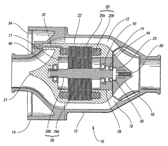
Figure 1 shows a longitudinal cross-sectional view of a fluid pump 10
in accordance with the present invention. A two-piece pump housing comprises
an
-5-


CA 02435654 2003-07-22
WO 02/063166 PCT/US02/02706
inlet pump housing 12 and an outlet pump housing 14. The pump housing has a
housing cavity 15 therein which contains an encapsulated stator assembly 22.
Referring to Figure 2, the encapsulated stator assembly 22 defines a
rotor cavity 17 with an opening 19. The encapsulated stator assembly 22
comprises
a polymeric capsule member 21, that has a plurality of diffuser vanes 18
molded
integrally thereon. Polymeric capsule member 21 encloses and seals a motor
stator
20 and motor power leads 32. Motor stator 20 comprises a plurality of steel
laminations 20a and a plurality of copper windings 20b.
Returning to Figure 1, located within rotor cavity 17 is a rotor
assembly 28, consisting of a rotor 28a and a rotor shaft 28b. The rotor shaft
28b is
supported by a front bearing 42 and a rear bearing 40. Rear bearing 40 is
located
within the encapsulated stator assembly 22. Front bearing 42 and seal 44 are
located
within the front cover 26 that plugs the rotor cavity opening 19.
Figure 3 shows a front perspective view of encapsulated motor
assembly 22. In particular, it shows diffuser vanes 18 which are of split
construction
(but need not be of split construction for this invention), and the motor
power leads
32 which are oriented with substantial circumferential symmetry around the
longitudinal axis of the encapsulated stator assembly 22. As seen in Figure 1,
motor
power leads 32 interface with a circuit board assembly 34.
Returning to Figure 1 impeller 16 is slip fit onto the rotor shaft 28b
and secured with a buttonhead capscrew 50. A drive pin 30 transversely located
through rotor shaft 28b drives impeller 16 via slot 23.
Figure 4 shows impeller 16 with slot 23 configured to receive drive
pin 30. Figure 5 shows the inlet pump housing 12 attached to the outlet pump
housing 14. Outlet pump housing 14 is again shown in Figure 6, this time with
motor power leads 32. Figure 7 shows the outside of pump 10 including the
inlet
pump housing 12, the outlet pump housing 14, the circuit board assembly 34,
and
-6-


CA 02435654 2003-07-22
WO 02/063166 PCT/US02/02706
the connection points between circuit board assembly 34 and the motor power
leads
32.
Referring to Figure 8, a fluid pump 60 is shown in accordance with
one alternative embodiment of the invention. Although similar in function to
the
preferred embodiment, there are a number of notable differences with regard to
form. Rather than a two-piece housing, this embodiment employs a three-piece
housing comprising an inlet housing 62, a stator housing assembly 64, and an
outlet
housing 66, assembled with bolts 68.
The stator housing assembly 64, shown in Figure 10 and sectioned in
Figure 11, includes an encapsulated stator assembly 75 and a substantially
cylindrical
metal case 73 which provides an outlet for a single bundle of motor power
leads 92
and diffuser vanes 83 that fully define the boundary of the working fluid. The
encapsulated stator assembly 75 includes a plurality of steel laminations 90a,
a
plurality of windings 90b, and a plurality of motor power leads 92. A
polymeric
capsule member 77 encloses and seals the stator assembly 90, and also defines
a
rotor cavity 79.
As shown in Figure 9, a rotor assembly 82, consisting of a rotor 82a
and a rotor shaft 82b, is located within rotor cavity 79. Rotor shaft 82b is
supported
by a rear bearing 96 positioned within the rear cover 74 which plugs the rear
opening
of the rotor cavity 79, and a front bearing 86 and seals 100 positioned within
a front
cover 70 which plugs the forward opening of the rotor cavity 79. Drive pin 84
is
positioned transversely through rotor shaft 82b and drives impeller 76.
Referring to Figure 9, unlike the preferred embodiment, this
alternative embodiment has two separate sets of diffuser vanes, the first set
81 being
configured on the front cover 70 and the second set 83 being configured on the
stator
housing assembly 64.
Figures 10 and 11 clearly show the resultant fluid passage 88 formed
between the vanes 83 and the inner and outer walls 73a,73b of the metal case
73.
_7_


CA 02435654 2003-07-22
WO 02/063166 PCT/US02/02706
The encapsulated stator assembly 75 may be manufactured by locating
the stator assembly 90 within the substantially cylindrical metal case 73 and
temporarily capping the two open ends of the metal case. The stator assembly
90
would then be encapsulated in a polymeric thermally conductive, electrically
insulative material 77. The opposing ends of the metal case would be uncapped,
and
the front and rear covers 70,74 would be attached to the metal case to
complete the
encapsulated stator assembly 75.
Figure 12 shows a second alternative embodiment of the fluid pump
of Figure 1. Seal cartridge assembly 26 plugs opening 19 in rotor cavity 17.
Wear
sleeve 24 is slip fit over the end of rotor shaft 52b. An impeller 16 is slip
fit onto
wear sleeve 24 and is secured to rotor shaft 52b with a buttonhead capscrew
50. A
drive pin 30 transversely located through rotor shaft 52b and wear sleeve 24
serves
multiple functions. The drive pin 30 drives impeller 16 via slot 23 (similarly
as
shown in Figure 4); it prevents wear sleeve 24 from rotating relative to rotor
shaft
52b; it captures axial loads from rotor assembly 52.
Some of the features and components of the seal cartridge assembly
26 are shown in Figures 12 and 13. Body 27 has a wet side 31 in contact with
the
working fluid, and a dry side 29. The body 27 also contains a plurality of
holes 47
for attaching the seal cartridge assembly 26 to the encapsulated stator
assembly 57,
using bolts 48. A seal 53 is press fit into the body 27 and plugs an opening
on the
wet side 31.
Referring to Figure 14, the wear sleeve 24 is machined to form an
inner diameter and has an axis coaxial to an axis of the body 27. A hole 25 is
machined transverse to the wear sleeve axis and is configured to receive drive
pin 30.
The rotor shaft 52b has a transverse hole 56 that also receives drive pin 30.
Returning to Figure 13, the front bearing 51, being press fit onto the
substantially cylindrical wear sleeve 24, plugs an opening on the dry side 29.
The
bearing 51 and wear sleeve 24 are press-fit into the cartridge body, and the
wear
sleeve 24 is slip fit over the shaft 52b. The seal cartridge assembly 26 also
contains
_g_


CA 02435654 2003-07-22
WO 02/063166 PCT/US02/02706
leak detection ports 33, shown in Figure 14, for visual or electronic
indication of seal
53 failure.
While embodiments of the invention have been illustrated and
described, it is not intended that these embodiments illustrate and describe
all
possible forms of the invention. Rather, the words used in the specification
are
words of description rather than limitation, and it is understood that various
changes
may be made without departing from the spirit and scope of the invention.
-9-

Representative Drawing
A single figure which represents the drawing illustrating the invention.
Administrative Status

For a clearer understanding of the status of the application/patent presented on this page, the site Disclaimer , as well as the definitions for Patent , Administrative Status , Maintenance Fee  and Payment History  should be consulted.

Administrative Status

Title Date
Forecasted Issue Date Unavailable
(86) PCT Filing Date 2002-01-30
(87) PCT Publication Date 2002-08-15
(85) National Entry 2003-07-22
Examination Requested 2003-09-11
Dead Application 2008-10-14

Abandonment History

Abandonment Date Reason Reinstatement Date
2007-10-12 FAILURE TO PAY FINAL FEE
2008-01-30 FAILURE TO PAY APPLICATION MAINTENANCE FEE

Payment History

Fee Type Anniversary Year Due Date Amount Paid Paid Date
Application Fee $300.00 2003-07-22
Request for Examination $400.00 2003-09-11
Registration of a document - section 124 $100.00 2003-09-11
Maintenance Fee - Application - New Act 2 2004-01-30 $100.00 2004-01-16
Maintenance Fee - Application - New Act 3 2005-01-31 $100.00 2004-10-06
Registration of a document - section 124 $100.00 2005-10-25
Maintenance Fee - Application - New Act 4 2006-01-30 $100.00 2006-01-12
Maintenance Fee - Application - New Act 5 2007-01-30 $200.00 2007-01-19
Owners on Record

Note: Records showing the ownership history in alphabetical order.

Current Owners on Record
EMP ADVANCED DEVELOPMENT, LLC
Past Owners on Record
BADER, MARK
CARLSON, JEREMY S.
DEGRAVE, KENNETH A.
ENGINEERED MACHINED PRODUCTS, INC.
LASECKI, MICHAEL P.
SHIVERSKI, STEVEN
Past Owners that do not appear in the "Owners on Record" listing will appear in other documentation within the application.
Documents

To view selected files, please enter reCAPTCHA code :


To view images, click a link in the Document Description column. To download the documents, select one or more checkboxes in the first column and then click the "Download Selected in PDF format (Zip Archive)" or the "Download Selected as Single PDF" button.

List of published and non-published patent-specific documents on the CPD .

If you have any difficulty accessing content, you can call the Client Service Centre at 1-866-997-1936 or send them an e-mail at CIPO Client Service Centre.


Document
Description 
Date
(yyyy-mm-dd) 
Number of pages   Size of Image (KB) 
Abstract 2003-07-22 1 56
Claims 2003-07-22 9 338
Description 2003-07-22 9 389
Drawings 2003-07-22 9 413
Cover Page 2003-09-15 1 35
Description 2003-07-23 9 399
Claims 2003-07-23 9 358
Description 2006-09-29 13 525
Claims 2006-11-01 11 328
Representative Drawing 2007-06-18 1 37
PCT 2003-07-22 17 940
Assignment 2003-07-22 3 91
Correspondence 2003-09-11 1 24
Assignment 2003-09-11 3 133
Prosecution-Amendment 2003-09-11 1 53
Assignment 2003-10-17 1 32
Prosecution-Amendment 2003-11-06 1 31
Fees 2004-01-16 1 38
Assignment 2005-10-25 3 99
Prosecution-Amendment 2006-03-30 4 143
Prosecution-Amendment 2006-09-29 14 485
Prosecution-Amendment 2006-10-25 1 19
Prosecution-Amendment 2006-11-01 2 33
Fees 2007-01-19 1 35