Note: Descriptions are shown in the official language in which they were submitted.
CA 02435850 2003-07-31
WO 01/53043 PCT/IE01/00008
-1-
"A Socket Wrench"
This invention relates to a socket wrench and in particular to multi-socket
wrenches -
or tools.
The invention particularly relates to a multiple socket wrench of a type
described in
our previously filed patent application No. PCT/IE97/00079 (publication No.
W098/22262) the contents of which are incorporated herein by reference. This
socket wrench has a tubular housing or body having at least two nesting
individual
socket wrench elements mounted on the housing, each of said socket elements
being axially moveable on the housing. Thus in use when one of the socket
wrench
elements is engaged with a nut or bolt each socket wrench element within the
socket
wrench element which is sized to engage the nut can retract within the housing
to
accommodate the nut. The socket wrench elements are arranged concentrically
within the housing. If dirt works its way between the socket wrench elements
then as
the socket wrench elements are engaged with a nut or the like as the inner
redundant
wrench socket elements retract they may pull the desired socket wrench element
inwardly also so it may not engage, or only partially engage the nut or bolt
head.
The present invention is directed toward overcoming this problem.
According to the invention there is provided a socket wrench of the multi-
socket type
for operation by an actuating lever, the socket comprising:-
a tubular body,
a set of nesting individual socket elements mounted on the body including at
least two co-axial socket elements, namely an inner socket element and an
outer socket element,
the inner socket element being movable axially inwardly relative to the outer
socket element to expose said outer socket element for use, and
CA 02435850 2003-07-31
WO 01/53043 PCT/IE01/00008
-2-
means for engaging the body with an actuating lever for rotation of the body
and hence the socket elements,
characterised in that locking means is provided for selectively locking each
movable individual socket on the body.
Thus advantageously the selected socket wrench element is prevented from
retracting on the housing when it is required for use ensuring full and
positive
engagement.
In one embodiment locking means comprises a selector switch on the body which
is
operable to position an associated selector pin on the body for engagement
with a
selected individual socket element to lock said selected individual socket
element on
the body.
In a preferred embodiment the selector switch is mounted in a slot in a side
wall of
the body, the selector switch extending through the slot to engage the
selector pin
which is mounted within the body, the selector pin being engagable with a
number of
spaced-apart grooves on an inside face of the body for alignment with each
individual
socket element, the selector switch being biased outwardly to engage the
selector pin
in the grooves, the selector switch being movable inwardly against said bias
to
disengage the selector pin from the grooves.
In a further embodiment each individual socket element has an outwardly
extending
lug at an inner end of said socket element for engagement with the selector
pin, said
lugs being engagable with an associated land within the body to retain the
individual
socket elements within the body, spring means mounted within the body to urge
each
socket element outwardly engaging the lug on the socket element with the land
on
the body.
In another embodiment the selector switch is slidably mounted in a
circumferential
slot in the side wall of the body and the selector pin is movable through an
arc within
the body between each socket element engaging position for alignment with the
lugs
on the socket elements.
CA 02435850 2003-07-31
WO 01/53043 PCT/IE01/00008
-3-
In another embodiment each lug extends outwardly from an inner end of the
socket
element in a generally radial direction and complementary slots are provided
at the
inner ends of the socket elements to allow through passage of lugs from any
inner
nested socket elements.
Conveniently the selector switch is mounted on a switch plate which is
releasably
mounted on the body side wall, said switch plate having an open-ended slot for
sliding reception of the switch and having a grooved inner surface for
reception and
alignment of the selector pin within the body.
In another embodiment a set of nesting individual socket elements is provided
at
each end of the body, each set of socket elements being housed within an
associated
end portion of the body.
In a particularly preferred embodiment two separate sets of socket elements
are
axially spaced-apart in the tubular body, said tubular body having a hollow
central
portion between end portions within which each set of socket elements is
mounted,
the hollow central portion being sized to accommodate only one set of socket
elements at a time.
In another embodiment a spring is mounted within the body engaged between the
innermost individual socket element in each set of nesting socket elements for
urging
the socket elements outwardly for engagement against the land on the body.
In a further embodiment means is provided at an end of the body for engagement
by
an actuating lever to rotate the body.
In a preferred embodiment each end portion of the body has a hexagonal outer
surface for engagement by an actuating lever.
In another embodiment the invention provides a socket wrench in combination
with
an adapter having a mounting socket for reception of each end of the body to
releasably mount the adapter on the body, said adapter having means for
CA 02435850 2003-07-31
WO 01/53043 PCT/IE01/00008
-4-
engagement with an actuating lever for rotating the adapter and socket wrench.
Preferably the adapter has a spring loaded locking ball mounted on an inside
wall of
the mounting socket which is engagable with complementary receiver slots at
each
end of the body to releasably retain the adapter on the body.
Conveniently an adapter drive is provided having a hexagonal drive socket at
one
end for engagement with the outer face of each end portion of the housing and
a
square section drive hole at the opposite end for reception of a standard
square drive
tool such as a T-bar, ratchet spanner or the like.
The invention will be more clearly understood by the following description of
some
embodiments thereof given by way of example only, with reference to the
accompanying drawings, in which;
Fig. 1 is a partially exploded perspective view of a multiple socket wrench of
the invention;
Fig. 2 is an elevational view of a housing portion of the socket wrench;
Fig. 3 is and end elevational view of the housing;
Fig. 4 is a plan view of a switch plate forming portion of a socket locking
mechanism for the socket wrench;
Fig. 5 is an end elevational view of the switch plate;
Fig. 6 is an elevational view of a selector pin forming portion of the locking
mechanism;
Fig. 7 is an end view of the selector pin;
Fig. 8 is a sectional view taken along the line VIII-VIII of Fig. 1;
CA 02435850 2003-07-31
WO 01/53043 PCT/IE01/00008
-5-
Fig. 9 is a perspective view of a socket wrench element forming portion of the
socket wrench;
Fig. 10 is a perspective view of a second socket wrench element;
Fig. 11 is a perspective view of a third socket wrench element;
Fig. 12 is a perspective view of a fourth socket wrench element;
Fig. 13 is a perspective view of an associated set of socket wrench elements;
Fig. 14 is a perspective view of another set of socket wrench elements; and
Fig. 15 is a perspective partially sectioned view of an adapter drive for the
socket wrench.
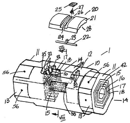
Referring to the drawings there is shown a socket wrench according to the
invention
indicated generally by the reference numeral 1. The socket wrench 1 has a
generally
tubular body 10 forming an outer housing having two opposed end portions 11 on
either side of a central portion 12. Each end portion 11 forms a hexagonal
socket
and has a hexagonal outer surface 13. Two sets of socket elements 14 are
mounted
on the body 10, each socket set 14 being nested within one of the end portions
11.
Each socket set 14 comprises a plurality of individual socket elements 15, 16,
17, 18
of different sizes arranged concentrically within the end portion 11 of the
body 10 and
slidable axially relative to each other for engaging a desired socket element
15, 16,
17, 18 with a nut or bolt head (not shown) in use.
To allow use of a desired socket element 15, 16, 17, 18 each socket element
15, 16,
17, 18 is axially moveable within the body 10 between an extended position
within the
outer end 11 and a retracted position within the central portion 12 of the
body 10. A
selector switch 20 is operable to lock each socket element 15, 16, 17, 18 when
desired to prevent retraction of said socket element 15, 16, 17, 18 into the
central
portion 12 of the body 10.
CA 02435850 2003-07-31
WO 01/53043 PCT/IE01/00008
-6-
Thus in use to engage a desired socket element 15, 16, 17, 18 with an
associated nut
or bolt head of a particular size the switch 20 is engaged with the
corresponding
socket element 15, 16, 17, 18 which is held against retraction whilst the
other socket
elements 15, 16, 17, 18 within the selected socket element 15, 16, 17, 18 are
free to
retract within the central portion 12 to allow reception of the nut or bolt
head within the
selected socket element 15, 16, 17, 18. It will be noted that the central
portion 12 is
sized to accommodate only one set of socket elements at a time, thus providing
a
compact construction.
The selector switch 20 comprises a switch plate 21 which is mounted within an
associated window 29 in a side wall of the central portion 12 of the body 10.
The
switch plate 21 has an associated selector pin 22 with a central projection 23
which
extends through a complementary open-ended guide slot 24 in the switch plate
21
and is attached to an operating button 25 which locates in and slides along a
recessed groove 26 in an outer face of the switch plate 21. A spring 27 is
provided
beneath the button 25 and extends between the button 25 and the outer face of
the
switch plate 21 to urge the selector pin 22 against an inside face 28 of the
switch
plate 21.
As can be seen in Fig. 5 the inside face 28 of the switch plate 21 has a
number of
spaced-apart grooves 30 each for reception of the selector pin 22 to retain
the
selector pin 22 at a desired location. To move the selector pin 22 the button
25 is
depressed against the spring 27 moving the selector pin 22 inwardly and then
the
button 25 can be slid along the groove 26 and released to allow the selector
pin to
snap into the selected groove 30 on the inside face of the selector plate 21.
Thus the
selector pin is mounted in an axial or longitudinal orientation within the
body 10.
At an inner end of each of the socket elements 15, 16, 17, 18 there is
provided a lug
32 associated with the selector pin 22. Thus when the selector pin 22 is
aligned with
a lug 32 it prevents the associated socket element 15, 16, 17, 18 from
retracting
within the central portion 12 of the body 10. As can be seen in Figs. 8-12,
with the
exception of the innermost socket element 15, each socket element 16, 17, 18
has a
slot 33 adjacent the lug 32 for through passage of lugs 32 of other socket
elements
15, 16, 17, 18 so that outer ends of the lugs 32 are arranged in a row within
the
CA 02435850 2003-07-31
WO 01/53043 PCT/IE01/00008
-7-
housing 10 in the path of the selector pin 22.
It will be noted that an outer end of each lug 32 bears against an associated
ledge or
land 35 within the window 22 to retain the socket elements 15, 16, 17, 18
within the
housing 10. A spring 38 extends between the innermost socket element 15 of
each
set 14 of socket elements to urge each set of socket elements 14 outwardly
with the
lugs 32 engaging against the land 35 for limiting outward movement. Each of
the
socket elements 15, 16, 17, 18 can be pushed inwardly against spring 38
pressure to
expose an outer socket element 15, 16, 17, 18 for use. As can be seen in Fig.
12 the
innermost socket element 15 has adjacent an inner end of its bore a step or
landing
40 against which an outer end of the spring 38 engages.
Figs 13 and 14 show the two sets of socket elements each set 14 comprising in
this
case four socket elements 15,16, 17, 18 which slidably nest one within the
other.
Thus advantageously in the socket wrench 1 advantageously ten different socket
element sizes are provided, with a hexagonal inside face 42 of each end
portion 11 of
the body 10 also forming a socket element.
Referring to Fig. 15 there is shown an adapter drive 50 which has at an inner
end a
hexagonal mounting socket 51 for engagement with the hexagonal outer face 13
at
each end 11 of the body 10. An inner end 52 of the adapter drive 50 has a
central
square section hole 53 for reception of a standard square drive T-bar, ratchet
spanner or the like actuating lever. The adapter drive 50 has a spring-loaded
locking
ball 55 mounted on an inside wall of the mounting socket 51 and projecting
outwardly
of said inside wall. This locking ball 55 is engagable with complementary
receiver
slots 56 on each flat face of the hexagonal ends 13 of the body 10. The ball
55 will
retract to allow the socket 51 of the adapter 50 to engage with the hexagonal
outer
surface 13 at each end of the body 10 and, on engagement, the ball 55 will
spring
outwardly for snap engagement within one of the slots 56 to securely retain
the
adapter 50 in engagement with the socket wrench 1.
In use a user manipulates the button 25 of the selector switch 20 to align the
selector
pin 22 with a desired socket element 15, 16, 17, 18 or disengage the selector
pin 22
altogether if the selected socket element is formed by the inside face 42 at
the end 11
CA 02435850 2003-07-31
WO 01/53043 PCT/IE01/00008
_g_
of the body 10. The .socket wrench 1 is then engaged with a nut or bolt with
the
socket element 11, 15, 16, 17, 18 being held steady whist redundant inner
socket
elements 15, 16, 17, 18 are pushed by the nut or bolt inwardly into the
central portion
12 of the body 10. Thus positive and secure engagement of the required socket
element 15, 16, 17, 18, 42 with the nut or bolt is achieved. It will be
appreciated that
the selector switch 20 can be quickly and easily operated to select any
desired socket
element 11, 15, 16, 17, 18, 42.
While all the sockets above have been described with reference to hexagonal
headed
nuts and bolts, and undoubtedly hexagonal headed nuts and bolts constitute the
majority of units which need to be actuated by a socket wrench, it will be
appreciated
that any other shape of multi-sided unit and corresponding socket could be
provided.
The invention is not limited to the embodiments hereinbefore described which
may be
varied in both construction and detail within the scope of the appended
claims.