Language selection

Search

Patent 2435974 Summary

Third-party information liability

Some of the information on this Web page has been provided by external sources. The Government of Canada is not responsible for the accuracy, reliability or currency of the information supplied by external sources. Users wishing to rely upon this information should consult directly with the source of the information. Content provided by external sources is not subject to official languages, privacy and accessibility requirements.

Claims and Abstract availability

Any discrepancies in the text and image of the Claims and Abstract are due to differing posting times. Text of the Claims and Abstract are posted:

  • At the time the application is open to public inspection;
  • At the time of issue of the patent (grant).
(12) Patent Application: (11) CA 2435974
(54) English Title: TORQUE DISCONNECT MECHANISM WITH BRAKE INTERLOCK
(54) French Title: MECANISME DE DEBRAYAGE AVEC DISPOSITIF DE BLOCAGE DE FREIN
Status: Dead
Bibliographic Data
(51) International Patent Classification (IPC):
  • F16H 57/00 (2012.01)
  • F16H 57/023 (2012.01)
  • F16H 61/22 (2006.01)
  • F16H 63/34 (2006.01)
  • F16H 63/48 (2006.01)
(72) Inventors :
  • ORE, THOMAS G. (United States of America)
(73) Owners :
  • DEERE & COMPANY (United States of America)
(71) Applicants :
  • DEERE & COMPANY (United States of America)
(74) Agent: BORDEN LADNER GERVAIS LLP
(74) Associate agent:
(45) Issued:
(22) Filed Date: 2003-07-25
(41) Open to Public Inspection: 2004-02-12
Examination requested: 2003-07-25
Availability of licence: N/A
(25) Language of filing: English

Patent Cooperation Treaty (PCT): No

(30) Application Priority Data:
Application No. Country/Territory Date
10/217,301 United States of America 2002-08-12

Abstracts

English Abstract


A vehicle transmission has first and second shafts rotatable in a housing, a
spring applied, pressure released bake mechanism for preventing vehicle
movement, and a torque disconnect mechanism for controlling transmission of
torque from the first shaft to the second shaft. An interlock mechanism
includes an
opening formed in the housing through which an operator may access the torque
disconnect mechanism, a fluid pressure supply passage for communicating
pressurized fluid to the brake mechanism, a dump port formed in the housing in
a
wall of the opening, a pressure dump passage communicating the supply passage
with the dump port, and a plug member mountable in the opening. The plug
member closes the dump port and closes communication between the dump
passage and the environment when the plug member is mounted in the opening
The dump port and the dump passage are communicated with the environment, and
the brake is spring applied when the plug member is removed from the opening.


Claims

Note: Claims are shown in the official language in which they were submitted.


I claim:

1. In a vehicle transmission having first and second shafts rotatable in a
housing, a spring applied, pressure released bake mechanism for preventing
vehicle
movement and a torque disconnect mechanism for controlling transmission of
torque
from the first shaft to the second shaft, an interlock mechanism comprising:

an opening formed in the housing through which an operator may access the
torque disconnect mechanism;

a fluid pressure supply passage for communicating pressurized fluid to the
brake mechanism;

a dump port formed in the housing in a wall of the opening;

a pressure dump passage communicating the supply passage with the dump
port; and

a plug member mountable in the opening, the plug member closing the dump
port and closing communication between the dump passage and the environment
when the plug member is mounted in the opening, and the dump port and the dump
passage being communicated with the environment when the plug member is
removed from the opening.

2. The interlock mechanism of claim 1, wherein:

the fluid pressure supply passage and the pressure dump passage are
formed in the housing.

3. A power transmission comprising:

first and second shafts rotatable in a housing;

a torque disconnect mechanism for controlling transmission of torque from the
first shaft to the second shaft;

an opening formed in the housing through which an operator may access the
torque disconnect mechanism;

a plug member removably mountable in the opening;
a bake mechanism operable to prevent rotation of the second shaft; and

an interlock mechanism operatively interconnecting the plug member and the
brake mechanism, the interlock mechanism operating to engage the brake
mechanism when the plug member is removed from the opening.


4


4. The power transmission of claim 3, wherein:

the brake mechanism comprises a spring applied, pressure released bake
communicated with a source of brake pressure via a supply passage; and

the interlock mechanism comprises a dump port formed in the housing in a
wall of the opening, a pressure dump passage communicating the supply passage
with the dump port, the plug member closing the dump port and closing
communication between the dump passage and the environment when the plug
member is mounted in the opening, and the dump port and the dump passage being
communicated with the environment when the plug member is removed from the
opening.

5. The interlock mechanism of claim 4, wherein:

the fluid pressure supply passage and the pressure dump passage are
formed in the housing.


5

Description

Note: Descriptions are shown in the official language in which they were submitted.


CA 02435974 2003-07-25
TORQUE DISCONNECT MECHANISM WITH BRAKE INTERLOCK
BACKGROUND OF THE INVENTION
The present invention relates to an interlock mechanism for operatively
coupling a torque disconnect mechanism and a brake mechanism in a vehicle.
When servicing or diagnosing a transmission it is desirable to disconnect
the transmission output shaft and prevent torque from being transmitted to the
output shaft. It has been proposed to have a torque disconnect mechanism which
includes a shift collar which is accessible though an opening in a
transmission
housing when a removable plug is removed from the opening. It would be
desirable
to prevent vehicle movement while an operator removes the plug to operate the
torque disconnect collar.
SUMMARY
Accordingly, an object of this invention is to provide a mechanism which
prevents vehicle movement while an operator manipulates a torque disconnect
mechanism.
These and other objects are achieved by the present invention, wherein a
transmission includes a parking brake which is spring engaged and which is
disengaged by hydraulic pressure. A torque disconnect mechanism controls
transmission of torque from a first shaft to a second shaft in a transmission.
The
torque disconnect mechanism includes a movable shift collar inside a housing.
The
shift collar is accessible through an opening in the housing. A plug member is
mounted in the opening and is removable to provide access to the shift collar.
The
housing includes a hydraulic fluid passage which communicates the park brake
pressure supply line to an aperture in the opening. When the plug member is
removed from the opening the aperture is opened to the environment, fluid
pressure
is relieved from the park brake pressure supply line and the park brake is
spring
applied.
BRIEF DESCRIPTION OF THE DRAWINGS
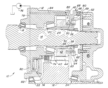
The sole Figure is a simplified partial sectional view of the present
invention.

CA 02435974 2003-07-25
DETAILED DESCRIPTION
A transmission 10 includes a housing 12 which rotatably supports a shaft 14
and a transmission output shaft 16. Shaft 14 may be a planetary output shaft
and
shaft 16 may be a transmission output shaft. Shaft 14 is supported by bearings
18
and 20, while shaft 16 is supported by bearings 22 and 24. A hollow hub gear
26 is
mounted on shaft 14. Gear 26 includes inner splines 28 which engage outer
splines
30 on the shaft 14. Gear 26 also includes outer splines 32.
A drive gear 40 is rotatably mounted on a portion of the hub gear 26. Drive
gear 40 includes a large diameter part 42 on which are formed splines 44.
Splines
44 engage corresponding splines 46 on shaft 16. Drive gear 40 also includes a
smaller diameter part 48 on which are formed splines 50 which are axially
adjacent
to splines 32 of hub gear 26.
An annular collar or coupling member 52 is mounted over the splines 50
and 32. Collar 52 has a generally cylindrical body with a pair of axially
spaced apart
sets of splines 54 and 56 separated by an radially inwardly opening annular
groove
58. The outer surface of the collar 52 forms a pair of lands 60 and 62
separated by
an outer annular groove 64.
Housing 12 includes an opening 66 through which an operator can access
the collar 52. A service disconnect plug 68 is removably mounted in the
opening 66.
Plug 68 includes a tab 69 which is engageable with the groove 64 in the collar
52.
The assembly also includes a conventional spring applied, pressure
released park brake 74 which is engageable to prevent rotation of output shaft
16. A
pressure source 76, which may be a conventional manually operated park brake
pump, supplies a limited volume of pressurized fluid to the park brake 74 via
brake
pressure supply passages 78 and 80 which are formed in the housing 12 and in a
park brake housing member 82. A pressure dump passage 84 is also formed in the
housing 12 and communicates passage 78 to a port 86 formed in the opening 70.
The collar 52 may be placed in an engaged position, shown in Fig. 1,
wherein splines 54 and 56 are in meshing engagement with splines 50 and 32,
respectively, and torque can be transmitted from shaft 14 to shaft 16.
2

CA 02435974 2003-07-25
To disengage shaft 14 from shaft 16, the plug 68 is removed from opening
66 and a tool (not shown) is inserted through opening 66 and into grove 64,
and the
tool is then manipulated to slide collar 52 to the right into the disengaged
position.
Removal of plug 68 from opening 66 opens port 86, communicates park brake 74
to
atmosphere via passages 80, 78 and 84, and causes park brake 74 to engage and
prevent rotation of shaft 16.
The plug 68 may then preferably re-oriented so that the tab 69 is oriented to
the right, and then plug 68 is re-inserted back into opening 66 so that tab 69
is
received by groove 64. Tab 69 thereby holds collar 52 in its disengaged
position
wherein splines 56 are uncoupled from splines 32 and torque cannot be
transmitted
from shaft 14 to shaft 16.
Plug 68 has a generally cylindrical head in which are formed a pair of
grooves for receiving O-ring seals. When plug 68 is installed in the opening
66 the
port 86 is sealed, and passages 84, 78 and 80, and the brake 74 remain
pressurized
and disengaged.
While the present invention has been described in conjunction with a
specific embodiment, it is understood that many alternatives, modifications
and
variations will be apparent to those skilled in the art in light of the
foregoing
description. Accordingly, this invention is intended to embrace all such
alternatives,
modifications and variations which fall within the spirit and scope of the
appended
claims.
3
Representative Drawing
A single figure which represents the drawing illustrating the invention.
Administrative Status

For a clearer understanding of the status of the application/patent presented on this page, the site Disclaimer , as well as the definitions for Patent , Administrative Status , Maintenance Fee  and Payment History  should be consulted.

Administrative Status

Title Date
Forecasted Issue Date Unavailable
(22) Filed 2003-07-25
Examination Requested 2003-07-25
(41) Open to Public Inspection 2004-02-12
Dead Application 2007-07-25

Abandonment History

Abandonment Date Reason Reinstatement Date
2006-07-25 FAILURE TO PAY APPLICATION MAINTENANCE FEE
2006-09-22 FAILURE TO PAY FINAL FEE

Payment History

Fee Type Anniversary Year Due Date Amount Paid Paid Date
Request for Examination $400.00 2003-07-25
Registration of a document - section 124 $100.00 2003-07-25
Application Fee $300.00 2003-07-25
Maintenance Fee - Application - New Act 2 2005-07-25 $100.00 2005-07-06
Owners on Record

Note: Records showing the ownership history in alphabetical order.

Current Owners on Record
DEERE & COMPANY
Past Owners on Record
ORE, THOMAS G.
Past Owners that do not appear in the "Owners on Record" listing will appear in other documentation within the application.
Documents

To view selected files, please enter reCAPTCHA code :


To view images, click a link in the Document Description column. To download the documents, select one or more checkboxes in the first column and then click the "Download Selected in PDF format (Zip Archive)" or the "Download Selected as Single PDF" button.

List of published and non-published patent-specific documents on the CPD .

If you have any difficulty accessing content, you can call the Client Service Centre at 1-866-997-1936 or send them an e-mail at CIPO Client Service Centre.


Document
Description 
Date
(yyyy-mm-dd) 
Number of pages   Size of Image (KB) 
Abstract 2003-07-25 1 27
Description 2003-07-25 3 137
Claims 2003-07-25 2 65
Drawings 2003-07-25 1 62
Representative Drawing 2003-10-01 1 35
Cover Page 2004-01-23 1 68
Assignment 2003-07-25 3 122