Note: Descriptions are shown in the official language in which they were submitted.
CA 02436036 2003-07-24
WO 02/081987 PCT/KR02/00589
APPARATUS AND METHOD FOR CONTROLLING COLD AIR
CIRCULATION IN REFRIGERATOR
BACKGROUND OF THE INVENTION
1. Field of the Invention
The present invention relates to a refrigerator, and more particularly, to an
apparatus for controlling cold air circulation in a refrigerator, which allows
the internal
temperature throughout a refrigerating chamber of the refrigerator to be
uniformly
1o distributed.
2. Description of the Prior Art
FIG. 6 shows a sectional view of a refrigerator which employs a conventional
apparatus for controlling cold air circulation therein. As shown in this
figure, a freezing
chamber 3 and a refrigerating chamber 5, which are storage spaces formed in
the interior
of a main body 1 of the refrigerator, are separated from..each. other by 'a
barrier 4. A
plurality of shelves 5' are installed at different levels in the refrigerating
chamber 5 so that
stored goods can be put on the shelves. A vegetable storage chamber 6 for
separately
storing fruits or vegetables therein is formed at a lowermost portion of the
refrigerating
chamber 5. In general, the vegetable storage chamber 6 is constructed in the
form of a
drawer.
The freezing chamber 3 and the refrigerating chamber 5 are opened and closed
by
doors 7, 7', respectively, so as to communicate with the exterior thereof.
Inner surfaces
of the doors 7, 7' are provided with door baskets 8 for accommodating stored
goods.
Meanwhile, an evaporator 9, which is one of constituent components of a heat
exchange cycle for generating cold air to circulate in the refrigerator, is
installed in the
rear of the freezing chamber 3. A space in which the evaporator 9 is installed
is shielded
by a shroud 10. A grill fan 12 is mounted between the shroud 10 and the
freezing
chamber 3. Further, in order to circulate the cold air generated by the
evaporator 9, a
blower fan 14 is installed above the evaporator 9. The blower fan 14 causes
the cold air
to flow into a space between the shroud 10 and the grill fan 12. The grill fan
12 is also
CA 02436036 2003-07-24
WO 02/081987 PCT/KR02/00589
2
provided with a discharge port (not shown) through which the cold air is
discharged to
the freezing chamber 3.
Moreover, the cold air which has flowed downward through between the shroud
and the grill fan 12 is supplied to the refrigerating chamber 5 through the
barrier 4.
5 To this end, a refrigerating chamber duct 16 is installed in the rear of the
refrigerating
chamber 5 such that it extends lengthily from an upper end of the
refrigerating chamber to
a lower end thereof. The refrigerating chamber duct 16 is formed with cold air
discharge
ports 17 through which the. cold air is discharged to spaces partitioned by
the shelves 5'.
Then, a freezing chamber return flow passage 18 is formed such that the
freezing
10 .,chamber 3 communicates with the space with the evaporator 9 installed
therein through a
top surface of the barrier 4 corresponding to a floor of the freezing chamber
3. The cold
air.'which has, circulated in the freezing chamber 3 is returned.to the
evaporator 9 through
the. freezing chamber return flow passage 18. Further,' a refrigerating
chamber return
flow passage 19 is formed such that the refrigerating chamber 5 communicates
with the
.15. space with the evaporator 9 installed therein through a bottom surface of
the. barrier 4
corresponding to a ceiling of the refrigerating chamber's.
'However; there are ~the= -following problems in the 'conventional --apparatus
for
controlling the cold air circulation constructed as such.
In the prior art, as a refrigeration cycle is operated and the blower fan 14
is also
20- driven, the cold air which has circulated in the refrigerating chamber 5
is delivered
through the refrigerating chamber return flow passage 19 to the evaporator 9
where heat
exchange occurs, and then circulates in the refrigerator. Therefore, during
the driving of
the refrigeration cycle, the temperature of the refrigerating chamber 5 is
relatively lowered
since a great deal of cold air is delivered to the refrigerating chamber 5. On
the contrary,
25 when the refrigeration cycle is stopped, the temperature of the
refrigerating chamber 5 is
rapidly increased in a state where there is no cold air flow. In such a way,
if the cold air
flow varies depending on the turning-on/off of the refrigeration cycle, the
temperature
deviation in the refrigerating chamber 5 becomes larger. Consequently,
freshness of the
stored goods is deteriorated.
30 Particularly, the cold air supplied to the refrigerating chamber '5 through
the
refrigerating chamber duct 16 is relatively less influenced by the blower fan
14. Further,
CA 02436036 2010-08-06
3
the cold air is relatively less delivered to the door baskets 8 spaced far
apart from the
discharge port 17. Thus, the temperatures of the door baskets 8 are relatively
higher
than those in the shelves 5' located at the same levels as the baskets 8. Such
a
phenomenon becomes severest at a position corresponding to the position of the
vegetable storage chamber 6, which is a position of the lowermost one of the
door
baskets 8.
Moreover, an actual temperature of the vegetable storage chamber 6 is
relatively higher than an optimum temperature therein. This is because there
is a
relatively little amount of cold air which flows toward a lower portion of the
refrigerating chamber duct 16 and is then delivered to the vegetable storage
chamber
6. That is, according to the prior art, the cold air is not uniformly
delivered to the
entire refrigerating chamber 5. Thus, it is likely that the temperature of a
lower
portion of the refrigerating chamber 5 becomes relatively higher, whereas the
temperature of an upper portion of the refrigerating chamber 5 becomes
relatively
lower.
Thus, there are disadvantages as described below. Since the temperature of the
refrigerating chamber 5 is not uniformly set in such a way, the freshness of
foodstuffs
stored in the lower portion of the refrigerating chamber 5 is deteriorated. In
addition,
since the cold air in the upper portion of the refrigerating chamber 5 is
returned to the
evaporator 9 in a state where the cold air is at a relatively lower
temperature, heat loss
occurs in the evaporator 9.
SUMMARY OF THE INVENTION
Illustrative embodiments may solve the aforementioned problems in the prior
art. Illustrative embodiments may minimize temperature deviation in a
refrigerating
chamber of a refrigerator.
Illustrative embodiments may maintain the temperature of a vegetable storage
chamber installed at a lower portion of the refrigerating chamber of the
refrigerator.
Illustrative embodiments may minimize heat loss of cold air which is returned
from the refrigerating chamber to an evaporator.
In accordance with one illustrative embodiment, there is provided an apparatus
for controlling cold air circulation in a refrigerator. The apparatus
includes: a cold air
supply means for supplying cold air, which has been generated by a heat
exchanger,
CA 02436036 2010-08-06
4
to a storage space by using a blower fan, the storage space having an upper
portion, a
middle portion, and a lower portion, the upper and lower portions each being
contiguous with the middle portion; a cold air supply flow passage with a
plurality of
cold air discharge ports corresponding to respective portions of the storage
space so
that the cold air supplied from the cold air supply means is delivered to the
storage
space; a cold air return flow passage for returning the cold air, which has
circulated in
the storage space, to the heat exchanger by means of suction force of the
blower fan; a
cold air circulation means comprising a circulation fan positioned at the
lower portion
of the storage space for causing the cold air, which has been supplied from
the cold
air supply flow passage to the storage space, to flow from the lower portion
of the
storage space only toward the lower or middle portion thereof; and a
microcomputer
for controlling the cold air supply means and the cold air circulation means
based on
information on temperature of the storage space so as to circulate the cold
air in the
refrigerator.
The cold air circulation means may further include a circulation duct of which
an inlet is disposed at the lower portion of the storage space and an outlet
is disposed
at the lower or middle portion of the storage space so as to deliver the cold
air sucked
by the circulation fan into the storage space again.
The circulation fan may be installed at the outlet or inlet of the circulation
duct.
The cold air circulation means may be installed within the cold air supply
flow
passage, or at a side wall of the storage space which is separate from the
cold air
supply flow passage.
The outlet of the circulation duct may be installed at the cold air discharge
port
of the cold air supply flow passage, and the inlet of the circulation duct may
be
positioned at the lower portion of the storage space.
The inlet of the circulation duct may be configured to communicate with a
lower portion of an auxiliary storage chamber which is separately formed at
the lower
portion of the storage space.
In accordance with another illustrative embodiment, there is provided an
apparatus for controlling cold air circulation in a refrigerator. The
apparatus includes:
a cold air supply device configured to supply cold air to a storage
compartment, the
storage compartment having an upper portion, a middle portion, and a lower
portion,
CA 02436036 2010-08-06
the upper and lower portions each being contiguous with the middle portion; a
cold air
supply flow passage having one or more cold air discharge ports configured to
deliver
the cold air supplied from the cold air supply device to the respective
portions of the
storage compartment; a cold air return flow passage configured to return the
cold air,
5 which has circulated in the storage compartment, to the cold air supply
device; and a
cold air circulation device comprising a circulation fan positioned in the
lower portion
of the storage compartment and configured to force cold air, which has been
supplied
from the cold air supply device, from the lower portion of the storage
compartment
only toward the lower or middle portion of the storage compartment.
In accordance with another illustrative embodiment, there is provided a
method for controlling cold air circulation in a refrigerator including a
blower fan for
circulating cold air, which has been generated by a heat exchanger, in storage
space,
and a circulation fan for circulating the cold air from a lower portion of the
storage
space to an upper portion thereof. The method involves: determining, by a
microcomputer, driving of the blower fan and the circulation fan through
comparison
of a sensed temperature of the storage space with a predetermined temperature;
driving the blower fan based on the determination of the microcomputer and
delivering the cold air, which has been generated by the heat exchanger, into
the
storage space; stopping the blower fan based on the determination of the
microcomputer; and only after said stopping, circulating the cold air, which
has been
delivered into the storage space, from the lower portion to the upper portion
of the
storage space by using the circulation fan.
BRIEF DESCRIPTION OF THE DRAWINGS
The above and other features and advantages of the invention will become
more apparent from reading the following description of preferred embodiments
taken
in connection with the accompanying drawings in which:
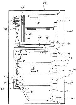
FIG. 1 is a sectional view showing the constitution of a refrigerator which
employs a preferred embodiment of an apparatus for controlling cold air
circulation in
the refrigerator according to the present invention;
FIG. 2 is a front perspective view showing the constitution of a refrigerating
chamber according to the embodiment shown in FIG. 1;
CA 02436036 2009-08-12
5a
FIG. 3 is a sectional view showing the constitution of a refrigerator which
employs another preferred embodiment of the present invention;
FIG. 4 is a partial front view showing the interior of the refrigerating
chamber,
when viewed in a direction indicated by an arrow A in FIG. 3;
FIG. 5 is a graph showing the temperature of the refrigerating chamber
depending on the temperature of a compressor in the apparatus for controlling
the
cold air circulation according to the present invention; and
FIG. 6 is a sectional view showing a conventional structure for a cold air
circulation flow in a refrigerator.
DETAILED DESCRIPTION OF THE INVENTION
Hereinafter, preferred embodiments of an apparatus and method for
controlling cold air circulation in a refrigerator according to the present
invention will
be described in
CA 02436036 2003-07-24
WO 02/081987 PCT/KR02/00589
6
detail with reference to the accompanying drawings.
.First, referring to FIGS. 1 and 2, one embodiment of the present invention
will be
described. As shown in these figures, the interior of a main body 30 of a
refrigerator,
which is comprised of walls having insulation layers, is provided with a
freezing chamber
33 and a refrigerating chamber 35 as storage spaces. The freezing chamber 33
and the
refrigerating chamber 35 are separated by a barrier 34 so that the freezing
chamber 33 and
the refrigerating chamber 35 are disposed at upper and lower portions of the
main body,
respectively.
A plurality of shelves 35' are installed in the refrigerating chamber 35 so
that
stored goods can be put: thereon. A vegetable storage chamber 36 as an
auxiliary storage
space, which is separately formed by means of partitions so as to store fruits
or vegetables,
is installed. at a lower portion within the refrigerating chamber 35.
The freezing chamber 33 and, the refrigerating chamber 35 selectively
communicate with the outside environment of the refrigerator by doors 37, 37',
respectively.... Inner surfaces of the doors 37, 37' are provided with a
plurality. of dogr
baskets 38 for accommodating stored goods.
Meanwhile; an - , evaporator 39 as a heat exchanger, = which ' constitutes va
refrigeration cycle; is installed, in- the rear of the freezing chamber .33 in
order to .genettte
cold air to circulate in the refrigerator. A space between the evaporator 39
and the
freezing chamber 33 is partitioned by a shroud 40 and a grill fan 42. A space
between
the shroud 40 and the grill fan 42 serves to distribute the cold air to the
freezing chamber
33 and the refrigerating chamber 35. Here, the grill fan 42 is formed with a
plurality of
discharge ports (not shown) through which the cold air is supplied to the
freezing
chamber 33. Further, a blower fan 44 which provides driving force for causing
the cold
air to flow in the refrigerator is installed above the evaporator 39.
In order to supply the cold air into the refrigerating chamber 35, a
refrigerating
chamber duct 46 is installed in the rear of the refrigerating chamber 35. The
refrigerating
chamber duct 46 extends lengthily from an upper end of the refrigerating
chamber to a
lower end thereof, and is formed with cold air discharge ports 47 to
correspond to the
respective shelves 35'. The cold air is delivered as far as the vegetable
storage chamber
36 through the refrigerating chamber duct 46.
CA 02436036 2003-07-24
WO 02/081987 PCT/KR02/00589
7
In order to return the cold air, which has circulated in the freezing chamber
33, to
the evaporator 39, a freezing chamber return flow passage 48 is formed through
the
interior of the barrier 34. Furthermore, in order to return the cold air,
which has
circulated in the refrigerating chamber 35, to the evaporator 39, a
refrigerating chamber
return flow passage 49 is formed through the interior of the barrier 34. An
inlet of the
refrigerating chamber return flow passage 49 is formed on a bottom surface of
the barrier
34 which becomes a ceiling of the refrigerating chamber 35.
Meanwhile, a circulation duct 50 is provided for further facilitating the cold
air
circulation in the lower portion of the refrigerating chamber 35.: Although
the circulation
duct 50 is installed in the refrigerating chamber duct 46..in this embodiment,
it is not
necessarily limited thereto. The circulation duct 50 may be installed at a
location, such
as. both side walls-.of the refrigerating chamber 35, separate from the
refrigerating chamber
duct 46.
- An inlet 51 of the circulation duct 50 is disposed at a rearward lower end
of the
15- vegetable storage chamber 36 to communicate with a lower -portion of the
vegetable
storage chamber 36. An outlet-52 of the circulation duct 50 is disposed to be
ope't1 to
above a shelf 35',which, is placed at a top end of the vegetable: storage
chamber36'At
this time, the outlet 52. is installed to penetrate -through- a, portion of a
front surface tithe
refrigerating chamber duct 46. The outlet 52 is also formed to communicate
with the
refrigerating chamber 35 via the cold air discharge port 47.
Further, the outlet 52 of the circulation duct 50 is provided with a
circulation fan
54 for circulating the cold air through the circulation duct 50. The
circulation fan 54
causes the cold air, which has been sucked through the inlet 51, to be
discharged into the
refrigerating chamber 35 through the outlet 52.
In the meantime, it is preferred that temperature sensors (not shown) be
mounted
so as to sense the temperatures within the refrigerating chamber 35, the
vegetable storage
chamber 36 and the like. Information on the temperature sensed by the
temperature
sensors are transmitted to a microcomputer (not shown) and then used for
determination
of the driving of the refrigeration cycle (i.e., driving of the blower fan 44)
and the driving
of the circulation fan 54. The microcomputer determines the driving of the
blower fan
44 and the circulation fan 54 based on predetermined data and the information
on the
CA 02436036 2003-07-24
WO 02/081987 PCT/KR02/00589
8
temperature sensed by the temperature sensors.
Hereinafter, the operation of the present embodiment having the aforementioned
constitution will be described.
First of all, the cold air circulation performed in the refrigerator will be
explained.
When the" refrigeration cycle is operated, a compressor (not shown) is driven
and a
refrigerant moves along the refrigeration cycle. Then, a relatively low
temperature
refrigerant is supplied to the evaporator 39 to generate the cold air.
The cold air generated by the evaporator 39 circulates in the refrigerator by
means of the blower fan 44. That is, the cold air is delivered to the space
between the
shroud 40- and the grill fan 42 by the driving of the blower fan 44, and then,
a portion of
the cold air is delivered to the freezing chamber 33 through the discharge
ports'of the grill
fan 42. The remainder of the cold air flows downward in the space between the
shroud
40 and the grill fan 42, passes through the barrier .34 and is supplied to the
refrigerating
chamber duct 46.
The cold air delivered to the refrigerating, chamber duct, 46 flows. downward
along the refrigerating chamber duct 46 and is. simultaneously discharged
through, the
respective discharge ports 47 'to above the respective -shelves 35" in the
refrigerating
chamber_.35. - The discharged cold air cools, the stored goods.. within the.
refrigerating
chamber 35. .
Then, the cold air which has been delivered-to the freezing chamber 33 and the
refrigerating chamber 35 is returned to the evaporator 39 .through the
freezing chamber
return flow passage 48 and the refrigerating chamber return flow passage 49,
respectively.
Heat exchange occurs between the cold air and the refrigerant in the
evaporator, and the
cold air then repeatedly circulates in the refrigerator.
Meanwhile, the circulation fan 54 sucks the cold air on a side of the lower
portion
of the refrigerating chamber 35 and discharges it upward. It is preferred that
the
circulation fan 54 be driven when the blower fan 44 is not operated. This is
to prevent
the vegetable storage chamber 36 from being cooled too excessively due .to
continuous
supply of the cold air, which is supplied from the evaporator 39 by the
operation of the
blower fan 44, to around the vegetable storage chamber 36.
Once the temperature of the refrigerating chamber 35 reaches a predetermined
CA 02436036 2003-07-24
WO 02/081987 PCT/KR02/00589
9
temperature, the operation of the heat exchange cycle is stopped and the
operation of the
blower fan 44 is also stopped. It is preferable to operate the circulation fan
54 in this
condition.
Namely, when the circulation fan 54 is operated, the cold air at the rearward
lower end of the vegetable storage chamber 36 is sucked through the inlet 51
of the
circulation duct 50. Then, the sucked cold air is discharged to above the
shelf 35' placed
at the top end of the vegetable storage chamber 36 through- the outlet 52 of
the circulation
duct 50. With such circulation, a space between a leading end of the vegetable
storage
chamber 36 and the door 37' is supplied with the-cold air from the upper
portion of the
. refrigerating chamber 3.5. Here, the cold air delivered from the upper.
portion of the
refrigerating chamber 35 passes through around the vegetable storage chamber
36 and is
sucked- into the inlet 51 of the circulation duct 50. This cold air,
circulation is indicated-.
by arrows in FIGS. I and 2.
In such a way, the relatively low temperature cold air can be delivered
particularly
.15 to around the vegetable storage chamber 36 as well as the door baskets'38'
of thefdoor
37'. Further, the.- relatively low temperature cold air can also be
delivered..:,,to a
lowermost door: basket - 38' of the door 37' which otherwise- might have ~a
highest
temperature.. Thus, the lowermost basket 38' can be set.at'a desired
temperature.,;
Such an operation of the circulation fan 54 can be controlled based on sensed
signals detected by a temperature sensor additionally installed in the
vegetable storage
chamber 36. That is, when the temperature of the vegetable storage chamber 36
reaches
a predetermined temperature, the circulation fan 54 is stopped in response to
the sensed
signals detected by the temperature sensor.
Next, another embodiment of the present invention is shown in FIGS.. 3 and 4.
When describing the constitution of this embodiment, only elements different
from those
of the previous embodiment shown in FIG. 1 will be described and like or
similar elements
are denoted by the same reference numerals as FIG. 1.
In order to further facilitate the cold air circulation in the refrigerating
chamber 35,
the present embodiment employs a circulation duct 150. The circulation duct
150 of the
present embodiment is not also necessarily installed in the refrigerating
chamber duct 46
and may be installed at a location, such as both the side walls of the
refrigerating chamber
CA 02436036 2003-07-24
WO 02/081987 PCT/KR02/00589
35, separate from the refrigerating chamber duct 46.
A circulation fan 152 is installed at an inlet 151 which is disposed at a
lower end
of the circulation duct 150. The inlet 151 of the circulation duct 150 is
fitted into and
installed at a circulation inlet 47' of the refrigerating chamber duct 46.
Thus, the
5 circulation fan 152 is positioned inside the circulation inlet 47' so that
the cold air within
the refrigerating chamber 35 can be sucked thereinto.
The circulation duct 150 is installed in the refrigerating chamber duct 46 to
extend lengthily in-an up and down direction and is provided with respective
outlets 154
at locations corresponding to the discharge ports 47 formed in the
refrigerating chamber
10 duct 46. The outlets 154-are formed at the locations corresponding to the-
discharge
ports 47 so that the cold air flowing through the circulation duct 150 can be
supplied to
the refrigerating chamber-35 through the discharge ports 47.. At this time; it
is preferable
to make cross-sectional areas of the outlets 154 smaller than those of the
discharge ports
47. Further, although each outlet 154 can be installed to be fitted into a
portion of each
discharge port 47,= it is not necessarily limited thereto. The outlets 154 may
be arranged
to be disposed, in the vicinity of the discharge ports 47 in the same way as
the illustrated
embodiment.
Hereinafter, the. operation of the present embodiment as 'constructed as such
will
be briefly described. The present embodiment is the same as. the previous
embodiment in
that the cold air generated' by the evaporator 39 is delivered to the freezing
chamber 33
and the refrigerating chamber 35 by means of the blower fan 44, and in that
the cold air
delivered to the freezing chamber. 33 and the refrigerating chamber 35 is
returned through
the respective freezing chamber return flow passage 48 and refrigerating
chamber return
flow passage 49 to the evaporator 39 where the heat exchange occurs between
the cold
air and the refrigerant in the evaporator and then repeatedly circulates in
the refrigerator.
Meanwhile,.the circulation fan 152 sucks the cold air on a.side of the
interior of
'the refrigerating chamber 35 and then discharges it to the other side. It is
preferable to
drive the circulation fan 152 when the blower fan 44 is not operated.
Alternatively, the
circulation fan 152 may be driven together with the blower fan 44 so that the
relatively
low temperature cold air cannot be returned to the evaporator 39.
Once the temperature of the refrigerating chamber 35 reaches a predetermined
CA 02436036 2003-07-24
WO 02/081987 PCT/KR02/00589
11
temperature, the operation of the heat exchange cycle is stopped and the
operation of the
blower fan 44 is also stopped. It is preferable to operate the circulation fan
152 in this
condition.
That is, the temperatures in the vicinity of the lower portion and the
vegetable
storage chamber 36 of the refrigerating chamber 35 are generally higher than
the
predetermined temperature. This is because the lower portion and the vegetable
storage
chamber 36 of the refrigerating chamber 35 are portions corresponding to a
distal end of
the refrigerating chamber duct 46.
Therefore, when the circulation fan 152 is operated, the cold air flow
indicated by
arrows in FIGS. - 3 and 4 is generated within the refrigerating chamber 35.
With such
cold air flow, the entire interior of the refrigerating chamber 35 can be kept
at a uniform
temperature.
In other words, when the circulation fan 152 is operated, the cold air at the
lower
portion of the refrigerating chamber 35 is sucked into the circulation duct
150 through the
circulation inlet 47'. Then, the sucked cold air. is delivered to an upper
portionof the.
circulation duct 150 and discharged to a relatively upper, portion of the
refrigerating..
chamber 35 through the respective outlets 154.
In particular, the cold 'air around the vegetable storage chamber 36 is sucke4
into
the circulation duct 150 by means of the driving of the. circulation fan 152
and the cold air
at the upper portion of the refrigerating chamber 35 is simultaneously-moved
downward,
so that the temperature of the entire refrigerating chamber 35 can be kept to
be uniform.
Referring to FIG. 5, there is well shown that the temperature of the
refrigerating
chamber -35 according to the present invention is kept to be relatively
uniform as time
passes. The temperature of the compressor is plotted using a dotted line. The
higher
temperature of the compressor means that the refrigeration cycle is running.
The
temperature of the refrigerating chamber depending on the temperature of the
compressor
is plotted using a one-dotted chain line in case of the prior art and using a
solid line in case
of the present embodiment. As can be seen from this figure, in case of the
present
embodiment, the temperature deviation with the elapse of time is relatively
small and thus
the refrigerating chamber is kept at a substantially uniform temperature.
With the apparatus and method for controlling the cold air circulation in the
CA 02436036 2003-07-24
WO 02/081987 PCT/KR02/00589
12
refrigerator according to the present invention which have been described in
detail above,
the temperature of the entire refrigerating chamber can be kept to be uniform,
and
particularly, the vegetable storage chamber disposed at the lowermost portion
of the
refrigerating chamber and the lowermost door basket of the door can be
maintained at a
desired temperature.
Furthermore, according to the present invention, since the temperature of the
entire refrigerating chamber can be kept to be uniform, the relatively low
temperature cold
air is prevented from being delivered to and heat-exchanged with the
evaporator. Thus,
the efficiency of the refrigerator can be improved.
Although the present invention has been described herein with respect to the
preferred embodiments employed in an upright type refrigerator, it will be
understood by
.those skilled in the art that the present invention can be employed in a
paralfie'1 type
refrigerator within the scope of the invention defined by the appended claims.