Language selection

Search

Patent 2436105 Summary

Third-party information liability

Some of the information on this Web page has been provided by external sources. The Government of Canada is not responsible for the accuracy, reliability or currency of the information supplied by external sources. Users wishing to rely upon this information should consult directly with the source of the information. Content provided by external sources is not subject to official languages, privacy and accessibility requirements.

Claims and Abstract availability

Any discrepancies in the text and image of the Claims and Abstract are due to differing posting times. Text of the Claims and Abstract are posted:

  • At the time the application is open to public inspection;
  • At the time of issue of the patent (grant).
(12) Patent: (11) CA 2436105
(54) English Title: CLUTCH CONNECTION/DISCONNECTION DETECTION SYSTEM FOR SINGLE-CYLINDER ENGINE
(54) French Title: SYSTEME DE DETECTION D'ACCOUPLEMENT/DE DESACCOUPLEMENT D'EMBRAYAGE POUR MOTEUR MONOCYLINDRIQUE
Status: Deemed expired
Bibliographic Data
(51) International Patent Classification (IPC):
  • F02D 35/00 (2006.01)
  • F16D 48/06 (2006.01)
(72) Inventors :
  • HIROSHI, TANAKA (Japan)
(73) Owners :
  • HONDA GIKEN KOGYO KABUSHIKI KAISHA (Japan)
(71) Applicants :
  • HONDA GIKEN KOGYO KABUSHIKI KAISHA (Japan)
(74) Agent: DENNISON ASSOCIATES
(74) Associate agent:
(45) Issued: 2007-12-04
(22) Filed Date: 2003-07-14
(41) Open to Public Inspection: 2004-01-17
Examination requested: 2003-07-14
Availability of licence: N/A
(25) Language of filing: English

Patent Cooperation Treaty (PCT): No

(30) Application Priority Data:
Application No. Country/Territory Date
2002-207799 Japan 2002-07-17

Abstracts

English Abstract

To detect with high accuracy the connection/disconnection of a clutch intermediately provided between a crankshaft of a single-cylinder engine and a power transmission means for transmitting the output of the crankshaft. The rotation variation coefficient of a crankshaft 7 is detected by a rotation variation coefficient detection means 16, and a decision means 17 decides the connection/disconnection of a clutch 11 by comparing the rotation variation coefficient detected by the rotation variation detection means 16 with a preliminarily determined threshold.


French Abstract

Pour détecter avec une grande précision la connexion / déconnexion d'un embrayage intermédiaire prévu entre un vilebrequin d'un moteur mono-cylindre et des moyens de transmission de puissance afin de transmettre la sortie du vilebrequin. Le coefficient de variation de rotation d'un vilebrequin 7 est détecté par des moyens de détection de coefficient de variation de rotation 16, et des moyens de détermination 17 déterminent la connexion / déconnexion d'un embrayage 11, en comparant le coefficient de variation de rotation détecté par les moyens de détection de variation de rotation 16 à un seuil déterminé au préalable.

Claims

Note: Claims are shown in the official language in which they were submitted.


-7-
THE EMBODIMENTS OF THE INVENTION IN WHICH AN EXCLUSIVE
PROPERTY OR PRIVILEGE IS CLAIMED ARE DEFINED AS FOLLOWS:

1. A clutch connection/disconnection detection system for a single-
cylinder engine, for detecting the connection/disconnection of a clutch
intermediately provided between a crankshaft of said single-cylinder engine
and
a power transmission mechanism that transmits the output of said crankshaft
comprising: a rotation variation coefficient detector that detects the
rotation
variation coefficient of said crankshaft, the rotation variation coefficient
being a
coefficient that changes with engine speed; and a decision mechanism that
decides the connection/disconnection of said clutch by comparing said rotation

variation coefficient detected by said rotation variation coefficient detector
with a
preliminarily determined threshold, wherein the rotation variation coefficient
is a
ratio of the time of a compression stroke and an exhaust stroke of the engine
with
respect to the time for two revolutions of the crankshaft.

2. The clutch connection/disconnection detection system for a single-
cylinder engine as set forth in claim 1, wherein said threshold is
preliminarily set
according to engine speed.

3. The clutch connection/disconnection detection system for a single-
cylinder engine as set forth in claim 1, and further including a rotating disk

operatively connected to the crankshaft for rotation therewith and a pulser
displaced a predetermined distance relative to the rotating disk for detecting
the
rotation thereof.

4. The clutch connection/disconnection detection system for a single-


-8-
cylinder engine as set forth in claim 3, wherein a plurality of projections
extend
from the rotating disk and said pulser detects each projection during rotation
for
outputting a pulse signal for each time a projection is detected.

5. The clutch connection/disconnection detection system for a single-
cylinder engine as set forth in claim 4, wherein nine projections extend from
the
rotating disk and wherein pulse signals for stages 0 to 17 are assigned during
two
revolutions of the crankshaft.

6. The clutch connection/disconnection detection system for a single-
cylinder engine as set forth in claim 5, wherein stages 4 to 6 correspond to a
combustion stroke of the engine.

7. The clutch connection/disconnection detection system for a single-
cylinder engine as set forth in claim 5, wherein stages 7 to 12 correspond to
an
exhaust stroke of the engine.

8. The clutch connection/disconnection detection system for a single-
cylinder engine as set forth in claim 5, wherein stages 13 to 15 correspond to
an
intake stroke of the engine.

9. The clutch connection/disconnection detection system for a single-
cylinder engine as set forth in claim 5, wherein stages 16 to 3 correspond to
a
compression stroke of the engine.

10. The clutch connection/disconnection detection system for a single-


-9-
cylinder engine as set forth in claim 1, wherein the rotation variation
coefficient is
calculated as follows: TSRAT=(TSA4-TSH4)/ME4U where: TSRAT is the rotation
variation coefficient, TSA4 is the time of a compression stroke of the engine,
TSH4 is the time of the exhaust stroke of the engine, and ME4U is the time for
two revolutions of the crankshaft.

11. A method for detecting clutch connection/disconnection for a
single-cylinder engine, for detecting the connection/disconnection of a clutch
intermediately provided between a crankshaft of said single-cylinder engine
and
a power transmission mechanism that transmits the output of said crankshaft,
said method comprising the following steps: detecting a rotation variation
coefficient of said crankshaft, the rotation variation coefficient being a
coefficient
that changes with engine speed; and deciding the connection/disconnection of
said clutch by comparing said rotation variation coefficient of the crankshaft
with
a preliminarily determined threshold, wherein the rotation variation
coefficient is
a ratio of the time of a compression stroke and an exhaust stroke of the
engine
with respect to the time for two revolutions of the crankshaft.

12. The method for detecting clutch connection/disconnection for a
single-cylinder engine as set forth in claim 11, wherein said threshold is
preliminarily set according to engine speed.

13. The method for detecting clutch connection/disconnection for a
single-cylinder engine as set forth in claim 11, wherein the detecting step
includes
a rotating disk operatively connected to the crankshaft for rotation therewith
and
a pulser displaced a predetermined distance relative to the rotating disk for


-10-
detecting the rotation thereof.

14. The method for detecting clutch connection/disconnection for a
single-cylinder engine as set forth in claim 13, wherein a plurality of
projections
extend from the rotating disk and said pulser detects each projection during
rotation for outputting a pulse signal for each time a projection is detected.

15. The method for detecting clutch connection/disconnection for a
single-cylinder engine as set forth in claim 14, wherein nine projection
extend
from the rotating disk and wherein pulse signals for stages 0 to 17 are
assigned
during two revolutions of the crankshaft.

16. The method for detecting clutch connection/disconnection for a
single-cylinder engine as set forth in claim 15, wherein stages 4 to 6
correspond to
a combustion stroke of the engine.

17. The method for detecting clutch connection/disconnection for a
single-cylinder engine as set forth in claim 15, wherein stages 7 to 12
correspond
to an exhaust stroke of the engine.

18. The method for detecting clutch connection/disconnection for a
single-cylinder engine as set forth in claim 15, wherein stages 13 to 15
correspond
to an intake stroke of the engine.

19. The method for detecting clutch connection/disconnection for a
single-cylinder engine as set forth in claim 15, wherein stages 16 to 3
correspond


-11-
to a compression stroke of the engine.

20. The method for detecting clutch connection/disconnection for a
single-cylinder engine as set forth in claim 11, wherein the rotation
variation
coefficient is calculated as follows: TSRAT=(TSA4-TSH4)/ME4U where: TSRAT is
the rotation variation coefficient, TSA4 is the time of a compression stroke
of the
engine, TSH4 is the time of the exhaust stroke of the engine, and ME4U is the
time for two revolutions of the crankshaft.

21. A clutch connection/disconnection detection system for a single-
cylinder engine for detecting the

connection/disconnection of a clutch intermediately provided between a
crankshaft of said single-cylinder engine and a power transmission mechanism
that transmits the output of said crankshaft comprising: a rotation variation
coefficient detector that detects the rotation variation coefficient of said
crankshaft; and a decision mechanism that decides the connection/disconnection
of said clutch by comparing said rotation variation coefficient detected by
said
rotation variation coefficient detector with a preliminarily determined
threshold,
wherein said decision mechanism decides that said clutch is connected when
said
rotation variation coefficient is below the preliminarily determined threshold
and
that said clutch is disconnected when said rotation variation coefficient is
above
the preliminarily determined threshold.

22. A method for detecting clutch connection/disconnection for a
single-cylinder engine for detecting the connection/disconnection of a clutch
intermediately provided between a crankshaft of said single-cylinder engine
and


-12-

a power transmission mechanism that transmits the output of said crankshaft,
said method comprising the following steps: detecting a rotation variation
coefficient of said crankshaft; and deciding the connection/disconnection of
said
clutch by comparing said rotation variation coefficient of the crankshaft with
a
preliminarily determined threshold, wherein the step of deciding decides that
said clutch is connected when said rotation variation coefficient is below the

preliminarily determined threshold and that said clutch is disconnected when
said rotation variation coefficient is above the preliminarily determined
threshold.


Description

Note: Descriptions are shown in the official language in which they were submitted.


CA 02436105 2003-07-14

CLUTCH CONNECTION/DISCONNECTION DETECTION SYSTEM FOR
SINGLE-CYLINDER ENGINE

FIELD OF THE INVENTION
The present invention relates to a clutch connection/disconnection
detection system for a single-cylinder engine, for detecting the
connection/disconnection of a clutch intermediately provided between a
crankshaft of the single-cylinder engine and a power transmission means
for transmitting the output of the crankshaft.

BACKGROUND OF THE INVENTION
Conventionally, in the case of detecting the connection/disconnection of a
manual clutch, the connection/disconnection of the clutch has been
detected by detecting the operation of a manual lever with a switch
disposed in the vicinity of the manual switch, and in the case of a
centrifugal clutch, the connection/disconnection of the clutch has been
decided by the rotational frequency of the crankshaft based on the
characteristic of the clutch.
Meanwhile, information on the connection/disconnection of the clutch is
needed in the case of, for example, performing an idling control of the
engine. Since a low detection accuracy leads to a lowering of idling
stability, it is required to detect the connection/disconnection of the clutch
with high accuracy. However, the above-mentioned detection systems
according to the prior art cannot be said to be capable of detecting the
connection/disconnection of the clutch with high accuracy.

The present invention has been made in consideration of the above
circumstances. Accordingly, it is an object of the present invention to
JJ-12054/cs


CA 02436105 2003-07-14

-2-
provide a clutch connection/disconnection detection system for a single-
cylinder engine by which the connection/disconnection of the clutch can
be detected with high accuracy.

SUMMARY OF THE INVENTION
In order to attain the above object, the present invention provides a clutch
connection/disconnection detection system for a single-cylinder engine,
for detecting the connection/disconnection of a clutch intermediately
provided between a crankshaft of the single-cylinder engine and a power
transmission means for transmitting the output of the crankshaft, which
includes a rotation variation coefficient detection means for detecting the
rotation variation coefficient of the crankshaft, and a decision means for
deciding the connection/disconnection of the clutch by comparing the
rotation variation coefficient detected by the rotation variation coefficient
detection means with a preliminarily determined threshold.

Meanwhile, the angular moment of the crankshaft varies depending on
the connection/disconnection of the clutch, and the rotation variation
coefficient of the crankshaft also varies with the varying angular moment.
Therefore, when the connection/disconnection of the clutch is decided
based on the rotation variation coefficient of the crankshaft by the above
constitution according to the invention as set forth above, the
connection/disconnection of the clutch can be detected accurately without
need for a special switch or sensor.
According to an aspect, the invention is characterized in that, in addition
to the constitution of the invention as set forth above, the threshold is
preliminarily set according to engine speed. With this constitution, the
connection/disconnection of the clutch can be detected accurately in the
manner of being adapted to variations in the operating condition of the
engine.

BRIEF DESCRIPTION OF THE DRAWINGS

Preferred embodiments of the invention are shown in the drawings,
wherein:

JJ-12054/cs


CA 02436105 2003-07-14

-3-
Fig. 1 is a schematic diagram showing a part of a power transmission
system of a single-cylinder engine.

Fig. 2 is a sectional view taken along line 2-2 of Fig. 1.
Figs. 3(a) and 3(b) are diagrams showing an output signal from a pulser.
Fig. 4 is a diagram showing a table of threshold.

DETAILED DESCRIPTION OF THE PREFERRED EMBODIMENTS
Now, a mode for carrying out the present invention will be described
below based on an embodiment of the invention shown in the
accompanying drawings.
Figs. 1 to 4 show an embodiment of the present invention, in which Fig. 1
is a schematic diagram showing a part of a power transmission system of a
single-cylinder engine, Fig. 2 is a sectional view taken along line 2-2 of
Fig.
1, Figs. 3(a) and 3(b) are diagrams showing an output signal from a pulser,
and Fig. 4 is a diagram showing a table of threshold.

First, in Fig. 1, a four-cycle single-cylinder engine 5 mounted, for example,
on a motorcycle or the like includes a single piston 6, which is connected
to a crankshaft 7 through a connecting rod 8. One end of the crankshaft 7
is connected, through a centrifugal clutch 11, to a drive pulley 10 of a belt-
type continuously variable transmission 9 serving as a power
transmission means for transmitting the power of the crankshaft 7 to the
side of rear wheels (not shown) while changing the speed. In addition, an
AC generator 12 or the like is connected to the other end of the crankshaft
7.

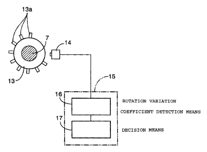
Referring to Fig. 2 also, a circular rotating disk 13 provided on its outer
circumference with a plurality of, for example, nine projections 13a is
coaxially attached to the crankshaft 7, and a pulser 14 for detecting each of
the projections 13a and outputting a pulse signal each time of the
detection is fixedly disposed so as to face the outer circumference of the
rotating disk 13.

JJ-12054/cs


CA 02436105 2006-01-16
4

According to the rotation of the crankshaft 7 and the rotating disk 13, the
pulser
14 outputs the puLse signals as shown in Fig. 3(a). When numerals 0 to 17 are
assigned to stages between the piulse signals during two revolutions of the
crankshaft 7 as shown in Fig. 3(b), stages 4 to 6 correspond to the combustion
stroke, stages 7 to 12 correspond to the exhaust stroke, stages 13 to 15
correspond
to the intake stroke, and stages 16 to 3 correspond to the compression stroke.
Times TSN4, TSH4, TSK4, and TSA4 of the combustion, exhaust, intake, and
compression strokes during two revolutions of the crankshaft 7 in a time ME4U
can be obtained by integrating the tirnes of the stages for each of the
strokes.

The output signal from the pulser 14 is inputted to an electronic control unit
15
for controlling the operation of the engine 5. The electronic_control unit 15
has
the function of detecting the connection/disconnection of the centrifugal
clutch
11, and the part for detecting the connection/disconnection of the centrifugal
dutch 11 indudes a rotation variation coefficient detection means 16 for
detecting
the rotation variation coefficient of ttie crankshaft 7, and a decision means
17 for
deciding the connection/disconnection of the centrifugal clutch 11 by
comparing
the rotation variation coefficient dei:ected by the rotation variation
coefficient
detection means 16 with a preliminarily determined threshold.

In the rotation variation coefficient detection means 16, for example, the
rotation
variation coefficient TSRAT is calculated according to the following
arithmetic
formula by use of the time TSH4 of the exhaust stroke, the time TSA4 of the
compression stroke, and the time M[E4U required for two revolutions of the
crankshaft 7.

TSRAT = (T5A4 - T5H4)/MB4U
The decision means 17 decides the connection/disconnection of the centrifugal
dutch 11 by use of the table of the threshold TSRATS shown in Fig. 4. The
threshold TSRATS is preliminarily dE:termined so as to vary according to the
engine speed Ne.


CA 02436105 2003-07-14

-5-
Meanwhile, the angular moment of the crankshaft 7 varies depending on
the connection/disconnection of the centrifugal clutch 11, and the rotation
variation coefficient TSRAT of the crankshaft 7 varies with the varying
angular moment. Specifically, the rotation variation coefficient TSRAT of
the crankshaft 7 is small when the centrifugal clutch 11 is in the connected
condition, whereas the rotation variation coefficient TSRAT of the
crankshaft 7 is greater when the centrifugal clutch 11 is in the disconnected
condition. When the rotation variation coefficient TSRAT obtained by
the rotation variation coefficient detection means 16 is not less than the
threshold TSRATS shown in Fig. 4, the decision means 17 decides that the
centrifugal clutch 11 is in the disconnected condition; when the rotation
variation coefficient TSRAT obtained by the rotation variation coefficient
detection means 16 is less than the threshold TSRATS shown in Fig. 4, the
decision means 17 decides that the centrifugal clutch 11 is in the connected
condition.

By deciding the connection/disconnection of the centrifugal clutch 11
based on the rotation variation coefficient TSRAT of the crankshaft 7, and
by utilizing the fact that the angular moment of the crankshaft 7 varies
depending on the connection/disconnection of the centrifugal clutch 11, as
above-described, the connection/disconnection of the centrifugal clutch 11
can be detected with high accuracy, without need for a special switch or
sensor.

Moreover, since the threshold TSRATS for deciding the
connection/disconnection of the centrifugal clutch 11 is preliminarily
determined according to the engine speed Ne, the
connection/disconnection of the centrifugal clutch 11 can be detected
accurately in the manner of being adapted to variations in the operating
condition of the engine.

While the embodiment of the present invention has been described
above, the invention is not limited to the above embodiment, and various
design modifications are possible without departing from the invention as
defined in the claims.

JJ-12054/cs


CA 02436105 2003-07-14

-6-
For example, while description has been made of the centrifugal clutch 11
in the above embodiment, the present invention is widely applicable to as
a system for detecting the connection/disconnection of a clutch
intermediately provided between the crankshaft 7 of the single-cylinder
engine 5 and the power transmission means 9 for transmitting the output
of the crankshaft 7.

As described above, according to the invention, the
connection/disconnection of the clutch is decided based on the rotation
variation coefficient of the crankshaft, whereby the
connection/disconnection of the clutch can be detected accurately, without
need for a special switch or sensor.

In addition, according to a preferred embodiment of the invention, the
connection/disconnection of the clutch can be detected accurately in the
manner of being adapted to variations in the operating condition of the
engine.

Although various preferred embodiments of the present invention have
been described herein in detail, it will be appreciated by those skilled in
the
art, that variations may be made thereto without departing from the spirit
of the invention or the scope of the appended claims.

JJ-12054/cs

Representative Drawing
A single figure which represents the drawing illustrating the invention.
Administrative Status

For a clearer understanding of the status of the application/patent presented on this page, the site Disclaimer , as well as the definitions for Patent , Administrative Status , Maintenance Fee  and Payment History  should be consulted.

Administrative Status

Title Date
Forecasted Issue Date 2007-12-04
(22) Filed 2003-07-14
Examination Requested 2003-07-14
(41) Open to Public Inspection 2004-01-17
(45) Issued 2007-12-04
Deemed Expired 2014-07-15

Abandonment History

There is no abandonment history.

Payment History

Fee Type Anniversary Year Due Date Amount Paid Paid Date
Request for Examination $400.00 2003-07-14
Application Fee $300.00 2003-07-14
Registration of a document - section 124 $100.00 2003-11-04
Maintenance Fee - Application - New Act 2 2005-07-14 $100.00 2005-06-23
Maintenance Fee - Application - New Act 3 2006-07-14 $100.00 2006-06-07
Maintenance Fee - Application - New Act 4 2007-07-16 $100.00 2007-05-30
Final Fee $300.00 2007-09-18
Maintenance Fee - Patent - New Act 5 2008-07-14 $200.00 2008-05-20
Maintenance Fee - Patent - New Act 6 2009-07-14 $200.00 2009-06-05
Maintenance Fee - Patent - New Act 7 2010-07-14 $200.00 2010-06-17
Maintenance Fee - Patent - New Act 8 2011-07-14 $200.00 2011-06-08
Maintenance Fee - Patent - New Act 9 2012-07-16 $200.00 2012-06-14
Owners on Record

Note: Records showing the ownership history in alphabetical order.

Current Owners on Record
HONDA GIKEN KOGYO KABUSHIKI KAISHA
Past Owners on Record
HIROSHI, TANAKA
Past Owners that do not appear in the "Owners on Record" listing will appear in other documentation within the application.
Documents

To view selected files, please enter reCAPTCHA code :


To view images, click a link in the Document Description column. To download the documents, select one or more checkboxes in the first column and then click the "Download Selected in PDF format (Zip Archive)" or the "Download Selected as Single PDF" button.

List of published and non-published patent-specific documents on the CPD .

If you have any difficulty accessing content, you can call the Client Service Centre at 1-866-997-1936 or send them an e-mail at CIPO Client Service Centre.


Document
Description 
Date
(yyyy-mm-dd) 
Number of pages   Size of Image (KB) 
Abstract 2003-07-14 1 17
Description 2003-07-14 6 271
Claims 2003-07-14 1 28
Drawings 2003-07-14 4 37
Representative Drawing 2003-10-01 1 6
Cover Page 2003-12-22 1 34
Claims 2007-04-18 6 213
Claims 2006-01-16 4 148
Description 2006-01-16 6 268
Cover Page 2007-11-08 2 38
Correspondence 2003-09-04 1 25
Assignment 2003-07-14 3 108
Prosecution-Amendment 2003-11-04 2 76
Prosecution-Amendment 2005-07-14 2 46
Prosecution-Amendment 2006-07-10 9 377
Prosecution-Amendment 2006-01-16 8 351
Correspondence 2006-09-14 1 19
Prosecution-Amendment 2006-11-07 2 83
Prosecution-Amendment 2007-04-18 7 244
Correspondence 2007-09-18 1 38
Prosecution-Amendment 2006-01-16 7 261