Note: Descriptions are shown in the official language in which they were submitted.
CA 02436477 2003-07-31
Title
VARIABLE ANGLE WINGED TABLE
Scope of the Invention
[0001] This invention relates to a corner table and, more particularly, to a
table
adapted to be used in a corner configuration with two wing tables on either
side.
Background of the Invention
[0002] Corner tables are known in which the corner table is adapted to be used
in a
corner configuration having particular angles. Thus, a known corner table is
provided
with wing tables extending from each side and are provided to match a
particular angled
corner. Typical configurations are thus customized for a 90° angle
corner or a 120° angle
corner.
[0003] A disadvantage of previously known corner tables with wing tables is
that
they are not adapted such that the same corner table and wing tables may be
used in
corners of different angles.
Summary of the Invention
[0004] To at least partially overcome these disadvantages of previously known
tables,
the present invention provides a corner table with two wing tables which is
adapted to
form a symmetrical arrangement with the wing tables disposed at different
angles. The
novel table assembly in accordance with the present invention preferably is
used in
combination with walls disposed at angles which may vary from each other and
with the
corner table and its wing tables to be complementarily received in whatever
angle may be
formed by the walls.
[0005] An object of the present invention is to provide a construction for a
corner
table including two wing tables, one on either side thereof.
[OOOb] Another object is to provide an improved corner table with two wing
tables
adapted to be used at a junction of walls which are disposed at varying angles
to each
other.
CA 02436477 2003-07-31
[0007] Accordingly, in one aspect, the present invention provides a desk
assembly
comprising:
(000] a center desktop and two extension wing desktops,
[0009] the center desktop supported on a suitable leg assembly and defining a
center
desk top surface,
[0010] the peripheral shape of the center desktop is a segment of a circle
bounded by
a convex edge comprising an arc of a first constant radius and by a chord edge
comprising a chord of the circle,
[0011] the convex edge having a first end point and a second end point, the
arc
extending about a center point of the circle centered on the center desktop
through an
included angle of at least 210 degrees from the first end point to the second
point,
[0012] the chord edge extending from the first end point to the second end
point,
(0013] the two extension wing desktops comprising a right-hand wing desktop
and a
left-hand wing desktop each having a wing desktop surface,
(0014] the two extension wing desktops connectable to tl~e center desktop with
the
wing desktop surfaces forming a continuing surface with the center desktop
surface,
[0015] the peripheral shape of each wing desktop includes a straight rear edge
adjacent a concave end edge formed as a concave arc of constant radius equal
to the first
radius,
(0016] each concave end edge adapted to mate with the convex edge of the
center
desktop such that, with the concave end edge of the right-hand wing desktop on
the
convex edge on the right-hand side of the cord edge and the concave end edge
of the left-
hand wing desktop wing top on the convex edge on the left-hand side of the
cord edge,
the right and left-hand wing desktops are attachable to the center desktop in
a plurality of
different angular positions relative to the center point and therefore
relative to each other,
[0017] the different angular positions including:
(001] a straight position in which the rear edge of the right-hand wing
desktop and
the rear edge of the left-hand wing desktop lie in a straight line, and
2
CA 02436477 2003-07-31
(0019] a right-angled position in which the rear edge of the right-hand wing
desktop
and rear edge of the left-hand wing desktop are normal to each other.
Brief Description of the Drawings
[0020] Further aspects and advantages of the present invention will become
apparent
from the following description taken together with the accompanying drawings
in which:
[0021] Figure 1 is a schematic exploded view of a corner table or desk
assembly in
accordance with a first embodiment of the present embodiment;
[0022] Figure 2 is a bottom view of the table in Figure 1, however, arranged
in a 90°
configuration;
[0023] Figure 3 is a top view of the table shown in Figure 1 in a right angled
configuration;
(0024] Figure 4 is a top view of the table shown in Figure 1 in a 120°
configuration;
(0025] Figure 5 is a top view of the table shown in Figure 1 in a 180°
configuration;
(0026] Figure 6 is an exploded pictorial view similar to that of Figure l,
however,
showing a table assembly in accordance with a second embodiment of the present
invention;
(0027] Figure 7 is a top view showing a plurality of tables of Figure 1
illustrated in a
right angled configuration in conjunction with a plurality of wall partitions
disposed at
90° orientations;
[0028] Figure 8 is a top view showing a plurality of tables of Figure 1
illustrated in a
right angled configuration in conjunction with a plurality of wall partitions
disposed at
120° orientations;
[0029] Figure 9 is a top view showing a plurality of tables of Figure 1
illustrated in a
right angled configuration in conjunction with a plurality of wall partitions
disposed at
120° orientations;
[0030] Figure 10 is a pictorial viev~, of a table assembly in accordance with
a third
embodiment in conjunction with a workstation farmed from a plurality of wall
partitions.
3
CA 02436477 2003-07-31
Detailed Description of the Drawings
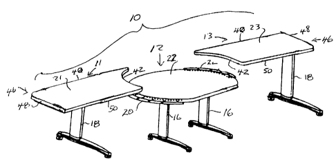
[0031] Reference is made first to Figures 1 and 2 showing a desk assembly 10
in
accordance with the first preferred embodiment of this invention. The desk
assembly 10
includes a center desk 12 and two wing desks, left wing desk 11 and right wing
desk 13.
[0032] The center desk 12 has a center desktop 22 which is supported on a
suitable
leg assembly comprising two L-shaped legs 16 secured to the underside of the
center
desktop 14 as best seen in Figure 2. Also secured to the under surface of the
center
desktop are two support brackets 20 and 24 which provide a support ledge
extending
laterally from the center desktop 14 on each side thereof which brackets are
adapted to
receive and support thereon a concave end edge 42 of each of the left and
right wing
desks. As seen in Figure 1, the distal ends ofthe wing desks 11 and 13 are
supported
spaced from the center desk on respective L-shaped legs 18.
[0033] Figure 2 shows the desk assembly 10 of Figure 1 from a bottom view in
an
assembled condition oriented in a 90° position. Figure 3 shows the desk
of Figure 2 in
top view.
[0034] The peripheral shape of the center desktop 72 is a segment of a circle
about
center point 30 as bounded by a convex edge 32 and a cord edge 34. The convex
edge 32
comprises an arc of a constant radius from the center 30. The convex edge 32
extends
from a first end point 36 to a second end point 38. The cord edge 34 comprises
a cord of
the circle and extends from the first end point 36 to the second end point 38
preferably as
a substantially straight line.
[0035] The right-hand wing desk 13 has a right-hand wing desktop 23 and the
left-
hand wing desk has a left-hand wing desktop 21. The peripheral shape of each
wing
desktop includes a straight rear edge 40 adjacent a concave end edge 42. The
concave
end edge 42 is formed as a concave arc of a constant radius equal to the
radius which
forms the segment of the circle comprising convex edge 32. Each concave end
edge 42 is
adapted to mate with the convex edge 32 of the center desktop 22 such that
with the
concave end edge 42 of the right-hand wing desktop 23 on the convex edge of
the right-
hand side of the cord edge 34 and the concave end edge 42 of the left-hand
wing desktop
4
CA 02436477 2003-07-31
21 on the convex edge 32 of the left-hand side of the cord edge 34, the right
and left-hand
wing desktops are attachable to the center desktop 22 in a plL~rality of
different angular
positions relative to the center point 30 and, therefore, relative to each
other. Different
angular orientations illustrated include: as shown in Figure 3, a right-angled
position in
which the rear edge 40 of the right-hand wing desk 13 and the rear edge 40 of
the left-
hand wing desk are normal to each other as seen in Figures 2 and 3; and, a
straight
position in which the rear edge 40 of the right-hand wing desk 13 and the rear
edge 40 of
the left-hand wing desk 11 lie in a straight line as seen in Figure 5.
[0036] The different angular positions which the wing desks may assume
relative to
the center desktop include intermediate angled positions between the right
angled
position of Figure 3 and the straight position of Figure 5. The intermediate
angled
positions include a 120° position as shown in Figure 4 in which the
rear edge 40 of the
right-hand wing desk 13 and the rear edge 40 of the left-hand wing desk 11 axe
disposed
to form an angle of 180° between them.
[0037] The center desktop 22 has a center desktop surface and each of the left
and
right wing desktops have their own wing desktop surface. The two wing desktops
21 and
23 are connectable to the center desktop 22 such that the wing desktop
surfaces form a
continuing surface with the center desktop surface.
[0038] As is apparent particularly from Figures 3 to 5, in. the preferred
embodiment,
the left-hand wing desktop 21 and the right-hand wing desktop 23 are mirror
images of
each other.
[0039] Each wing desktop has the straight rear edge 40 and a concave end edge
42.
The peripheral shape of each wing desktop is elongate extending away from the
concave
end edge 42 to a distal end 46 having a distal end edge 48 opposite to the
concave end
edge 42. The peripheral shape of each wing desktop includes a front edge 50
opposite to
the rear edge 40. Each of the concave end edge 42 and the distal end edge 48
span
between the rear edge 40 and the front edge 50. In the preferred embodiment
shown, the
front edge 50 is straight and parallel to the rear edge 40 and the distal end
edge 52 is
normal to the rear edge 40.
CA 02436477 2003-07-31
[0040] In the preferred embodiment shown, the convex edge 32 of the center
desktop
22 extends through an included angle A. In the preferred embodiment, the
included angle
is about 290°, the radius from the center 30 to the convex edge 32 is
indicated as R. The
width W of each wing desktop from the rear edge 40 to the front edge 50 is
about 90% R.
The length of the cord edge 34 from first end point 36 to second end point 38
is
approximately equal to the width W of the wing desktops.
[0041] Reference is made to Figure 6 which shows a second embodiment of a desk
assembly which is substantially identical to the desk assembly 10 shown in
Figure 1 and
differs merely in the fact that each of the two wing tables 1 I and I 3 have a
suitable leg
assembly such that they are independently supported as seen on two L-shaped
Iegs 18 and
may be freely movable upon a floor to assume desired angular orientations
about the
center desktop 12. In Figure 6, the wing desks are shown in an exploded view
spaced
from the center desk, however, it is to be appreciated that in vse, the desks
are to be
arranged as to assume positions in angular orientations as shown, for example,
in Figures
3 to 5.
[0042] Reference is now made to Figures 7, 8 and 9 which illustrate the desk
assembly 10 illustrated in Figures 1 to 6 as used in combination with a
plurality of
vertically disposed walls formed from planar screen panels 70. Such planar
screen panels
70 are well known as, for example, disclosed in various U.S. patents such as
U.S. Patent
6,286,275 to Edwards, issued September 11, 2001 and in U.S. Patent 5,784,843
to Greer
et al, issued July 28, 1998 and U.S. Patent 6,134,844 to Cornell et al, issued
October 24,
2000.
[0043] Reference is again made to Figures 7, 8 and 9 which illustrate a
pluarality of
vertically disposed planar screen panels 70 forming walls to define workspaces
with a
desk assembly 10 in accordance with the present invention provided in various
of the
corners provided between different screen panels 70.
[0044] Referring to Figure 7, the various panels 70 are disposed at 90°
to each other.
That is, as between a first panel 70a and a second panel 70b, an included
angle is
provided of 90°. A desk assembly in accordance with the present
invention is located in
6
CA 02436477 2003-07-31
the included angle between the first and second panels with the right-hand
panel 70c
located adjacent the rear edge of the right-hand wing desk 13 extending
parallel thereto
and the left-hand panel 70b located adjacent the rear edge of the left-hand
wing desk
extending parallel thereto.
[0045] Reference is made to Figure 8 which shows a plurality of panels 70 each
disposed so as to form an included angle between each of 120°. Three
desk assemblies
in accordance with the present invention are shown being provided in the
corners
between each two adjacent panels in each case with the straight rear edges of
the left and
right wing desks being disposed adjacent and parallel to their respective
panels.
[0046] Figure 9 illustrates a condition in which the panels 70 are disposed in
a zigzag
manner with each adjacent panel 70 forming an included angle of about
120° with its
adjacent panel. A desk assembly 10 in accordance with the present invention is
provided
in the corners formed between adjacent panels which corners form an included
angle of
about 120°.
[0047) While each of Figures 7, 8 and 9 illustrate configurations for the
panels which
adopt the same included angle throughout in each configuration, this is not
necessary and
each of the panel structures shown in Figures 7, 8 and 9 could be joined to
the other. It is
also not necessary that merely included angles of 90°, 120° or
180° be utilized. In
accordance with the present invention, the desk assembly is able to
accommodate any
included angles between panels of between 90° and 180°. This is
advantageous when
customizing the relative location of the panels in the desk assemblies and is
to be
appreciated that the desk assembly in accordance with the present invention is
particularly adapted for use with free-standing movable planar screen panels
which can
be coupled at their ends to each other in a manner that the panels can assume
any angle
between 90° and 180°. Of course, insofar as the walls are to be
built permanently, then
the walls may be built permanently to have any included angle formed
therebetween.
[0048] Reference is made to Figure 10 which illustrates a workplace wall
system
substantially the same as that disclosed in IJ.S. Patent 6,286,275 to ~dwaxds,
issued
September 1 l, 2001, however, modified so as to show a desk assembly 10 in
accordance
7
CA 02436477 2003-07-31
with a third embodiment of the present invention. As seen in Figure 10, a
workspace
management system 68 is disclosed which comprises a first straight wall 72 and
a second
straight wall 74. Wall 74 is fixedly connected at its end to 'vall 72. The
walls may be
constructed in many known manners. The walls could be of a permanent
construction.
Preferably, the walls are constructed from prefabricated modular wall
partitions such as
those taught in any of U.S. Patent Nos. 4,535,577; 4,685,255; 5,209,035;
5,277,005;
5,394,658 and 5,638,650. The walls are formed from individual partitions
indicated as
72a, 72b, 72c, 72d and 74a, 74b, with each partition representing a rigid
rectangular
frame comprising vertical frame members and horizontal frame members to which
covers
are secured, preferably, for easy removal to access vertical and horizontal
raceways
underneath the covers in the interior of each partition.
[0049] The individual partitions may have different heights as illustrated. ~f
course,
the walls could be a permanent construction in which case tl'~ey could have a
height
which extends fully to the ceiling. For ease of illustration, merely one
workstation is
shown in Figure 10 in which a desk assembly 10 in accordance with the present
invention
is oriented in a right-angled confgguration with the center desk 12 disposed
in the corner
formed by partitions 74b and 72b with the wing tables extending therefrom. As
seen, the
straight rear edge 40 of the left wing desktop 11 is disposed to extend along
and parallel
to the wall 74. The straight rear edge 40 of the right wing desktop 13 is
disposed
adjacent and parallel to the wall 72.
[0050] Figure 10 illustrates the distal end of the wing desktops 11 and 13
being
supported on the partition via brackets indicated as 78 secured to the
partitions. Thus, in
a known manner, each of the wing desk 11 and l 3 may be supported from the
walls 72
and 74. Similarly, while not shown, the center desktop 12 may be supported
from the
walls, however, it is generally preferred that the center desktop be
independently
supported on a suitable leg assembly.
[0051] The walls 72 and 74 bordering on the desk assembly are shown as
extending
to a height above the height of the desk surfaces as is prefer.°ed.
8
CA 02436477 2003-07-31
[0052] Walls to be used in accordance with the desk assembly 10 of the present
invention may comprise vertically disposed planar screen panels such as those
illustrated
in Figure 10 and preferably in which the planar screen panels are connected at
their ends
as to other panels permitting the panels to assume relative to each other
virtually any
angular configuration although preferred angles are angles between 90°
and 180°.
Various connecting assemblies are well known to connect the ends of different
panels
such that the panels may be adjusted to have an included angle between the
panels of
being any angle between 90° and 180°.
[0053] The preferred center desktop 22 has been described as having a cord
edge 34
which extends over an included angle of about 70° thus with the convex
edge 32
extending through an included of angle of about 290°. It is preferred
that the convex
edge 34 extend through an included angle of at least 210°. l:n the
preferred embodiments,
when assembled, the straight rear edge 40 of each wing desk is disposed to
extend
substantially tangential to the convex edge 32 of the center desk 12.
Therefore, in order
to accommodate, for example, a 90° orientation as illustrated in Figure
2, the width W of
a wing desktop will, to Borne measure, determine the length of the cord edge
34 if in the
90° configuration as illustrated in Figure 2, the front edge 50 of each
wing desk is not to
extend forwardly beyond the cord edge 34. Preferably, the cord edge 34 has a
length of
at least 20 inches which is the width of a typical computer keyboard.
[0054] The included angle ~ of the convex edge 32 will be a function of the
width W
of the wing tables and the radius R of the center tables.
[0055] The preferred embodiment shows the cord edge :34 as comprising a
straight
line. It is to be appreciated that this is not necessary and what is referred
to as the cord
edge 34 need not be straight but may be slightly concave or slightly convex as
illustrated,
for example, in dotted lines 82 and 84 in Figure 2 showing a convex
orientation 92, a
concave orientation 94 and, as well, a convex orientation 96 preferably with
the radius of
these edges 94 and 96 being of a radius which is substantially greater than
the radius R of
the circle desktop.
9
CA 02436477 2003-07-31
[0056) It is preferred that each of the wing tables have the same width W,
however, it
is to be appreciated that it is not necessary. It is preferred that the rear
edge 40 be
straight. The front edge 50 and the distal end edge 48 need not be straight.
Alternate
configurations for these edges are shown in dotted lines as 96, 97 and 98 in
Figure 2. ~f
course, each of the wing tables may have a different length L.
[0057) While the invention has been described with reference to preferred
embodiments, the invention is not so limited. For a definition of the
invention, reference
is made to the appended claims.