Note: Descriptions are shown in the official language in which they were submitted.
CA 02436634 2003-08-05
Title
PASTE DISPENSER
Scope of the Invention
[0001] This invention relates to material dispensers and, more particularly,
to a
dispenser for dispensing paste-like material from a tubular container by
twisting of the
tubular container.
Background of the Invention
[0002] Various dispensers such as cocking guns are adapted for dispensing
paste in
which a piston displaces the paste from a cylindrical tube. Soap dispensers
are known in
which soap and other fluids may be dispensed from containers as by the
activation of a
manually operated or automated pump.
[0003] Prior art devices such as piston driven cocking gun type mechanisms and
liquid pumps are not conveniently adaptable for controlled, manual or
automated
dispensing of pastes.
Summary of the Invention
[0004] To at least partially overcome these disadvantages of previously known
devices, the present invention provides a simplified arrangement for
dispensing material
from a deformable container by collapsing the container through twisting.
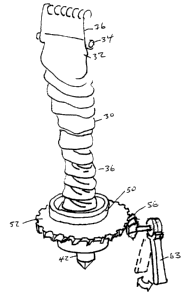
[0005] An object of the present invention is to provide a simplified dispenser
for
materials and, more particularly, for pastes or viscous fluids.
[0006] Another object of the present invention is to provide an apparatus
adapted to
collapse a tube by twisting the same.
[0007] In one aspect, the present invention provides a method of and apparatus
for
dispensing paste from a collapsible container elongate about an axis from a
first closed
end to a second open end, the method comprising rotating one of the first end
and second
end relative to the other to twist the container about the axis, thereby
collapsing the
CA 02436634 2003-08-05
container, compressing paste contained therein and extruding the paste from
the second
open end.
[0008] In another aspect, the present invention provides a dispenser for
material
comprising:
[0009] a collapsible container elongate about an axis from a first end to a
second end,
[0010] the container closed but for an outlet open at one of the first end and
the
second end,
[0011] a housing to receive the container with the first end of the container
secured to
the housing substantially against rotation about the axis relative to the
housing,
[0012] the second end of the container secured in the housing journalled for
rotation
about the axis in a first direction and against rotation in an opposite
direction to the first
direction,
[0013] an activation mechanism for rotating the second end of the container in
the
one direction, whereby rotating the second end of the container about the axis
twists the
container about the axis compressing material therein and extruding the
material from the
outlet.
Brief Description of the Drawings
[0014] Figure 1 is a schematic exploded view of a dispenser in accordance with
the
first embodiment of the present invention;
[0015] Figure 2 is a schematic cross-sectional front view of the dispenser of
Figure 1;
[0016] Figure 3 is a cross-sectional view along section line 3-3' in Figure 2;
[0017] Figure 4 is a schematic pictorial view of selected components of the
dispenser
of Figure 1 with the tube in a filled condition;
[0018) Figure 5 is a view similar to that of Figure 4, however, after the tube
has been
twisted for dispensing fluids;
[0019] Figure 6 is a schematic view similar to that of Figure 4, however,
showing the
use of a motor rather than a lever;
2
CA 02436634 2003-08-05
[0020] Figure 7 is a schematic view similar to that of Figure 6, however,
showing a
single motor as adapted to simultaneously dispense from two tubes;
[0021] Figure 8 is a view similar to that of Figure 7 for dispensing from two
tubes but
with two levers for manual dispensing;
[0022] Figure 9 is a view similar to Figure 8, however, showing the use of
three
levers;
[0023] Figure 10 is a cross-sectional view of another embodiment of a tube for
use in
the present invention which tube is adapted to carry two products;
[0024] Figure 11 is a cross-sectional view along section line 11-11' of Figure
10;
[0025] Figure 12 is a view similar to Figure 6 but of another embodiment of
the
invention.
Detailed Description of the Drawings
[0026] Further aspects and advantageous of the present invention will become
apparent from the following description taken together with the accompanying
drawings
in which:
[0027] Reference is made first to Figures 1 to 5 which show a first embodiment
in
accordance with the present invention and in which a dispenser 10 is shown
comprising a
housing 12 within which a paste filled container 18 is to be received. The
housing 12 is
shown as having a rear wall 20, two side walls 22 and 24 and a floor 26. A
cylindrical
opening 28 extends downwardly through the floor. The container 18 comprises a
cylindrical tube 30 held closed at a first upper end 32 by a closure pin 34
and having an
open, second lower end 36 received in a cap 38.
[0028] The second end 36 of the tube 30 presents an outlet from the tube 30
which is
sealably secured to the cap 36 in communication with an inlet opening to the
cap 38 to an
internal passageway 40 through the cap to an outlet nozzle 42 from which
material is to
be dispensed. Preferably, as best seen in Figures 2 and 3, a one-way valve is
provided in
the nozzle 42 comprising a plurality of resilient flexible vanes 46 which are
biased to
3
CA 02436634 2003-08-05
assume a closed position as shown in Figure 3 yet will deflect away from their
mutual
edges to permit material to be dispensed outwardly.
[0029] As best seen in Figure 2, the tube 30 extends from the first end 32 to
the
second end 36 about an axis 48. The tube 30 is a cylindrical tube coaxially
about the axis
48. The cap 38 externally carries an upper bearing flange SO and a lower
bearing flange
S I each of which have surfaces which are disposed coaxially about the axis
48. The cap
38 also carnes a radially outwardly extending activation flange S2 which
carries gear
teeth S3 on its perimeter.
[0030] The side wall 24 has a bore S4 and two locating holes S3 and SS in
which there
is mounted a activation mechanism comprising a bevel gear S6 mounted on an
axle S8 to
be journalled within the bore S4. A ratchet mechanism S8 is provided which has
a fixed
disc 60 fixably coupled to the housing side wall 24 by pins S9 and 61 being
received in
holes S3 and SS. The axle S6 extends through the fixed disc 60 and is fixedly
coupled to
a one-way rotatable clutch disc 62. The clutch disc 62 may rotate with the
gear S6 only
in one direction relative the fixed disc 60. A ratchet lever 63 and its disc
64 is journalled
to the clutch disc 62 for rotation about the same axis as the axle S8. The
ratchet lever 63
on rotation of the lever 63 in one direction causes rotation of the gear S6
the same
direction. On rotation of the lever 63 in the other direction, the lever 63
rotates, however,
the clutch disc 62 does not rotate. Rotation of the lever 63 in a first
direction will rotate
the clutch disc and thereby the axle and the gear 56 in the one direction. On
rotation of
the lever in the other direction, the lever and its disk 64 will move in that
direction,
however, the clutch disc 62, axle and gear S6 will not rotate in the other
direction and
their position will remain unchanged.
(0031] In an assembled condition as shown in Figure 2, via movement of the
lever 63
in one direction, the gear 56 will engage the activation flange S2 and thus
rotate the cap
38 and, hence, the second end 36 of the tube 30 relative to the first end 32.
(0032] Assembly of the dispenser of Figure 1 is accomplished by locating the
container 18 within the housing 12 and moving it vertically downwardly so as
to locate
the lower bearing flange S 1 within the opening 28 in the floor 26.
Subsequently, a slide
4
CA 02436634 2003-08-05
plate 65 is slid horizontally into two slots 66 and 68 in the side walls 22
and 24. The
slide plate 65 has a U-shaped interior bearing surface 70 which closely
engages the upper
bearing flange 50. As seen in Figure 2, the cap 38 is secured to the housing
12 journalled
for rotation about the axis 48 by reason of the lower bearing flange 51 being
journalled
within the opening 28 of the floor 26 and the upper bearing flange being
journalled
within the bearing surfaces 70 of the slide plate 65. As well, the cap 38 is
located against
movement axially relative to the housing 12 as with the activation flange 52
extending
below the slide plate 64 and a shoulder 71 engaging the floor 26.
[0033] It will be appreciated that in vertically sliding the container 18 down
into the
opening 28 of the housing base 14, that the gear teeth 53 on the activation
flange 52 come
into engagement with the gear 56.
[0034] At an upper end of the housing, the side walls 22 and 24 have holes 72
and 73
there through within which a support rod 74 extends. A metal retaining spring
76 has a
helical coil 78 to extend about the support rod 74 and two hook arms 80 and 82
which
extend away from the coil at each end thereof. The hook arms 80 and 82 engage
about
the distal ends 84 and 86 of the closure pin 34 which is fixably secured to
and closes, as
by clamping, the upper end 32 of the tube 30.
[0035] The metal retaining spring 76 thus engages the first end of the
container 18 and
substantially prevents the same from rotating about the axis 48. Since the
coil 78 is
journalled on the support rod 74, the relative height of the closure pin 34 is
permitted to
change depending upon the angular orientation of the hook arms relative to the
support
rod 74. This permits variance of the relative height of the closure pin 34 and
thus the first
end 32 of the container 18 relative to the second end 36.
(0036] With rotation of the cap 38, the second end 36 of the tube 30 is
rotated relative
to the first end 32. With rotation of the tube 30 about the axis 48, the tube
becomes
twisted and contracts thus applying pressure to the material within the tube
such that
material under pressure becomes extruded from the nozzle 42 out of a one-way
valve.
Figure 5 illustrates a condition in which the cap 38 been rotated and thus the
tube 30 has
become twisted and is compressed.
CA 02436634 2003-08-05
[0037] The tube 30 preferably comprises a relatively flexible tube of plastic
film,
however, may comprise any material which permits twisting to pressurize the
material
therein without rupturing. For certain materials, cloth or fabrics or
composite flexible
sheet like films may be used.
[0038] In the preferred embodiment, the second end 36 of the tube 30 is shown
as
secured to the interior surface of the cap 38 as by gluing or welding. The
closure pin is
shown as a tube-like member with an axially extending slot to receive the
first end of the
tube 30 therein and to be crimped upon the tube to close the same. The closure
pin 34
may be secured onto the tube 30 via adhesion or welding or by a mechanical
clasp. In the
preferred embodiment illustrated in Figure I, the container 18 comprises an
integral
element which is intended for replacement and disposal whenever the material
from the
container may be fully dispensed. Preferably, therefore, the entirety of the
tube 30, the
closure pin 34 and the cap 38 may comprise recyclable plastic materials.
[0039] In accordance with other embodiments of the present invention, rather
than the
closure pin 34 comprising a disposable plastic portion the container 18, the
closure pin
may comprise for example an elongate cylindrical metal rod with a slot through
one side
of the tube which may be slid from one side over a flat closed end seam of the
closure
tube to retain the same against rotation. Similarly, the second end 36 of the
tube 30 may
be removably secured to the cap 38. For example, the second end 30 of the tube
may be
welding or bonded to a threaded end adapted to be threadably received into an
inlet of the
cap 38. Thus, such an arrangement, assembly and disassembly could require
threading a
new tube 30 into the inlet end of the cap 38 and applying a reusable metal
closure pin 34.
The new tube 30 could be entirely recyclable material such as plastic or
cloth. Many
modifications and variations will occur to persons skilled in the art.
[0040] Reference is made to Figure 6 which schematically illustrates a
container 18
the same as that shown in Figure 1 to 5, however, having slightly modified
gear teeth 56
on the actuation flange 52. In Figure 6, a motor 88 is illustrated having a
drive axle 58 to
which a drive gear 56 is coupled. Activation of the motor 88 rotates the gear
56 to rotate
the actuation flange 52 and hence rotate the container to dispense fluid. The
motor may
6
CA 02436634 2003-08-05
preferably be an electric motor which may be activated in known manners as by
a user
pressing a dispense button or by a touchless activation mechanism which would,
for
example, sense the presence of an object under the nozzle 42. The motor may be
driven
by electricity from an AC circuit or from batteries. A controller may
preferably be
provided for the motor. The controller would rotate the container a suitable
amount to
dispense an individual dosage or allotment of material. Depending upon the
nature of the
tube and the characteristics of pressure created in the tube upon rotation of
the tube, the
amount of material which is dispensed with rotation may vary depending upon
the extent
to which the tube has been twisted from a full position to a substantially
twisted empty
position. A control mechanism could be arranged to keep track of when a new
tube is
added and the extent to which the tube has been rotated so as to vary the
relative rotation
with each successive usage so as to provide for equal dispensed dosages at any
time
during empting of the tube. As well, the control mechanism may signal when the
tube is
fully twisted.
(0041] The motor preferably has a gear reduction mechanism to provide with a
compact and inexpensive low power motor with adequate power to rotate the
tube.
[0042] Reference is made to Figure 7 which schematically shows an arrangement
in
which a dispenser is to have two containers 18 and 118 mounted with the
actuation flange
52 of each to be engaged by a gear 56 driven by a single motor 88. One of the
containers
would be rotated in one direct and the other container would be rotated in the
other
direction for simultaneous dispensing of material from both containers via
their nozzles.
While not shown, both the nozzles could join into a single nozzle outlet or at
least
dispense at substantially the same location as, for example, to apply onto a
user's hand or
into the same receptacle.
[0043] Reference is made to Figure 8 which shows an arrangement in which two
containers 18 and 118 are arranged in the same dispenser for dispensing by
manually
activated levers similar to that shown in the embodiment of Figures 1 to 5.
Two ratchet
levers are schematically illustrated. A first lever 63 may independently be
operated so as
to dispense fluid from the container 18. The first lever has a tab 90 which
extends behind
7
CA 02436634 2003-08-05
a second lever 163. Activation of the second lever 163 will also necessarily
move the
first lever 63.
[0044] Reference is made to Figure 9 which shows an arrangement similar to
that in
Figure 8, however, in which there are three levers. A first lever 63 merely
activates
dispensing from the first container 18. A second lever 163 merely activates
dispensing
from the second container 118. A third intermediate 263 lever when activated
will move
both of the other levers and thus provide for simultaneous dispensing from
both
containers.
[0045] Reference is made to Figure 10 which illustrates a cross-sectional view
through a container 218 in accordance with another aspect of the present
invention. The
container 218 comprises two coaxial cylindrical tubes namely a first outer
tube 30 and a
second inner tube 230. The tubes are coaxial about an axis 48 and the inner
tube 230 is
coaxially received within the outer tube 30. Both tubes are closed at their
first ends 32 by
a closure pin 34. A cap 38 is engaged on the second end 36 of the tubes.
[0046] A first material is received within an inner compartment 96 formed
within the
inner tube 230. A second material is received within an annular outer
compartment 100
defined in the annular space between the inner tube 230 and the outer tube 30.
[0047] The cap 38 is formed with an inner passageway 40 in communication with
the
inner compartment 96 and with an annular outer passageway 140 in communication
with
an annular outer compartment 100. Each of the passageways 40 and 140 open to a
common nozzle 42 with a one-way valve. On relative rotation of the second end
of the
container 18, compressive forces are applied to the materials in both the
inner
compartment 96 and the outer compartment 98 and hence both materials will be
simultaneously dispensed. The quantity of each of the two components which
will be
dispensed will depend upon various factors including the relative viscosity of
each of the
two components and the resistance to flow through the two passageways 40 and
140.
Dispensing such that the quantity of one component dispensed bears a
relatively fixed
proportion to the quantity of the other component dispensed can be arranged
with
8
CA 02436634 2003-08-05
knowledge of their relative viscosities and by suitable selection of the
relative size of the
two passageways 40 and 140 and thus the resistance to flow there through.
[0048] Reference is made to Figure 12 which schematically shows an embodiment
similar to that in Figure 6, however, in which the container 18 has a
journalled gear 52
secured to a closed first end 32 of a tube 30 and dispensing is from an outlet
nozzle 42 at
a second end 36 of the tube. A motor 88 is provided to rotate the gear 52 and
the first end
32 relative the second end 36. The second end 36 may be held against rotation
but may
be permitted to slide axially.
[0049] Dispensers in accordance with the present invention are adapted to
dispense a
wide variety of flowable products including liquids, slurries and flowable
particulate
solid matters. Such products include highly viscous toothpaste, engine oil,
lubricating
oil, epoxy resins, lard, mustard, ketchup, honey, granular pumice soap, paint,
paint tints,
icing, cleansers, caulking compounds and roofing tar.
[0050] The tube illustrated in the preferred embodiment is cylindrical about
the axis
48. Other preferred configurations include a tube which is circular in any
cross-sectional
normal the axis, and a tube which is frusto-conical about the axis. The tube
may have
any shape which accommodates extrusion of material therefrom on twisting of
the tube.
Shapes which are not coaxial to the axis 48 may be used. The tube may be
formed as by
extrusion processes. Tubes which are multiple layer and formed by co-extrusion
may
have enhanced permeability and strength characteristics, yet are inexpensive.
To prevent
twisting from causing closure of the tube with substantial material trapped
upstream
therefrom, a mechanism like a helical coil spring may be provided to extend
axially
through the tube.
[0051] While the invention has been described with reference to preferred
embodiments, many modifications and variations will now occur to persons
skilled in the
art. For a definition of the invention reference is made to the appending
claims.
9